The Happy Node – 3D Printed Nodes for Recursive Aggregation
2021/22 Introduction to Digital Fabrication, Final – Neha Jayanth Pattanshetti, Alessandra Weiss, Luca Wenzel
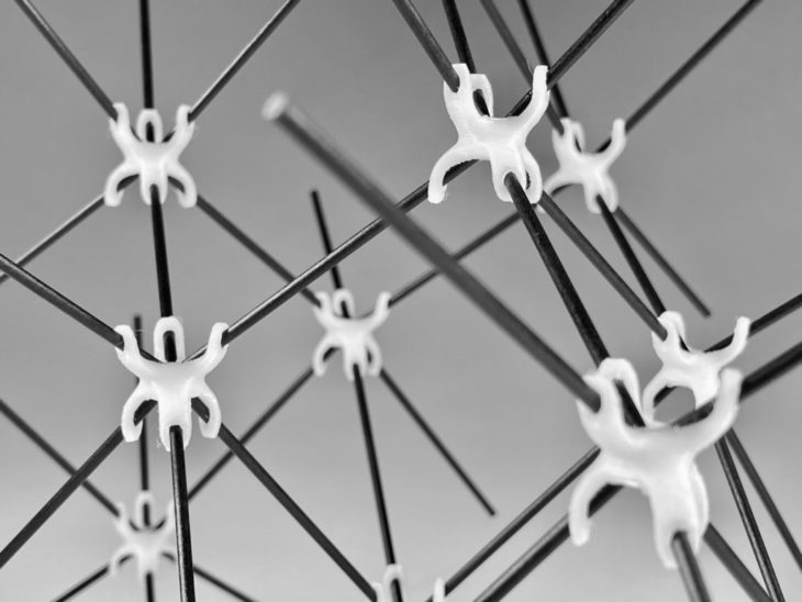
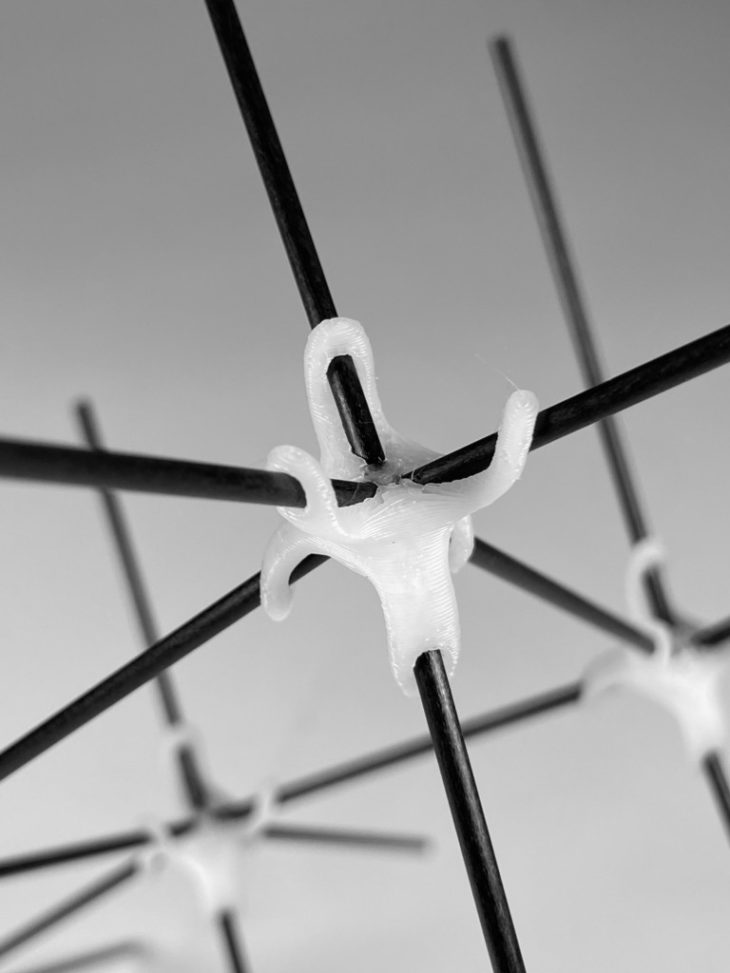
The Happy Node is a 3D printed node that forms a volumetric aggregation together with 2 mm fibreglass rods. It uses less material than conventional nodes, that encompass the entire rod at the joint, by hugging the rod only on one side. This also makes the node more flexible, which allows for a much easier assembly. It forms a pocket from the centre of the node along each arm and ends with a hole on each ending, to secure the rod positions. The project was preceded by a thorough testing process that led to the optimization of the node.
Final Model
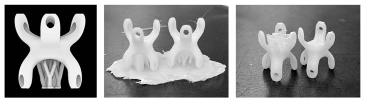
Investigation Process
The first iteration was an attempt to create a material saving node that didn’t surround the rods on all sides. Iteration two was printed alongside iteration one and was intended to investigate the stability of the node, without connecting the three arms with bridges. Both prints had an angle of 45 degrees, so that no supports were required to print them. The first iteration print failed and was soon discarded, as the second print proved that the support-heavy bridges weren’t necessary. Iteration two had three different sized holes and pockets, to test the optimal diameter for the fitting of the rods. It was tested to be at 2.2 mm.
In iteration three the arms were mirrored vertically and then rotated by 60 degrees, to allow for a three-dimensional aggregation. Though the rest of the geometry remained unchanged, the print failed, as the node was missing the large horizontal bottom surface from iteration two. Because of the rounded bottoms of the legs, the contact points to the raft were too small and the printer nozzle pushed one of the legs away in the printing process. In iteration four the problem was resolved, by chamfering the bottoms of the legs into a flat surface of approximately 3 mm in diameter. Additionally the arms were shortened to save material and decrease the printing time from 27 to 21 minutes per node.
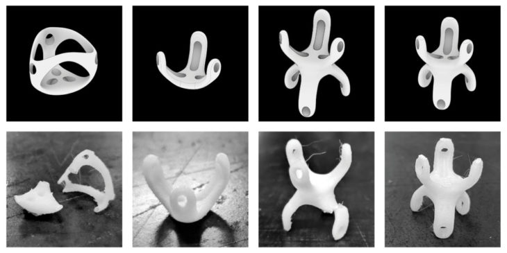
Iterations 1-4
Final Iteration
For the final iteration the angles on one side of the node were altered from 45 degrees to 35 degrees to create a wave pattern in the aggregated geometry. The arms were kept at the same length as in iteration four. The pockets were slightly deepened to create a better anchor for the rods. For the aggregation, the rod length was set to to 6,9 and 5,8 cm. The nodes are mirrored on every level so that the 35 degree arms always connect to 35 degree arms on the other end of the rod and vice versa for the 45 degree arms.
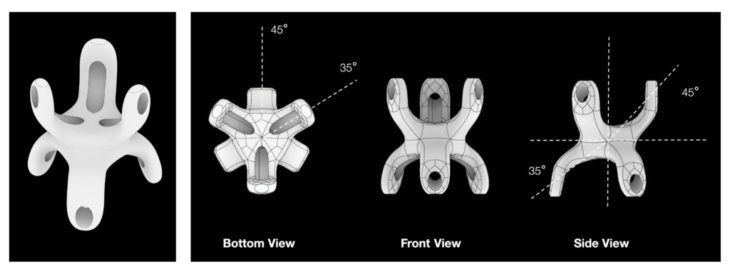
Final Node
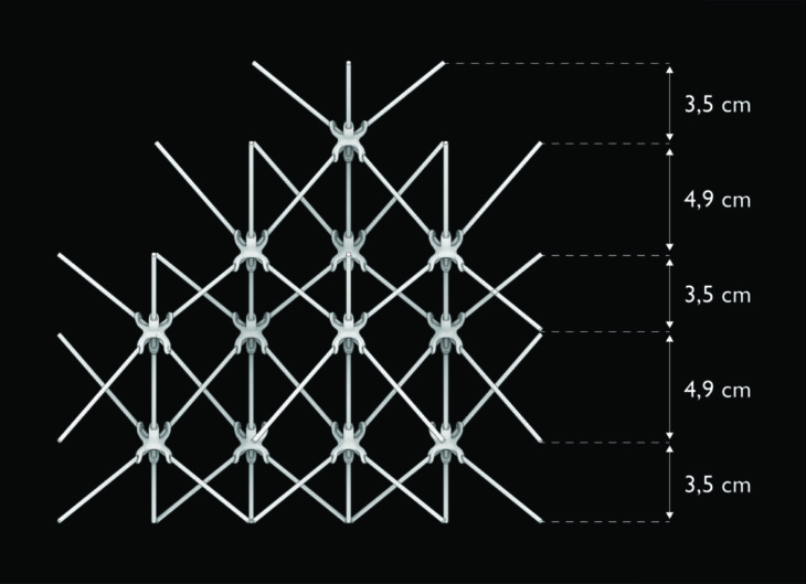
Front View Aggregation
Final Node
Meshmixer Optimization
In order to optimize the printing time and material usage, tree supports were generated using Autodesk Meshmixer. The program generates thin efficient support trees for overhangs. Although the printing time was similar in this case, the supports with Meshmixer used less material than the standard Z-Suite supports. The removal was much easier as there were less contact points. This also resulted in a considerably smoother surface.
| Z-Suite | Meshmixer | |
| Time | 21 min | 21 min |
| Material usage | 0.61m (1g) | 0.57m (1g) |
Left: Meshmixer Support Generation, Centre and Right: Printed Conventional Supports and Tree Supports
Printing Process
With a time limit of 4 hours it was necessary to print all final nodes together and in the closest array possible. The closer the nodes are next to each other on the printing bed, the less time the print will need, as a smaller raft will be needed. By doing so, it was possible to reduce the printing time from 21 minutes per node, to 18 minutes per node.
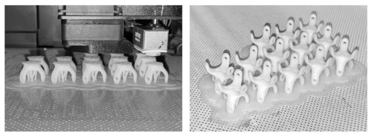
Printing of Final Nodes
Final Aggregation Module
The final module was created by connecting all 13 nodes with fibreglass rods. Black rods were used to be in contrast with the white nodes in order to highlight the joint details. The rods on the outside of the aggregation connect only to one node. This is to demonstrate that the aggregation could be continued infinitely, by adding more nodes and rods. The geometry was designed in a way that the module could be rotated in any direction and stand on any side.
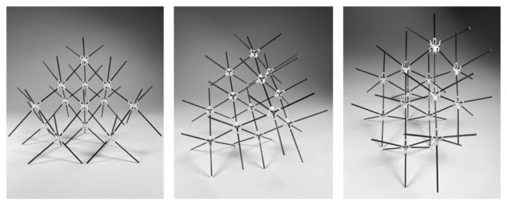
Final Aggregation
Technical Data:
- Material: Z-ABS Filament, 2 mm Fibreglass Rods
- Machine: Zortrax M200 Plus
| Testprints 1 & 2 | Testprint 3 | Testprint 4 | Final Print | |
| Total number of nodes: | 2 | 1 | 2 | 13 |
| Total print time: | 0h24min (12m / node) | 0h27min (27m / node) | 0h42min (21m / node) | 4h06min (18m / node) |
| Total filament quantity: | 0.78m (2g) | 0.70m (2g) | 1.07 (3g) | 5.63m (13g) |
| Material type: | Z-ABS | Z-ABS | Z-ABS | Z-ABS |
| Machine specifications: | Zortrax M200 Plus | Zortrax M200 Plus | Zortrax M200 Plus | Zortrax M200 Plus |
| Layer thickness: | 0.19mm | 0.19mm | 0.19mm | 0.19mm |
|
Support types, angles and specifications: |
Editable, lite, 20%, Gap xy> 0.36mm, Density 3.50mm |
Editable, lite, 12%, Gap xy> 0.36mm, Density 3.50mm |
Editable, lite, 12%, Gap xy> 0.36mm, Density 3.50mm; Tree supports generated using MeshMixer see –> |
Tree supports: Max angle 70, Density 23, Post diameter 1mm, Tip diameter 0.4, Base diameter 1.6mm |
| Infill type, percentage, & pattern: | Normal, 20%, Pattern 0 | Normal, 20%, Pattern 0 | Normal, 20%, Pattern 0 | Normal, 20%, Pattern 0 |
| Seam: | Random | Random | Random | Random |
|
Mesh errors & fixes: |
Moved forward with removal of excess material. |
End of legs chamfered for next iteration. |
Tree supports tested. |
Flawless. |
Credits
The Happy Node is a project of IAAC, the Institute for Advanced Architecture of Catalonia, developed during the Master in Advanced Architecture (MAA01) 2021/22 by students: Neha Jayanth Pattanshetti, Alessandra Weiss, Luca Wenzel; faculty: Lana Awad
