Optimizing geometry via design to enhance its effect on passive ventilation systems when 3D printing unfired clay
Lili Tayefi
Abstract
To attain embedded performance capacity in the architectural element of the wall while maximizing material efficiency, time, and exploiting the potential of thermal capacity in passive performative design in context to large scale 3d printing on site with local materials. The role of openings in the optimization of thermal performance is imperative, and has not yet been thoroughly investigated. Thus the research seeks to understand the types of openings in relation to the 3D printing contour and the performative result they provide.
In common clay or ceramic 3D printers to create openings through a geometry, the piston is turned off in order to discontinue deposition, while the nozzle travels to its next point where it then begins to deposit material once more. When printing with single continuous contour crafting of large scale architecture on site it is imperative to optimize time, and minimize delay. Thus not stopping the robotic movement nor the piston pressure while printing to create geometries such as openings.
When the on and off commands of the piston in relation the robotic movement are calibrated to sync timing, the method is still, as of now, timely and inefficient for large scale, onsite manufacturing due to the current limits in technology. The on and off command makes it difficult to print while allowing for accurate openings in the printed surface due to its underdeveloped nature. How can one maximize passive cross ventilation at an architectural scale without integrating external components such as pipes or vents in the construction of the building envelope, given the context of onsite printing, and the limitations of single contour crafting?
Approach
This paper introduces three methods of how the design of a single continuous contour in 3d printing can allow for openings within the geometry of the wall. An opening is defined as “a space or gap” by Oxford Dictionary [1]. Three types of openings are defined here, through the a section of a wall geometry at 1:1 scale. Each opening type has a varying performative intention in cross sectional airflow by ventilating from the exterior to interior of the building or from either side into the wall thickness. The results of each case study are simulated using Rhino CFD and Autodesk Flow to understand a relationship between geometry, wind speed and wind pressure.
- A ‘pipe’ opening: opening allowing direct cross section airflow from exterior to interior. With the theoretical background of venturi effect [2], the relation between speed and pressure should differ the phenomena output of air temperature impact. When printing a pipe through the wall, if the entrance geometry is raised above the exit geometry, the model should capture air from high pressure and release to low pressure, based on the science of the ancient windcatchers of Iran [3]. Furthermore, according to the Venturi Effect [2] if the air entrance geometry is double the size of the exit geometry, a funneling effect will allow an increase of air pressure is created and thus an increase of airspeed, resulting to cooler interior air. Difference entrance and exit dimension ratios are tested. Pipe printing rules: When printing continuous contour for pipe technique, the geometry must have support walls underneath the pipe inside wall geometry. This can be achieved by doubling the line of the wall beneath. Second, when looking directly at wall in elevation, when one half of the opening is covered visually by interior pipe, the other side will begin to be visible, resulting in minimum 45 degree pipe angles [4].
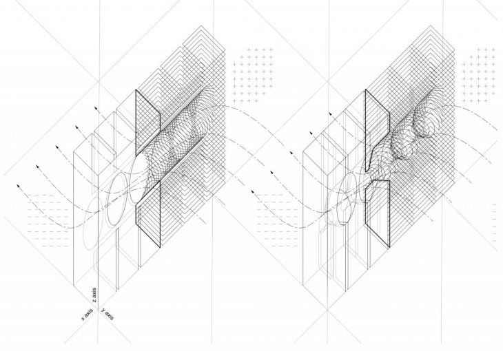
IMAGE 1
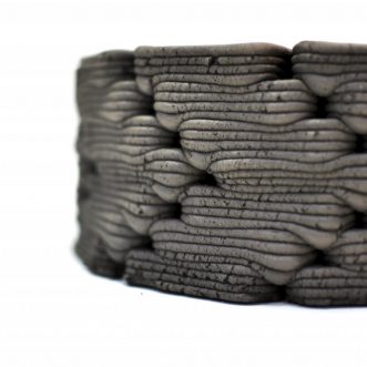
Case Study: straight wall, five pipe openings, 40x30x5cm,
The drawing shows contour printing of two types of pipe openings, one with angled pipes, the second with a funneling effect. - A ‘channel’ opening: An airflow system allowing access through and within the wall itself. Considering the Bernoulli effect [5], entrapment of air happens by an entrance, exit and continuous pipes throughout wall geometry to maximize airflow path in order to enhance air speed and thus lower resulting temperature [2]. If working solely with venturi effect, considering an external pull of the wind this phenomena may work however when if passive, the stack effect should take place [6]. Meaning the elongated pipe geometry should always be inclined upward to direct airflow as if a trombe wall [7]. A technique with continuous upward spiraling of air channels is yet unresolved considering the 3d print parameters of a single contour.
Interior channeling printing rules: Firstly using the double line method within the wall, one can begin to cantilever each opening oval amongst the interior double walls. Second, in the exhibited prototype an optimized on and off code has been used to create a relationship between the outside and the inside of the wall, this can again be avoided using double walls.
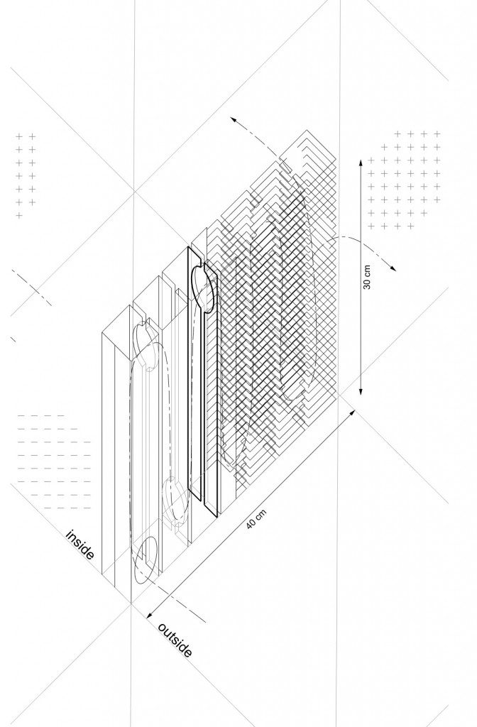
IMAGE 2
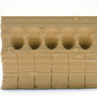
Case Study: straight wall, five channel columns, 40x30x3cm,
The drawing shows contour printing of channeling.
- Microperforations: can be created through a deviating path of the single contour by strategically placing them on the outer surface of the wall, lowest and highest region one can create a trombe wall using the stack effect. The advantage of microperforations is they can be used in any area, at any density, and at different scales, thus being multi purposeful in its ventilation use. There is a direct relation between the number of openings, relative size, and location (testing high/low pressure).
Microperforation printing rules:- Microperforations can be made by deviating the toolpath. If the maximum cantilever in elevation from one layer to the next is 30 percent of the previous layer thickness, deviating a line means to print 150% off of the layer beneath, with no necessary structure under the material, thus allowing it to ‘droop’. This method deviates the line by maximum exaggeration until the threshold of material breakage, once this is done for a few layers (in relation to layer height and deposition thickness) the top layer will continue the original toolpath, thus ‘bridging’ the gap left behind. The bridge allows for a small opening of air into the wall.
- A similar method is to deviate the line in the format of a cup, by following the 30-45% cantilever out and upward, however returning the final layer contour to be straight once more. [image 3]
- Texturing techniques can be used, by creating a pattern for several layers and offsetting the same pattern in the same number of layers above. When this pattern is repeated the offsets in between will be perforated. This pattern can be created by using a sine or cosine curve, or printing different geometries on top of one another, ie alternating between squares and triangles [image 4].
- Printing lines in space, several millimeters above the surface of the top contour can allow for deviated paths.There is a direct relation between the height of print contour, the deviated path distance when hitting the surface, all which can be defined by the sine or cosine amplitude and frequency of the toolpath in elevation. The disadvantage of this method is that it is less predictable.
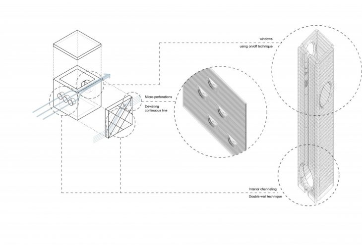
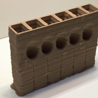
IMAGE 3
Microperforations and channeling on facades.
Results
CFD results of the first two case studies prove that there is an insignificant change between the first two case studies at the scale of this operation. In theory the design difference between the first and second study would differ at the scale of ancient Iranian wind towers. This is due to the fact that wind towers work with uninterrupted airflow at a minimum altitude of 6 meters above a building.
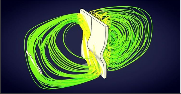
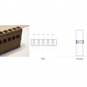
IMAGE 4
Rhino CFD simulation of basic wall element with ‘sliced’ opening
in collaboration with Angelos Chronis
Conclusion
In the proposed layer deposition protocol, the optimized printing technique developed avoids turning off air pressure. Instead, various methods of printing with one continuous toolpath are developed in order to increase the speed of printing and therefore increase productivity, while enhancing the architectural performance of the wall itself in relation to number of openings, sizes and locations along the architectural element. Further iterative testing of the above theories is necessary, at a larger scale, physically and in simulation, in order to understand the significance of airflow curation when designing a building with additive manufacturing technology. The benefits of 3D printing architecture are numerous: from optimizing and automating construction techniques, to minimizing the carbon footprint and transportation systems from industry to construction site, and allowing for the opportunity to print with natural materials such as the ancient and well respected earth clay. When 3D printing architecture, it is imperative to be time efficient with the robot and extrusion system, thus it is beneficial to design and print with continuous single contour crafting. Therefore it is valuable to further develop the proposed opening techniques for optimization and performance in architectural applications.

References:
- Strauß, Holger, and Ulrich Knaack. “Additive Manufacturing for Future Facades: The potential of 3D printed parts for the building envelope.” Journal of Facade Design and Engineering. IOS Press, 01 Jan. 2015. Web. 21 Apr. 2017. <
http://content.iospress.com/articles/journal-of-facade-design-and-engineering/fde0042
>. - Strauss, Holger, and Ulrich Knaack. “Additive Manufacturing for Future Facades.” Journal of Facade Design and Engineering. N.p., n.d. Web. 21 Apr. 2017. <
http://journals.library.tudelft.nl/index.php/jfde/article/view/875
>. - Gardan, J., F. Danesi, L. Danesi, and A. Schneider. 3D Printing device adaptable to Computer Numerical Control (CNC). Proc. of 19th European Forum on Rapid Prototyping and Manufacturing, 2014, Paris, France. 1-6. N.p.: Alexandre Schneider. Web. 21. Sep. 2015.
<https://www.researchgate.net/publication/263361941_3D_Printing_device_adaptable_to_Computer_Numerical_Control_CNC
>. - Herpt, Olivier Van. “Functional 3D Printed Ceramics.” Olivier Van Herpt. N.p., n.d. Web. 21 Apr. 2017. <
http://oliviervanherpt.com/functional-3d-printed-ceramics/>.
- Bennett, Jessica. Wind Design Guide. Vol. BBSC 433. N.p.: n.p., 2007. Architectural Aerodynamics. Victoria University of Wellington. School of Architecture. Web. 21 Apr. 2017. <
http://www.victoria.ac.nz/architecture/centres/cbpr/publications/architectural-aerodynamics/pdfs/BBSC_433_Jessica-Bennett_Wind-Design-Guide.pdf
>. - Minke, Gernot. Building with earth: design and technology of a sustainable architecture. Basel, Switzerland: Birkha?user, 2013. Print.
- Ghayour Kazemi, Amir , and Amir Hossein Shirvani. “An Overview of Some Vernacular Techniques in Iranian Sustainable Architecture in Reference to Cisterns and Ice Houses.” Journal of Sustainable Development. 1st ed. Vol. 4. Tehran: ISSN 1913-9071 , 2011. 264-70. Journal of Sustainable Development. Canadian Center of Science and Education, Feb. 2011. Web. 21 Apr. 2017. <
http://citeseerx.ist.psu.edu/viewdoc/download?doi=10.1.1.665.8755&rep=rep1&type=pdf
>. - Amirkhani, Aryan, Hanie Okhovat, Mohammad Reza Pourjafar, and Ehsan Zamani. “HISTORICAL ICE-HOUSES: REMARKABLE EXAMPLE OF IRANIAN CULTURAL HERITAGE.” Acee (n.d.): 1-10. The Si lesian Universi ty of Technology. Web. 21 Apr. 2017. <
http://yadda.icm.edu.pl/yadda/element/bwmeta1.element.baztech-article-BSL6-0012-0015
>. - Su, Yuehong, Saffa B. Riffat, Yen-Liang Lin, and Naghman Khan. “Experimental and CFD study of ventilation flow rate of a Monodraught™ windcatcher.” Energy and Buildings 40.6 (2008): 1110-116. Science Direct. Web. 21 Apr. 2017. <
http://www.sciencedirect.com/science/article/pii/S037877880700237X
>. - Jazayeri, E., and A. Gorginpour. “Construction of windcatcher and necessity of enhancing the traditional windcatcher.” Magazine of civil engineering 24.6 (2011): 56-60. Web. 21 Apr. 2017. <
http://engstroy.spbstu.ru/eng/index_2011_06/jazayeri.html
>. - Mahdavinejad, Mohamadjavad, and Kavan Javanroodi. “Natural ventilation performance of ancient wind catchers, an experimental and analytical study – case studies: one-sided, two-sided and four-sided wind catchers.” International Journal of Energy Technology and Policy 2.1 (2012): 559-64. CiteSeerX. Web. 21 Apr. 2017. <
http://citeseerx.ist.psu.edu/viewdoc/citations;jsessionid=AE1A26E6FB429F3F1CC45D37B5AE81C3?doi=10.1.1.416.4368
>. - Ghadiri, M. Hossein, N. Lukman, N. Ibrahim, and Mohd Farid Mohamed. “Computational Analysis of Wind-Driven Natural Ventilation in a Two Sided Rectangular Wind Catcher.” International Journal of Ventilation 8.12 (2014): 1241-246. World Academy of Science, Engineering and Technology. Web. 21 Apr. 2017. <
http://www.academia.edu/10433509/Visualized_Flow_Patterns_around_and_inside_a_Two-Sided_Wind-Catcher_with_the_Presence_of_Upstream_Structures
>. - Ghaemmaghami, P.S., and M. Mahmoudi. Research Gate. Proc. of International Conference “Passive and Low Energy Cooling 71 for the Built Environment”, Santorini, Greece. P.S. Ghaemmaghami, 2005. Web. 21 Apr. 2017. <
http://www.inive.org/members_area/medias/pdf/Inive%5Cpalenc%5C2005%5CGhaemmaghami.pdf>.
