Context – Why 3d Printing
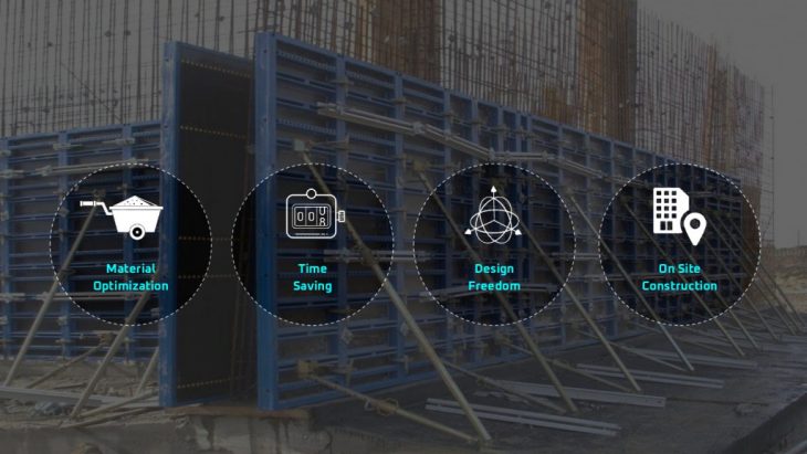
The background in below image is pretty much asking for a new system which is more efficient. So the 3d printing is solution to that because there is very minute material waste for formwork, faster, there is more design freedom and it opens up the on site construction possibilities. With all the mentioned pros there are some challenges to address too.
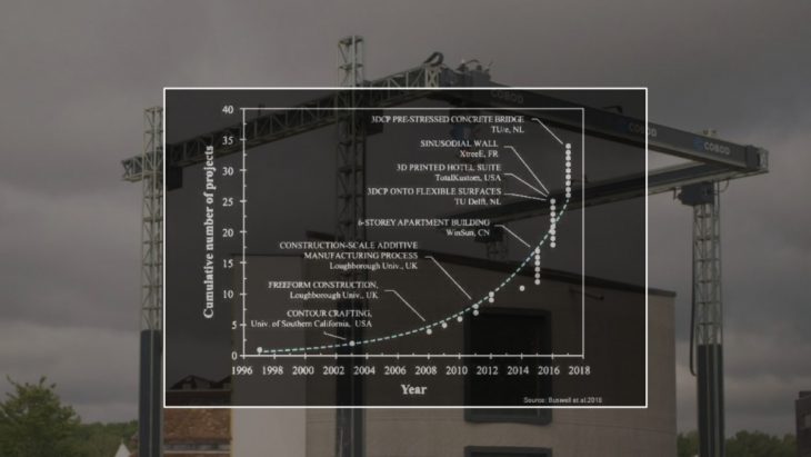
Context – Timeline of 3d Printing in Construction
For the proof of evidence that the 3d printing in construction is becoming the new normal. The graph below shows that every year more and more construction projects are breaking ground with the 3d printing technology. After knowing this fact the question arises here is that how many of the projects are using the data intelligence?
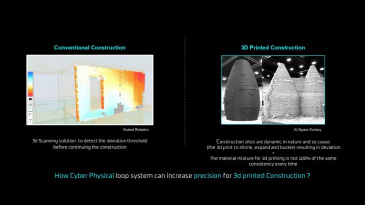
Error Mitigation – Conventional vs 3d Printed Construction
As we humans feel pain when there is something wrong in our body so similarly buildings also need to tell the pain and for that now scaled robotics is performing a role of a doctor. By looking at the gradient on the left image, the intensity of problem can be visualized. To achieve it we need the precision in sensing.
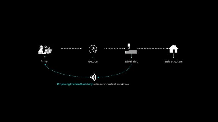
Objective – Proposed Workflow
The image shows a linear workflow vs the proposed workflow. There is integration of feedback loop for making the system more intelligent each time it perform any gets new data.
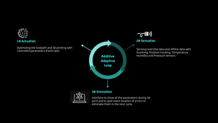
Objective – Reinforced Development Loop
To make the system intelligent enough to learn from its error there needs to be loop process as we learn daily. So this loop mainly consist of 3 main objectives.
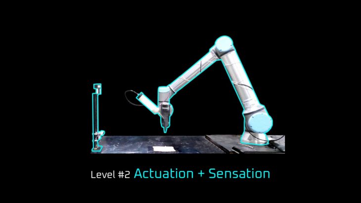
Road Map – Research Timeline
Here is the road map which shows the order of research. Starting from the point of linear workflow the development is divided into 3 levels and with each level there is more precision and integration of technology.

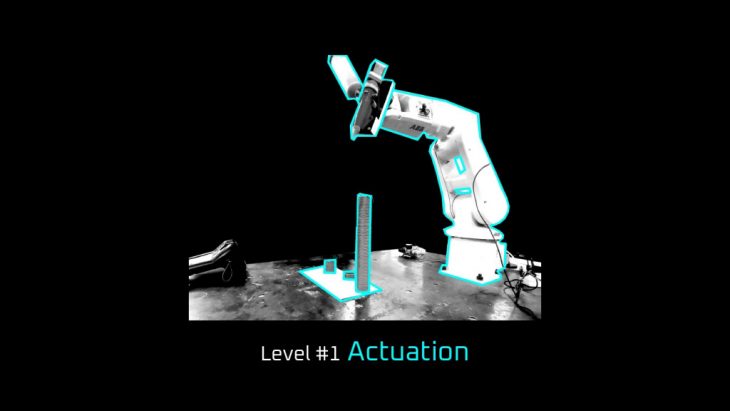
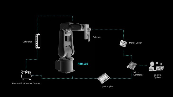
Setup – 3d Printing
The robot used in this phase is ABB 120. The goal here is to 3d print single layered column typology with higher height to diameter ratio.
Scope – Single Thin Layer 3d Printing
From left to right are the iterations in which the scale is increasing in terms of height but the rest of the parameters are constant which includes the same layer thickness of 3mm and diameter of 40mm

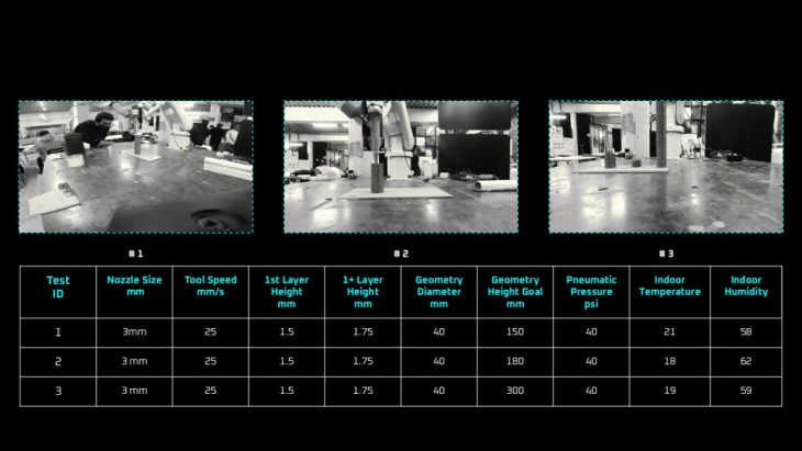
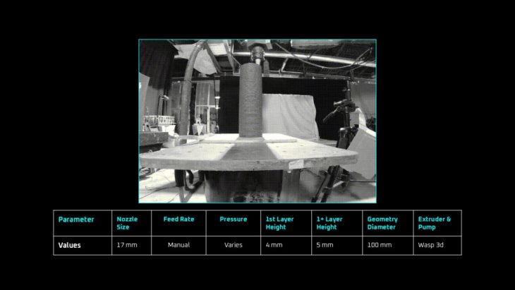
3d Printing – Hollow Column Typology
Here are the 3 tests with a table below showing all the parameters used in the process. The outcome geometry could reach the 300mm height with 3mm single layer printing while there is no fiber added in the mixture.
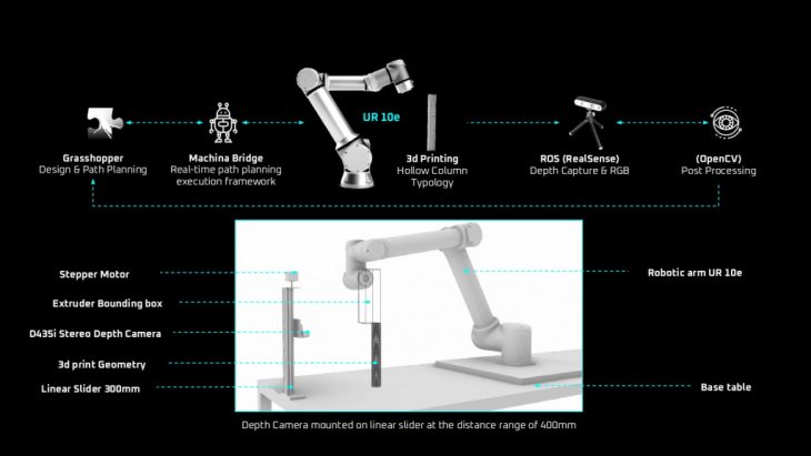
Setup – Adaptive 3d Printing
On the top is the workflow in which the communication between the robot and path planning system is described. Machina bridge make the action and response in real time. And in the bottom is the diagram showing the setup used in the process. The robot used in this test is UR10e which has built in force torque sensors in it. On the left in the lower diagram is the position of depth camera mounted on linear slider. The purpose of the linear slider is to align the depth camera with the 3d printing which help helps in the post processing of captured frames.
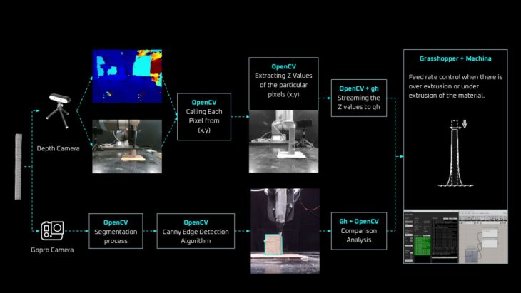
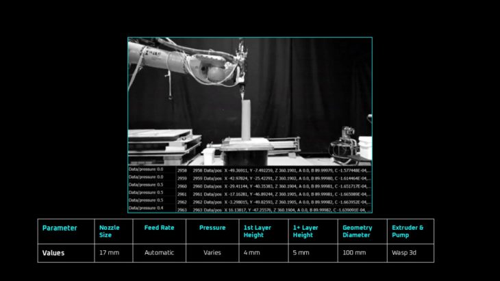
Setup – Realtime Sense & Response Protocol
There are 2 cameras. One is feeding the system with high resolution live stream to implement the canny edge detection algorithm which compares the area it detects and the the other is the stereotype depth camera providing with depth.
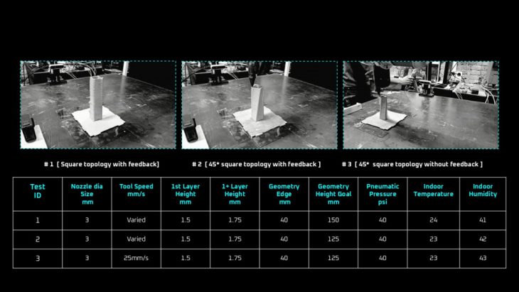
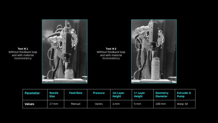
3d Printing – Hollow Column Typology with & without feedback loop
Here are some test with and without the feedback loop. In the first 2 test the system is intelligent to cover up the errors automatically and no interference is required. Where as in the 3rd case no implementation of feedback loop and the errors due to the inconsistency of material are evident in the geometric shape.
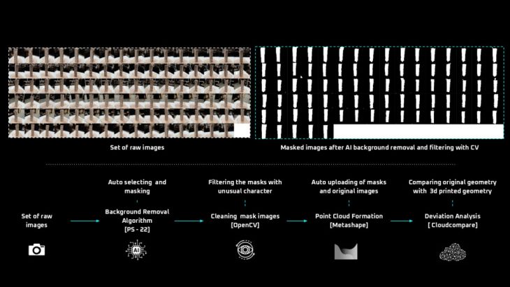
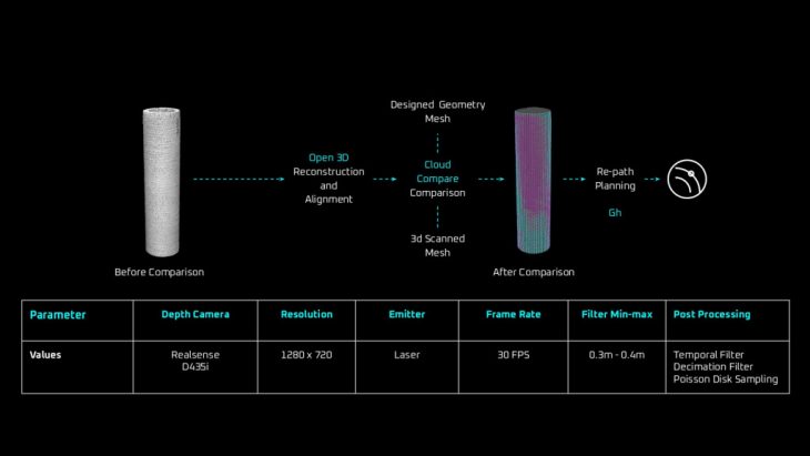
3d Print Post Analysis – Semi Automated Photogrammetry
As already explained the real time processing of data so there is also a post analysis in which photogrammetry is used to observe the deviation and to also quantify the performance of the system. Normally the method of photogrammetry takes lot of time in the processing of visual data before it’s being used. So the process is semi automated to the extent that it saves 50% of the time incase of large dataset by auto removing the background with PS 22 Algorithm and filtration process with computer vision.
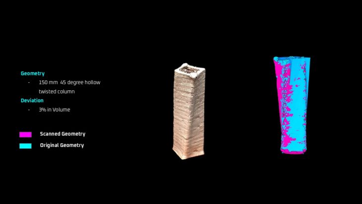
3d Print Post Analysis – Deviation Comparison
Here is the result of one of the 3d printed geometry with feedback loop. The 3d printed geometry when compare with original geometry the deviation observed is 3% in volume despite the fact that the material mix has inconsistency.
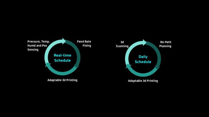
3d Print Post Analysis – Deviation Comparison
3d printing feedback loop is divided into 2 main categories with w.r.t time schedule. First is the real time feedback loop in which the feed rate is controlled in real time and second is the daily feedback loop in which the there is re-path planning on daily basis during the longer 3d prints.
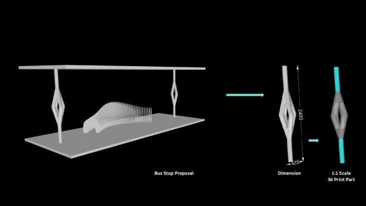
1:1 Scale Prototype Proposal – Bus Stop
To keep the main focus on the adaptive 3d printing process followed the same column typology in all tests. So here to integrate the cyber physical system on large scale there is a proposed a bus stop, took the chunk of the column to 3d print on 1:1 scale.
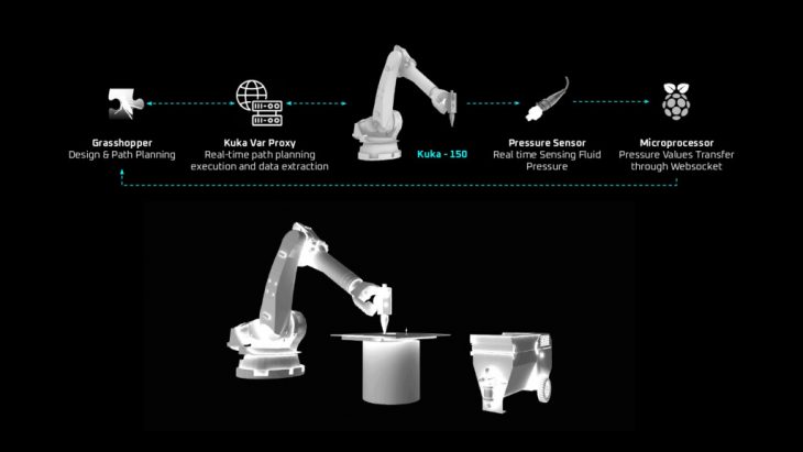
Setup – Adaptive 3d Printing
On the top is the workflow in which the communication between the robot and path planning system is Kuka Var Proxy. Kuka var Proxy is making the action and response in real time. And in the bottom is the diagram showing the setup used in the process. The robot used in this test is Kuka 150. The extruder and pump is from the collaborative company 3d wasp.
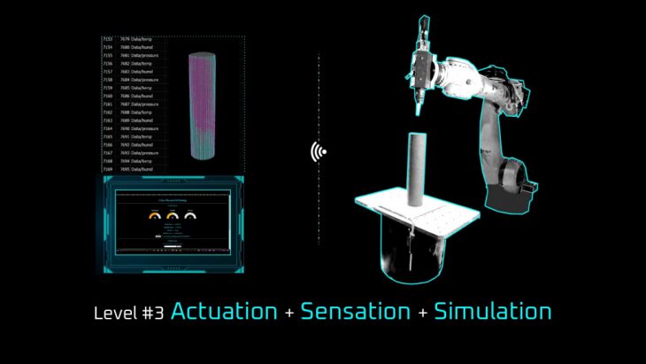
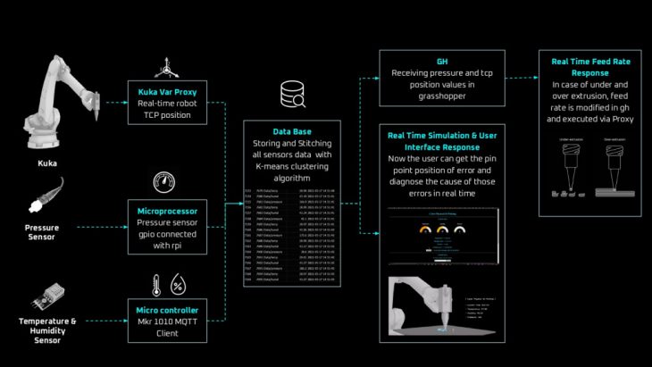
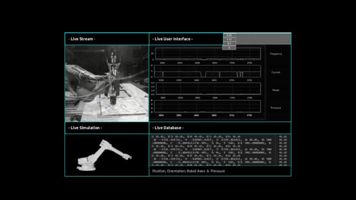
Setup – Real time Sense and Response Protocol
There are 4 inputs which include live position of the robot TCP, Pressure sensor values, Temperature and Humidity Sensor Values. All of the inputs are updated on the database. There are 3 bi products of this database. One is the use for feed rate control automatically in real time, 2nd is the user interface to analyze the data in real time and 3rd is the simulation in real time.
3d Printing – Column Typology with Optimized Mixture
There are 3 different test cases. Here in the case 1, 3d printed optimized material mixture and so there is no inconsistency and the target height with a single layer 3d printing is achieved. But said that this test involves manual interference.
3d Printing – Column Typology without Optimized Mixture & Feedback Loop
In this case column typology is 3d printed with a raw mixture and also with no feed back loop intelligence. The geometry in the left and the right both couldn’t reach the target height and were deviated during the 3d printing process. This is due to the inconsistency of material mixture and no feed back loop for correction.
3d Print – Column Typology without Optimized Mixture & with Feedback Loop
This is the 3rd case in which the same model is 3d printed without well prepared material but feedback loop intelligence is integrated and due to which the target height with single layer 3d printing is achieved. The best part here is that no human interference is involved during the process and the system corrects itself automatically with feedback response mechanism. The real time pressure values are used to manipulate the feed rate. More over now we also get the visual feedback in simulation format to take better informed decisions.
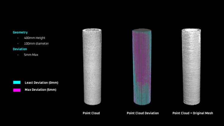
3d Print Post Analysis – 3d Scanning Setup
After doing the 3d printing, 3d scanning process is performed. The purpose of this is to analyze the deviation. The point cloud of the 3d print model is compared with the original geometry.
3d Print Post Analysis – Designed vs Printed Geometry
The deviation observed after the comparison is 5mm maximum. There are 2 color showing the max and min deviation.
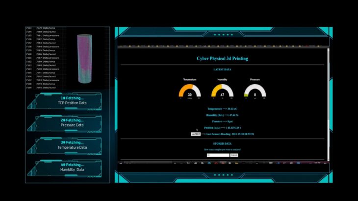
User Interface – Database Connection
As lot of data is extracted and stored on the database so now to utilize that database, the non technical user can even get the information in a user friendly way in graphics. On the right you have option to see the latest update in real time or you can analyze the past data with graphs. The user can input the no of sec. of data to be analyzed or the no of samples to be analyzed depending upon the computation capacity and time frame.
Industrial Application – Cyber Physical System integrated into IAAC Project
After doing the personal tests for the research with the developed system. The same system deployed on the research project of IAAC which is in the process of development for industrial requirement. This proves the integration possibilities.
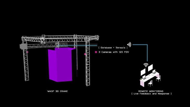
Industrial Application – Cyber Physical System integrated into Wasp Crane
The same system is proposed for the crane of WASP 3d to make the laborious work out of the way and 3d printing can be more automated with remote control action and response mechanism.
Ways the technology can Disrupt
Cyber Physical 3d Printing is a project of IaaC, Institute for Advanced Architecture of Catalonia developed at the MRAC-02 program in 2020/21 by:
Research Student: Mansoor Awais
Tutor: Alexandre Dubor, Aldo Sollazo
