Granular H20
Introduction
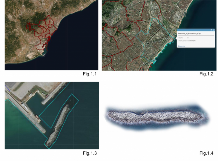
Seldom can architectural projects find an ocean front that has exposure to forces acting from a large body of water. Our study of waves becomes the manifestation of forces acting from a unique bed of rocks settled within the ocean that produce energy from the action of gravity and surface tension. Together waves find a resolution that maintains a level of fluid surface. Further, our proposal is designed to harness these forces that create waves by winds or the clashing water on stones, which reveals an untapped energy within the district of Sant Marti in Barcelona [Fig.1.2]. The energy created is known as pressure, where gravitational and surface tension forces become activated to produce waves in varying magnitudes of height. We face today new scenarios that reveal the power from wave action. Developing issues include the strength waves release that cause the movement of drag from the sand along the shore, causing erosion or damage to coastal lands.
Granular H20 is a project of IAAC, Institute for Advanced Architecture of Catalonia developed in the Masters of Advanced Architecture 2020/21 by Students: Jose Rigoberto Moreno, Kajal Unahariya, Karthy Krishna, Chirag Shah and Faculty Peter Magnus and Edouard Cabay
Design Problem: Making Energy Visible
An initial understanding early in the development of this design proposal was to observe an everyday home device, in order to make energy visible. The home device selected for this proposal is an ultrasonic humidifier. The device is to be interpreted through an intense mapping criteria, which reveals means of drawing the effects of energy releasing qualities as a time/energy vector. [Fig. 1.5] Figure 1.5 demonstrates a drawing study of the formal parts in section and in plan view to reveal the components. This careful study of the assembly of parts provides a realization of instruments that are perfectly compartmentalized, elongated and housed within the framework of circuitry.
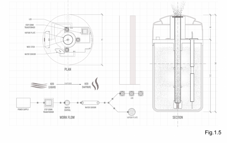
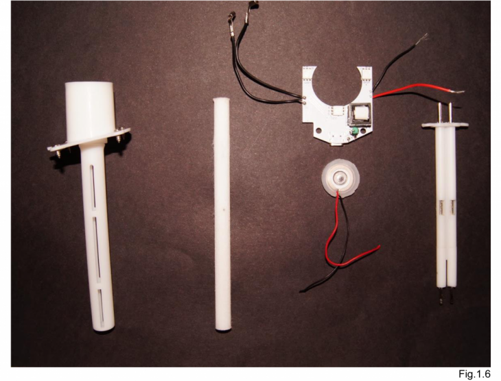
By dismantling and modifying the device our studies in realizing the effects of the energy became clarified as a measure of time, weight, count. This basis of remaining parts became a transition point into optimizing a design proposal that extracts the energetical phenomena. Further, the energy visibility translated into determining points of interest and focusing on changes that would maximize the amount of time. [Fig. 1.6]
The main components in Fig.1.6 reveal that by creating a new storage container for water, allows for all of the parts to function without any problems. Additionally, a dry/wet wick determines the release for intervals that unlock the air mist release. From this observation it is clear that the heat plate remains constant with power to await contact with water. The heating plate becomes exposed directly above the water pump and before the air nozzle release. The logic of the ready-made object informs that the steam escaping the water container travels through a sequence of parts that maximize the time, vaporization and amount of pressure released into the air. Additionally, the bare minimum of parts taken from this ready-made object reveals that the phenomenon, which releases this air mist is an energy of complex assembly.
Energy Phenomenon
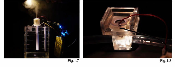
Since the humidifier is modified [Fig.1.7], it becomes clear that water is our main control device for the newly interpreted device. Various attempts to isolate parts were attempted, and proved beneficial in our study. This includes retaining the ultrasonic heating plate for vaporization qualities, fed by a water supply tube below [Fig.1.8].
By creating a low-technology air pressure fog device, our design proposal can translate the energy found in water to create a granular system that synthesizes the effect of fog.
Phenomenon Designed
The energy phenomenon observed from the ready-made object allows our design intentions to become centered on air pressure. Where an air nozzle is fed water by an air pump to synthesize a similar effect found in the humidifier. By realizing that various parts needed to exchange the inputs that create vaporization, our design interventions became realized as feasible through low-technological means.[Fig.1.10]

The designated assemblies became refined further through experimentation. Where values that are necessary to exists must acquire their setting to change the state of water through a sequence of events. Therefore, an independent device is imagined through a series of main components of plausible use, and configured to reveal its energy producing qualities. [Fig.1.11]
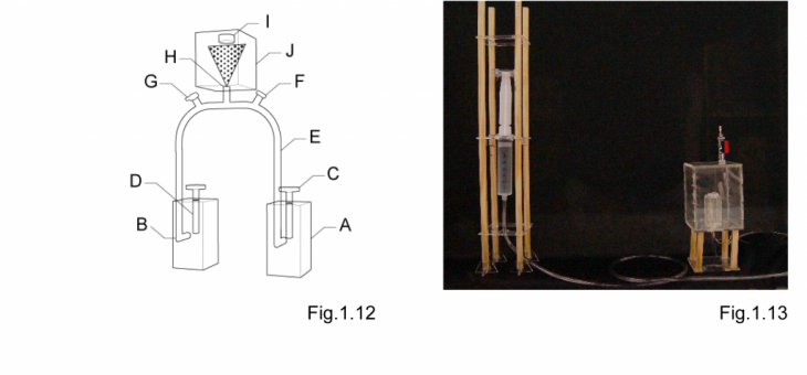
In order to conclude the findings of the design phase for this experiment, it must be noted that the device is not designed to re-create the same effect. Rather, the designed intentions are simply to realize ways of synthesizing the air mist through separate chambers.[Fig.1.12] These chambers are controlled variables that contain one part water and one part air. By creating custom designed parts for the device, our design allows flexibility to monitor new variables of water capacity, flow rate, and direction to pass the energy through specific paths, along their vertical or horizontal lines of exchange.[Fig.1.13]
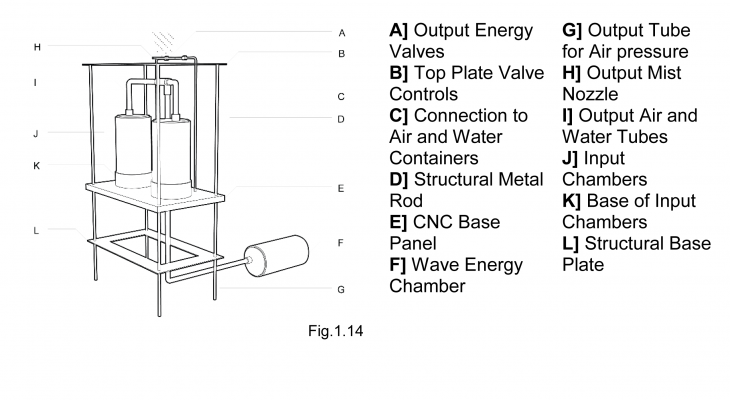
The final results in this phase reveals that energy as a phenomenon through air pressure, can be realized through a series of networks. Primarily because it is in contact with new devices that exchange the state of the input material [water]. The objective of this phase is to effectively recognize all of the necessary components viable to imagine such instrumentation. Therefore, it becomes clear that isolating separate chambers for air and water is the most effective means of controlling the output. [Fig.1.14] Additionally, the output nozzle effectively simulated the same effects in previous design iterations. Thus, this element is certain to become carried over in the design.
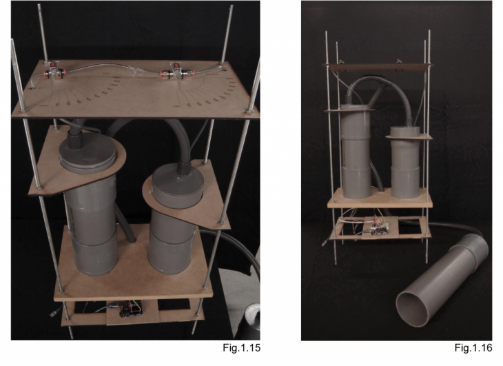
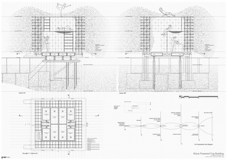
The final design intervention for a pressure building device that releases fog was constructed with new parameters.[Fig.1.15] This design iteration includes a measure for the release valves both for water and air. Primarily, this element of the design is designated to visualize the state change of water output, while finely adjusting the amount of air pressure for the intersecting air valve. The entire structure is constructed with wooden platforms to synthesize a construction support.[Fig.1.16] Metal threaded rods are utilized to connect with a hex nut to the support floors. A main base underwent CNC milling to fit PVC pipes that were sealed air tight. The continuation of the tubes that intermingle are found above the air and water chamber. Where at this point the nozzle is found at the very top, intersected by the release valves for each corresponding chamber. A new intervention at this point of the design is the introduction of a vertical wave chamber that is found to be connected below the air chamber. The expectations of this new chamber is to create an input for self-sufficient means of collecting air pressure.
Designing For Air Pressure
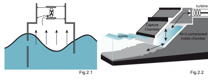
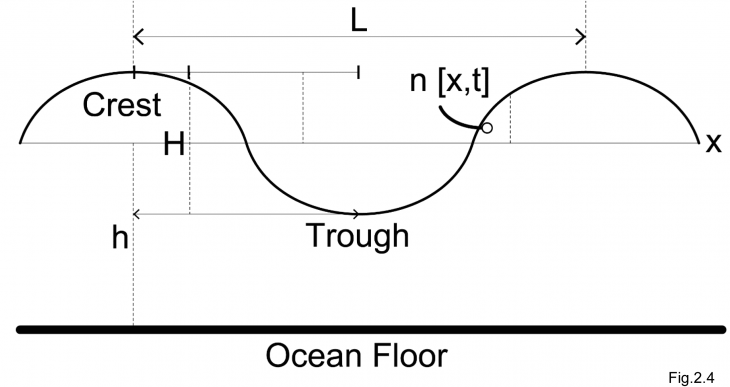
In order to establish an overview of existing projects that influence the design proposal, we must make note of the projects within science, nature and art. Oceanic waves are currently, being used to capture and maximize air pressure, which becomes accessible by intersecting new means of designing for energy harnessing. [Fig.2.1, Fig.2.2] Figure 2.1 depicts a vertical water column placed in the ocean to circulate air from the oscillation of waves. Additionally, Figure 2.2 is a combination of the same idea, but rather it is integrated into the horizontal direction to push the waves back to increase force. The exchange from water waves through the use of a capture chamber is imagined and significantly influenced for the final proposal. Where our hypothesis is based on designing a wave chamber that allows for a resistance wall to push back the waves and based on the chambers air tight qualities transfer’s air through a vertical path.
The most resilient aspect of the references are shown by wave chamber system[s] that collect air by low technology methods. Rather, the chamber is not only pushed by the wave’s pressure through oscillation, but also by means of exchange from one chamber to the next.
Continuing with the influence found in nature, our proposal examines the chambers found in geysers and their natural phenomenon related to systems of pressure. The most appealing aspect is the geyser’s ability to grow from a natural system below the earth. The immediate opportunity to understand the methods of releasing steam is induced by pressure exchanged through contact with magma chambers. The soil as a thermal membrane offers the formation of natural forms created by cavities that reveal this phenomenon.
Since the threshold of water is affected by pressure and air flow emitted by the release valve, it is essential to intersect the air mist nozzle at the best possible point. Therefore, a third chamber must be created to collect air pressure. This will allow for controlling the release valves through settings that are measured to transform water into mist. The control device in this final design will be the release valves for water and air, which is connected to a pressure chamber. This focus involves tapping into an environmentally natural resource, which provides such abundance of energy. Logically, the project is at this phase being designed to function as a device capable of collecting and releasing air pressure. Yet, the syntheses of this device iteration proves that a system can be designed to collect self-sufficient energies from the assistance of ocean waves.
Waves occur in a variety of sizes and forms, and our study is dependent on the magnitude of the forces capable of being controlled through a designed device. In order to coordinate the forces found on our site, a device must be designed to quantify a value that provides rational for pressure production.
Calculating Pressure
The length of the wave provides an idea of the magnitude of the forces acting horizontally by the wave[s]. An example, the longer the wave, the more significant gravity is in relation to the ocean surface tension. This is critical as the water depth over which they are propagating is critical in understanding the extents of the structure for the wave chamber. Pressure building parameters, such as wave-induced water velocities and accelerations, can be determined theoretically from these quantities.
The rule that there are 0.433 psi per foot of water informs that we can calculate the psi of the ocean wave height, or alternatively, the rule that every 2.31 feet of water creates 1 psi. By using the formula for pressure, where h is the height of the water surface in feet and P is the pressure in psi. Therefore, by inserting the height measured in the last step into the h position in the formula and evaluating the data. For example, the psi created by 100 foot ocean wave can be calculated using the following formula:
P = 0.433 x [wave height]
P = 0.433 x [100 ft]
P = 43.3 psi
Pressure = pounds per sq.inch
Ocean Wave Characteristics
Figure 2.4, illustrates a two-dimensional schematic of a wave propagating in the x direction. The length of the wave, L is the horizontal distance between two successive wave crests, or the high points on a wave, or alternatively the distance between two wave troughs. The water depth is denoted by h and the wave period is denoted by T. This informs how our design may formulate the speed of the wave, called the celerity, C, which is defined as C=L/T.[Fig.2.5]
Expected Design Problems
Waves throughout nature rarely appear to look exactly the same from wave to wave, and they do not always propagate in the same direction. In order to eliminate unnecessary measurements, a distance sensor device [Fig.2.5] is selected to capture the surface elevation offset by the size of the crest on the wave. Where n, serves as a function of time placed on a platform in the middle of the ocean.
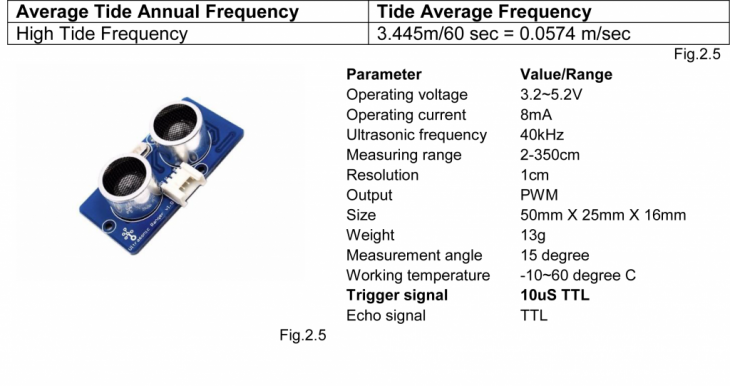
Our data reveals that there is a great amount of randomness in the sea, and statistical techniques must assist in conveying the data. The expected order of the sensor device measures by trigger at a speed of 10 milliseconds.
Measuring Waves
A device is designed to record important parameters that describe the quality of the waves based on their length and height. Since our device is to be placed in the ocean, this wave chamber becomes subject to wave action. These factors inform not only our design intentions, but also our final design for a radical home that captures air pressure. Therefore, development of a wave height device is depicted in a simple illustration [Fig.2.6]. The calibration device must be a large vertical volume that allows to record data of varying wave heights.

The main device of measure is based on creating a structure, and since the ocean is constantly displacing the surface water an ultrasonic sensor is utilized to measure these changes. Upon beginning the Arduino recording, the sensor will assume that the displacement of the ocean wave height is low or high. The consecutive numbers recorded will provide details about the change in wave height. Additionally, each cycle of data recorded is designated by the sensors specifications at 10 milliseconds per sensor reading. Since the waves are passing through the field of view for the sensor, we can consecutively record the passing wave heights for each value recorded.
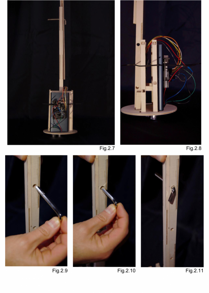
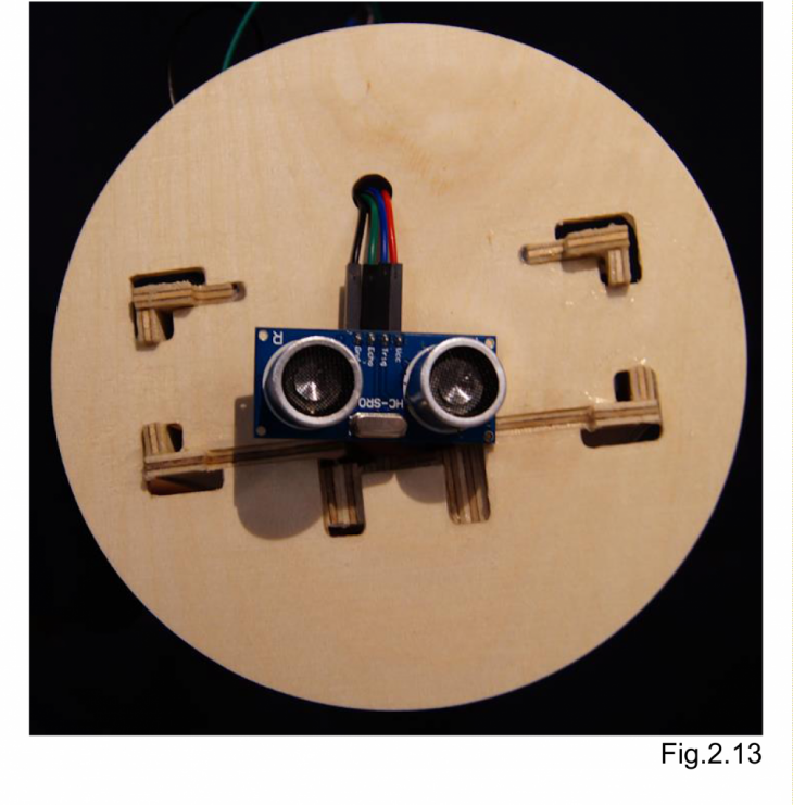
In order to record the wave height, our instrument is incased with a combination of hardware devices. The device includes a CNC milled plywood housing structure, which allows a battery pack to power the Arduino Uno, SD card reader, and Ultrasonic Sensor.[Fig.2.8] Since the sensor requires a fabricated structure, it would be natural that clearance for the sensor could only be reached by a cantilevered structure.
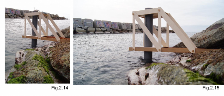
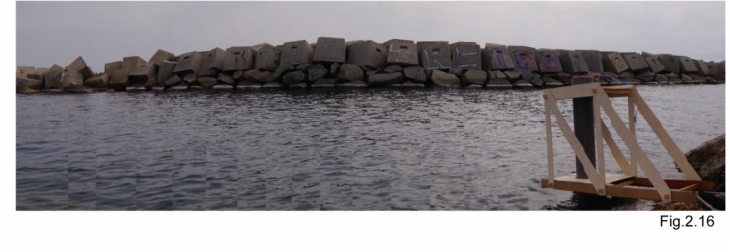
This structure acquires a platform that is traversed by a lateral connection on each side. A platform is cantilevered to allow for a tube to run vertically into the ocean. [Fig.2.16] This tube allows access for the ocean waves below and clearance above for the ultrasonic sensor. With these parts the device can provide data for each cycle of wave heights read by a stand-alone sensor.
Data Processing: Design Hypothesis
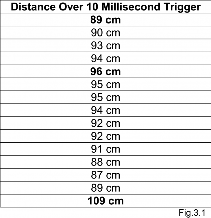
The wave height device is designed to constantly capture a body of water for the changes in waves that records the varying wave heights. If 1-foot of water increases we can assume that 0.433 psi of pressure will become created in the wave chamber device. Additionally, it requires 2.31 feet of water to create 1 psi of air pressure.[Fig.3.0] From this idea we can calculate the psi values acquired from the vertical wave chamber sensor. Our data recorded reveals that there is at minimum an oscillation of 20cm that varies from ocean waves.[Fig.3.1]
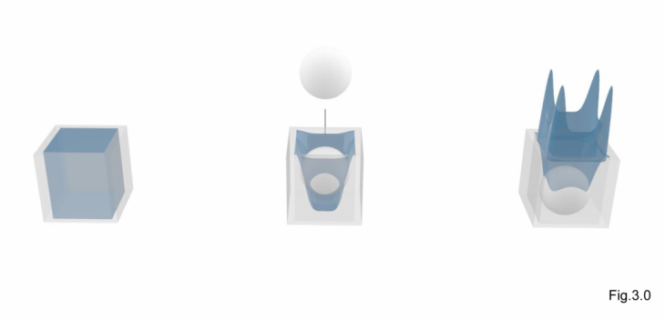
Figure 3.0 demonstrates the still water for a 1 foot of water, which acquires a constant pressure of 1 psi. If the body of water is oscillating then it is believed that gravity for the uniform body of water in the ocean is under tension. In order to simulate this concept, imagine a sphere is dropped into 1 cubic foot of water. The 1 psi would increase due to added weight of the sphere. This proves that there is energy being generated because the waves are constantly undergoing a formation of a crest and a trough.
Comparing Data
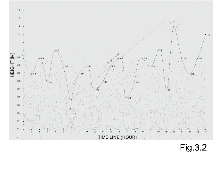
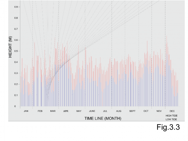
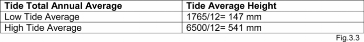
Further, we can compare data retrieved from the ultrasonic sensor, where these figures can become compared with existing data.[Fig.3.2] Now, we can take the values from the pressure formula and translate these figures to compare the low tide and high tide data offered by the Port of Barcelona.[Fig.3.3]
Alternatively, we can synthesize the production of pressure by averaging the low tide and high tide figures on an annual basis. The values averaged allows our device calibration data to become compared all year long with any value taken from the date of our experiment. Based on our results for the given day, we can compare if the values are within reach of producing the equivalent values for pressure.[Fig.3.3]
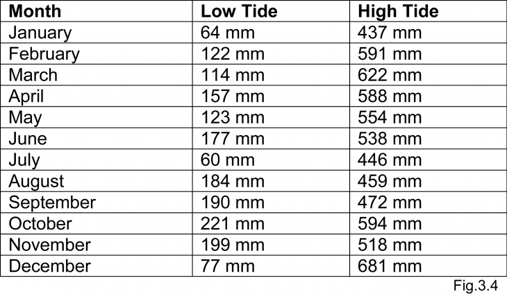
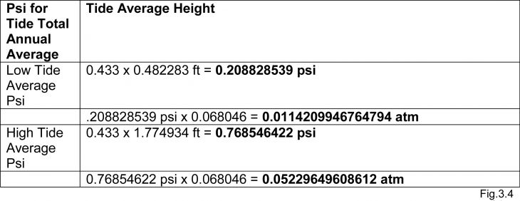
Additionally, the low tide average Psi value is within 0.20psi, which refers that the ocean tides would be able to rise to a height that would allow for .20psi of pressure to become generated. For the high tide average a Psi value of 0.76psi can become generated without any design intervention. This implies that the waves rising to a height would be capable of producing pressure by the crest and trough of the waves alone.[Fig.3.4]
Conclusion
It is worth noting that the wave chamber system is possible to capture air pressure with the ocean waves. Even if waves would not oscillate up and down, the depth of the ocean obtains pressure in the vertical axis. Yet, the moving body of ocean surface has more potential for a stationary system. Considering the elements needed to harness the wave’s energy into air pressure, we must consider that a nozzle size, along with a psi is almost definite in resolving. Therefore, it would critical to assume that a 30 psi is needed per nozzle and that the air pressure containers must facilitate a value capable of providing energy to each nozzle situated in the design. While the system is a solution to realizing the energy of waves, it is also worth investigating a system that maximizes wave characteristics due to wavelength and wind speed. Although, speed is recognized as an important variable in the system, it becomes arbitrary to complicate the equation for pressure.