DEFORM TO FORM
1. FRAMEWORK
“Hands-on experience is the best way to learn about all the interdisciplinary aspects of robotics.”
– Rodney Brooks
RESEARCH TOPIC
Can we create room for plasticity & playfulness in a robotic process?
PROBLEM
The problem we are facing is based on the deformation in the additive manufacturing process with clay. Through machine learning we want to study the offline programming one way-top down-rigid way of working enabling creativity through real time bi-directional workflows.
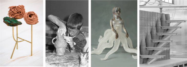
STATE OF THE ART
We can take these 3 different examples on how the process of printing in clay can become an expression by itself, adapting to the external surfaces or objects and playing with the embedded materials.
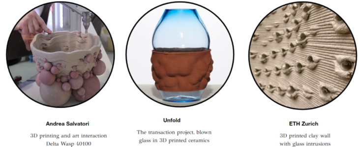
Source:
http://unfold.be/pages/the-transaction-project.html
/
https://www.youtube.com/user/wasprojecteam
AIM
VALUE PROPOSITION
A flexible, responsive system of construction
facilitating a blend of human somatic design and algorithmic design
embedding real-world objects into robotically-printed forms
2. WORKFLOW: CONCEPT & DEVELOPMENT
PROJECT OVERVIEW
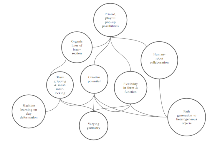
The project sits on three main planks, which will be described in this blog:
i) path generation in response to heterogeneous objects – scanning objects placed on the print bed and generating a robotic printing path that acknowledges them geometrically
ii) machine learning on deformation of the clay – clay prints may deform while trying, impacting the final geometry of the piece. Analysis of deformation and machine learning algorithms were applied to anticipate deformation so it could be allowed for in the printed geometry.
iii) varying geometry of the macro product. Any geometry of 2.5D tile can be printed, allowing flexibility in the form that results when these tiles are placed together.
Each of these three base tenets combines with the others in various ways to produce characteristics of the project. These include:
- Human-robot interaction, with the human placing the object and the robotic path incorporating that into the printed form;
- Object gripping and mesh interlocking, facilitated by the prediction of deformation from machine learning processes, and the variable geometry of the 2.5D tiles;
- Flexibility in form and function, where the variations made possible by being able to place any object/s in the tile, and having different shapes of tiles, allow eg. a façade with different levels of light permeability at different points, as required by the client and the purpose
- Creative potential unlocked by all three of these planks in combination.
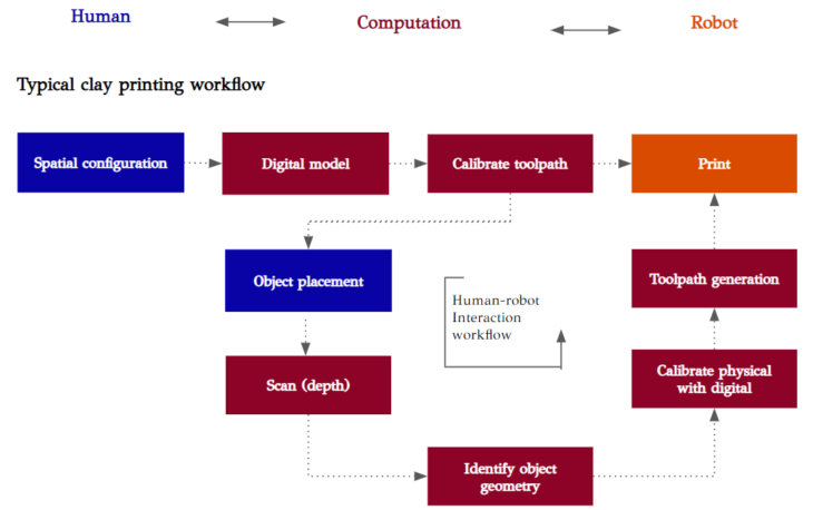
A typical clay printing workflow involves the top line of the diagram above: a human creates a spatial configuration; a digital model is created and toolpath calibrated using computation, and a robot prints the piece.
Human-robot collaboration: In this project, we introduce an iterative loop between the calibration of the toolpath and the printing, in which a human places an object; then computation provides the services of scanning, identifying the object geometry, calibrating the physical with the digital and generating another toolpath, before the robot prints the geometry.
PROJECT SET-UP
ROBOT SET-UP
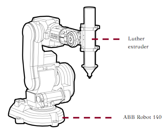
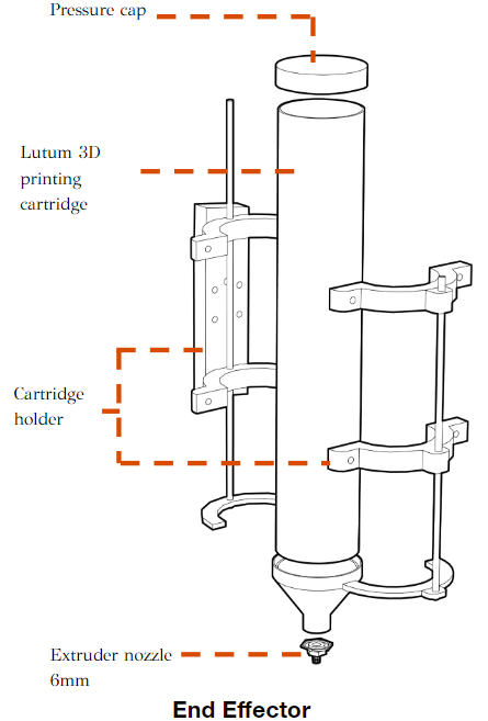
The Lutum 3D cartridge works with pneumatic air pressure, attached to the robot with a ply frame.
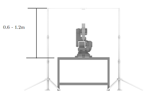
DEPTH CAMERA SET-UP
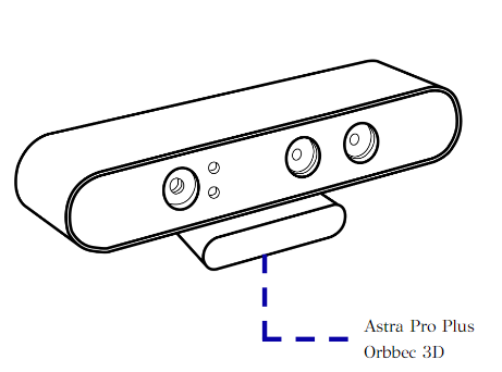
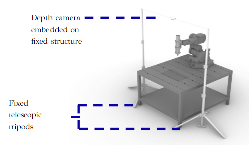
For the depth camera research we used the Astra Pro, fixed parallel to ground and square to the printing / robot table. The camera is best used at a height of 0.6 = 1.2m above the print bed.
OBJECT DETECTION
The gif shows the depth camera feed of a human placing objects on the print bed. The physical process of positioning the objects facilitates a spatial design process and adjustments.
The depth camera then captures the print bed and objects to be fed into a script calculating geometry and toolpath. In this example we used semi-transparent coloured circles to be placed in the tiles, but with this method any geometry of the object is possible.
SCANNING PSEUDOCODE
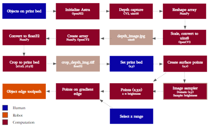
Above is the pseudocode for the three-step scanning process. The colourway indicates the human-robot collaboration and interaction.
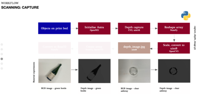
We wrote a Python script to capture the depth image. The Astra Pro is connected to the laptop and initialised using OpenNI2, and a depth image captured as a uint16, using OpenCV. The array is reshaped with NumPy, scaled and converted to a unit8, again using OpenCV, to allow it to be viewed. It’s saved as a .jpg. Examples of the depth images of some common glass objects can be seen above.
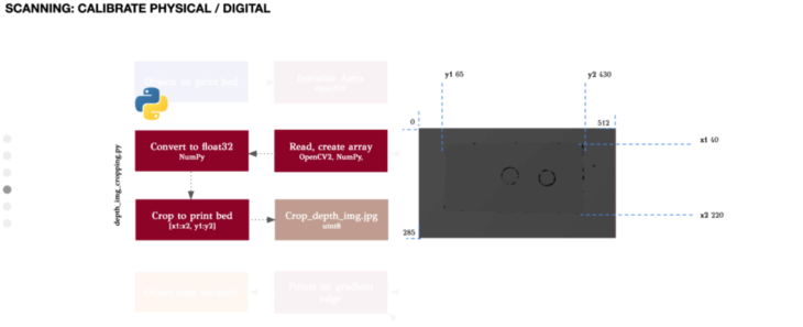
The depth image has been captured, but includes a certain amount of the table as well as the print bed. To allow calibration from the depth image to the digital geometry of the tile outline, we need to have the frame of the image cropped to contain just the print bed. So a further Python script reads the image with OpenCV and creates an array using NumPy, then converts the image data to a float32 format. The image is cropped using OpenCV by manual identification of the x1,x2 values and y1, y2 values of the edges of the print bed.
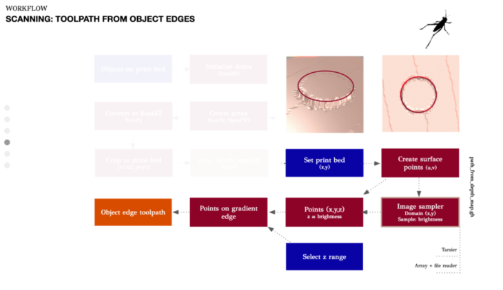
Finally a grasshopper script identifies the toolpath around the edge of the object. To do this, a rectangle is set manually with the same x and y values as understood from the previous Python script, so it is the same size as the physical print bed. This rectangle is covered in points, a surface created from it, and then it is textured with the cropped image fed into the image sampler. This gave a set of points, each with an (x,y,z) value. The script then contained the option to manually select the z range, allowing the slope at the edge of an object to be detected. This method has the advantage that the depth image could be taken from any height, rather than needing to fix the camera at a certain height, and build a frame.
The points on the gradient edge of the object are then absorbed into the main robotic toolpath.
Other methods investigated for bringing the image into GH were were Tarsier, which allows point cloud streams to be fed into Grasshopper in real time, but it seemed this worked mainly with Kinect cameras. Another option would have been to export the image as an array in .csv format, in which the xy grid were the image pixels, and the pixel value the depth, or z value. The .csv file could then have been imported using the file reader in Grasshopper.
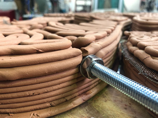
CLAY AND 3D PRINTING
The process of working in clay, 3D printing and baking processes bring the following implications:
Clay working implications
Red clay ~ 25% water/
3DP clay + 2% water
Homogenous mix, avoiding bubbles and air contact (20’)
Dry shrinkage: 7%
Kiln shrinkage: 0.5%
3D Printing ABB 140 + Lutum 3DP cartridge
D-nozzle: 6 and 10mm
Layer height: 5mm
Print speed: 13mm/s
Pressure: 2.5 bar
Base: MDF, plastic bag, wet clay
https://vimeo.com/730952616
BAKING
In order to keep our pieces structurally stable and to rigidize them homogeneously we follow the process of firing them inside a kiln. We also tested different materials proposed in our future design to know their behavior on the process.
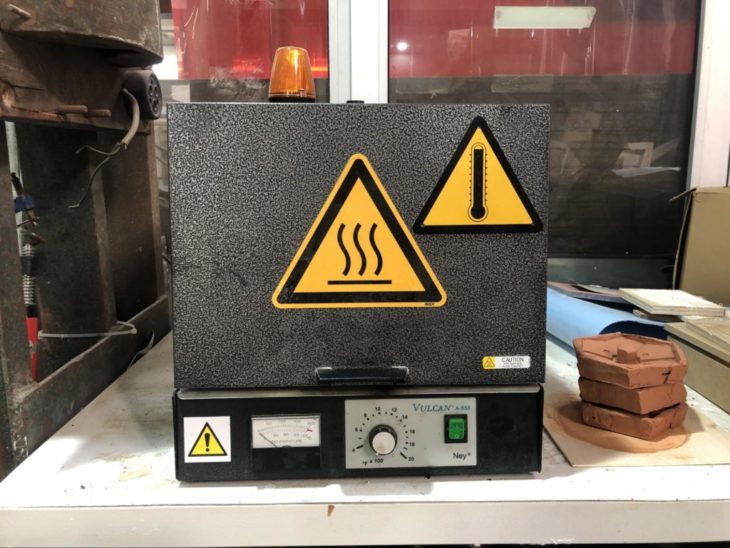
Kiln
Vulcan A-550
Clay firing rate: 970-1055ºC
Max. Vol.: 23x23x18cm
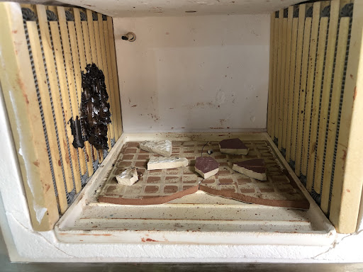
This is the kiln setup, with tiles on the base to prevent from melting glass over the bed.
Samples
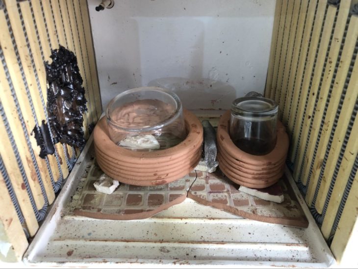
D10cm clay cylinders
2 glasses
SS mesh
Firing schedules or curves for glass and clay present different heating and cooling temperature ranges as you can see below:
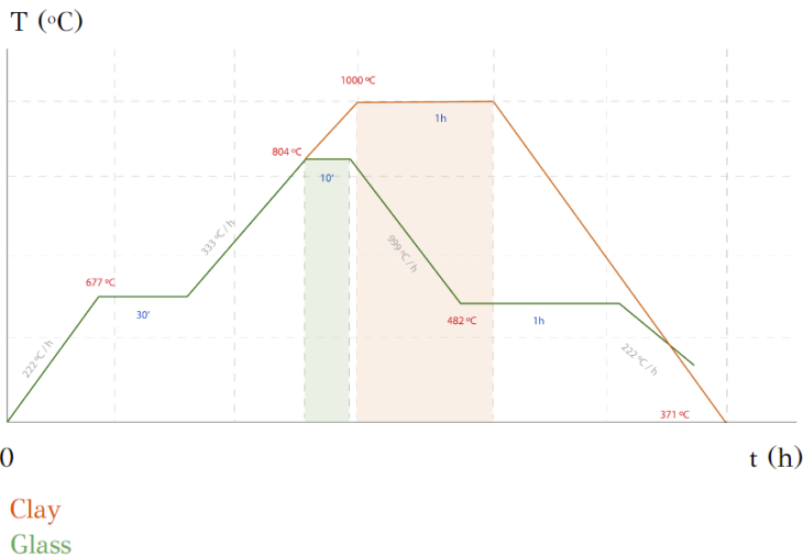
Results
Clay not cracked
Glass melted and then cracked
SS mesh lost in rigidity
Glass not stuck onto walls
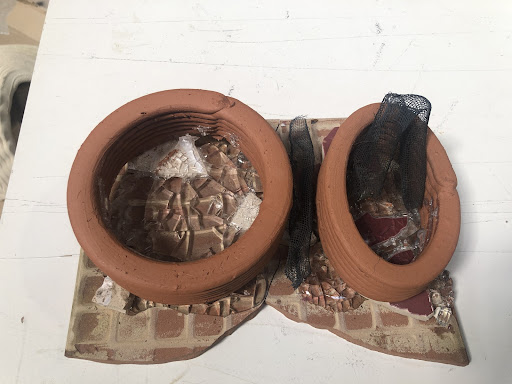
The results show how we should first bake the clay at its own firing rates and then fire the glass on top of the clay to melt it at different temperatures and timings to prevent cracking, despite the glazing effect looking appropriate.
MACHINE LEARNING
A response to the need to have inserted objects. Yet we are left with the problem of shrinkage and how to make sure it will not leave a gap around the inserted objects. Shrinkage has been always there when ever 3d printing with water infill materials like clay and concrete. Always it had to be dealt with , with a lot of trial and error. Since it is touching the core of our project we approached to solve the problem using machine learning.
We used a machine learning algorithm to train a predictive model.
We used Owl, a grasshopper plugin to build our script.
We used a Regression technique.
Regression is a technique for investigating the relationship between independent variables or features and a dependent variable or outcome. It’s used as a method for predictive modeling in machine learning, in which an algorithm is used to predict continuous outcomes.
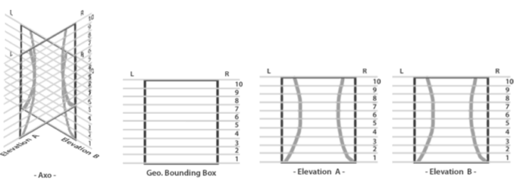
To simplify the problem we trained the model using 4 sets with 8 shapes each.The 8 shapes are divergent and distortion of a perfect circle in the minor access to have an ellipse.
The sets had 5 cm , 10 cm , 10 cm and 15. Although two sets started with the same diameters they still had different shinkages per layer.
Check : Fig. A
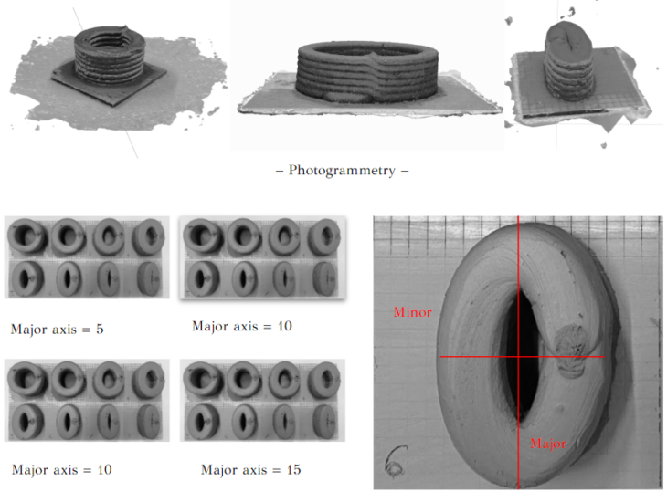
– Fig. A –
Distortion measurements
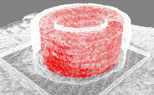
Then after printing our samples we scanned them using photogrammetry, getting the model results we compared them to the original geometry to see the difference between the CAD model and the after print and measure the distortion using this steps.
– Reorient photogrammetry model & overlay with CAM model
– Front view reveals minor axis / Right view reveals major axis of geometry
– Measure absolute values of layer offset, per layer & per edge
– Center of model located on node in 3D environment, so:
|Left edge:
- Shrink ? -ve
- Swell ? +ve
|Right edge:
- Shrink ? +ve
- Swell ? -ve
The Data :
The collected data was organized in excel sheet, which turned to csv file.The file is feeded to the algorithms and from the other side you get the displacements for each layer to be ofsted to have a deformed model that will shrink in place and get a correct printed geometry.
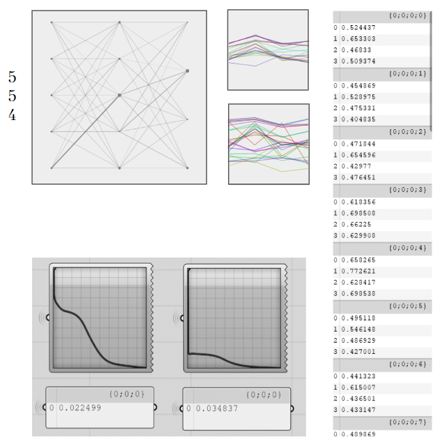
Panel errors
– Backpropagation error = 0.022199
– Evaluation error = 0.034011
Applying the predictive results to the geometry :
3. CASE STUDY
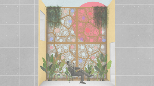
DESIGN PROPOSAL
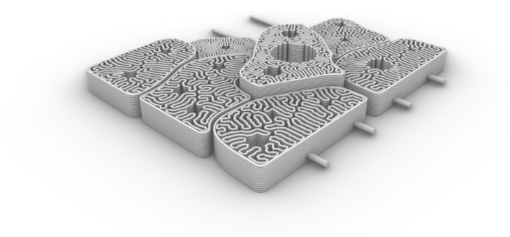
We proposed a construction sample where we could 3D print some pieces in clay, mix them with different materials to finally build an organic puzzle with different applications. The idea brings removable and stackable bricks, guided along a metal rodded structure that will be bolted to the main wall of an existing building.
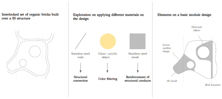
Differential Growth
We are using an algorithm based on natural processes of growth. This fills the space within closed paths formed of connecting both inner and outer lines:
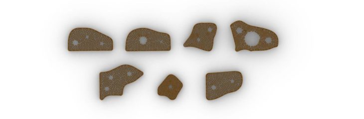
PROTOTYPE DESCRIPTION
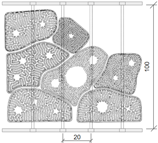
Our prototype will remain as a sample of part of the construction we propose with 1x1m final dimensions.
7 adobe bricks built along the structure
(Connected with rodded structure + metal mesh + acrylic and glass objects).
Bricks present different characteristics in shape and mesh interlocking:
Sample of structural façade
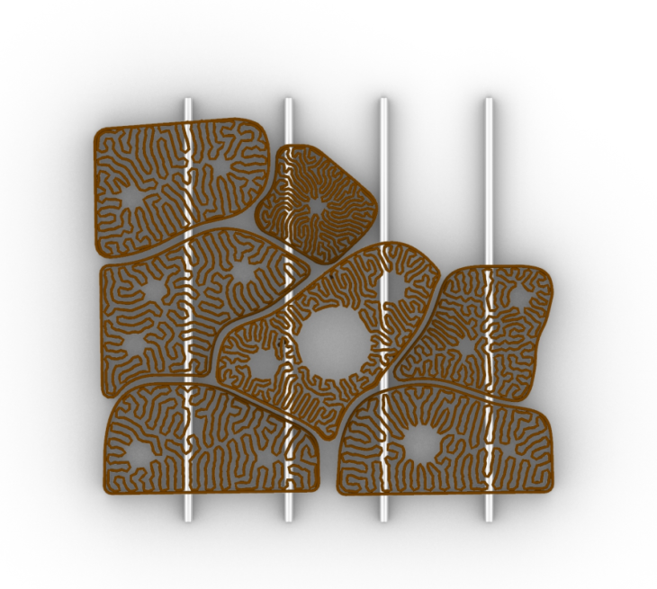
(Rodded structure + metal mesh + glass). Rods are bolted to a metal or wooden structure.
Size: 1x1m
Average bricks
Size: 40x20x10cm
Weight: 6.2kg
Printing time: 2h15’
Nb. of layers: 14
Drying time: 2 weeks
Prototype on wooden structure
The final prototype will be presented on a wooden frame, bolted on top of an acrylic plane to show the visual effects of colors of lights and shadows underneath.
ROBOT TOOLPATH
The robot tool path included two printing lines on every layer: first, the inner infill pattern and then the outer line.
Next, you can check the process of printing on the 6 main pieces of the prototype:


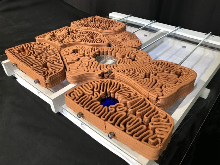
PRINTING AND ASSEMBLY PROCESS
This is the whole process of printing and assembling the prototype:
Final assembly
This is the final result of the assembly of the prototype:
Bolted connection
M10 SS rod
M10 washer + autoblocking nut
M5x40 on the structure
Light visual effect
Reflection of light and shadows from both top and bottom
This was the entire process:
4. NEXT STEPS
GENERAL INSIGHTS
Immediate insights
– Thicker layers next to rods, and on the outline
– Lower layer height with smaller nozzle
– Bake tiles, then bake with glass
– Make holes on mesh for layer connection & settling
– Introduction of different patterns & algorithms for space-filling
Future project progression
– Depth camera workflow enables objects to be embedded with 3D design variation
– Utilization of waste objects without the need for energetically expensive recycling processes
– Airflow and light penetration can be flexibly designed as per client requirements
– Robotically-fabricated stained glass…? For the environmental temples of our future
Shadow & color patterns cast by light through brick

ALTERNATIVE DESIGNS
Deform to Form is a project of IAAC, Institute for Advanced Architecture of Catalonia developed at Master in Robotics and Advanced Construction, in 2021/2022 by:
Students: Andrea Nájera, Alberto Martínez, Grace Boyle, Abanoub Nagy
Faculty: Alexandre Dubor, Marielena Papandreou
