ABSTRACT //
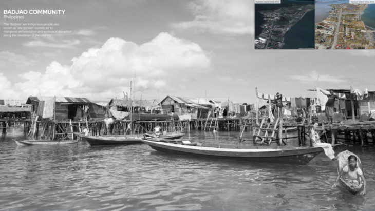
The ‘Badjaos’ are an Indigenous tribe, living along the coastlines of the philippines. With rapid growing cities, indigenous communities have been pushed out of their original land and adapted to the times similar to the badjaos, originally coming from fishing villages and pushed to live as sea gypsies. these informal built dwelling structures (housing + fish farms) are highly exposed to climate based catastrophes (typhoons), which creates a vulnerable socio-economic status of the bajao community. our goal was to develope a natural typhoon resilient barrier that provides a protective layer to the coastlines of the philipines. this has lead us to a modular lattice system, that provides different scales of dwellings within it and enable the badjao community to adapt, adjust and grow in the future. team: Neil John Bersabe, Maria Papadimitraki, Mahmoud Ramdane, Clemens Russ, Daniyal Tariq
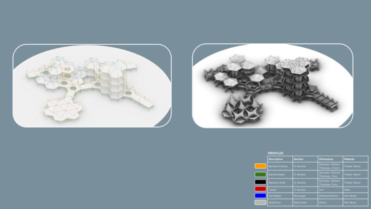
STRUCTURAL APPROACH //
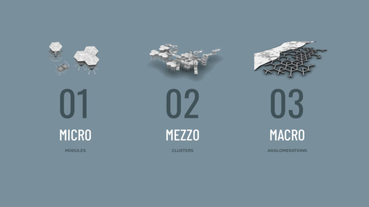
in order to create an overall resilient structure, our team has investigated the studios topic on micro, mezzo and macro scale. all investigations have been carried out in rhino, karamba for grasshopper.
MICRO //
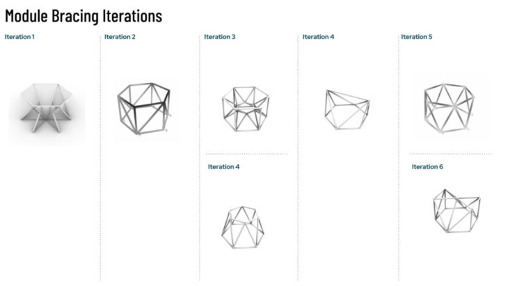
investigating on the fittest single units and small scale proof of concept that connecting the units horizontal and vertically will strengthen the structure overall.
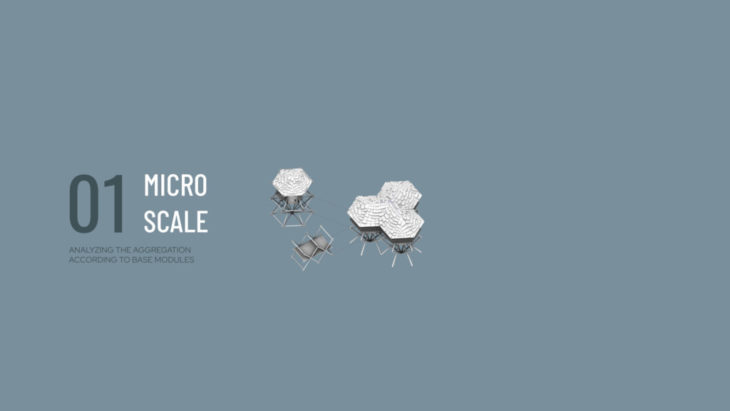
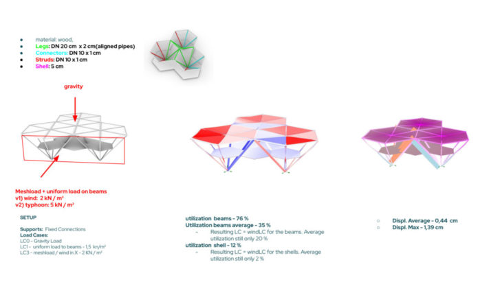
at the micro level, the team has analyzed the strength of individual modules (based from the hexagonal prism) and studied what would be the best framing distribution for the given geometry.
SETUP:
SUPPORTS :Pin Connected
LOAD CASE 0 :Gravity (Dead Load)
LOAD CASE 1 :1,5 kN Uniform Traffic Load
LOAD CASE 2 : 2 kN Mesh / Wind Load
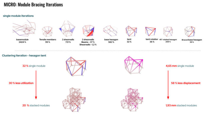
conclusion micro: through this process we were able to proof different module types to be way more stable and therfore more typhoon resilient as a standalone. arraying them vertically and horizontally decreased the general (not average) utilization by 30 % and the displacements by 58 %. therefore we started to take our basemodule and the fittest champion to the mezzo scale for further testings.
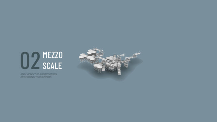
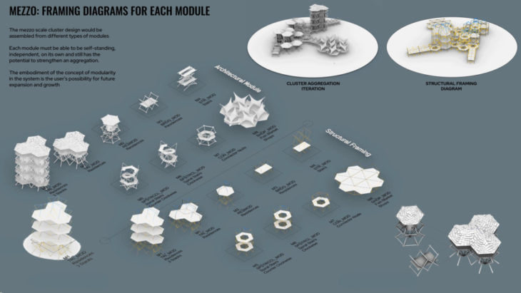
MEZZO//
Investigation on vertical scalability of the different modules will hope to achieve the flexibility to construct at different stages of the building life cycle and would allow the possibility for user assembly and growth.
abstraction of our different module typologies for karamba.
SETUP:
SUPPORTS :Pin Connected
LOAD CASE 0 :Gravity (Dead Load)+
2kN Mesh Const Live Load
LOAD CASE 1 :1kN Roof Beam uniform line
LOAD CASE 2 :2kN Wind Load
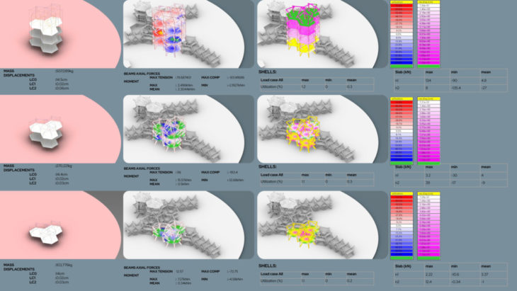
- It was observed that the higher the stacking gets, the higher the axial forces that are applied to the structure
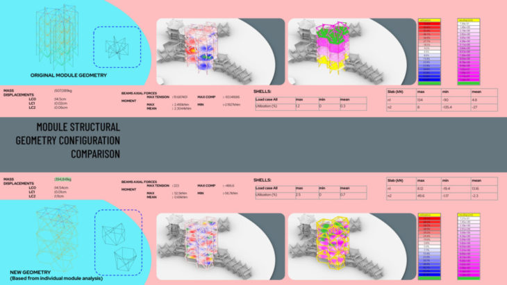
conclusion mezzo – module structural geometry configuration comparison: The new geometry uses lesser material hence the 20% reduction in mass. For the new geometry, there was a significant increase in axial loads and moments but this is due to the material reduction and lesser members to distribute the forces to. The moment mean (for the new geometry) also remains evenly spaced between both max and min thresholds indicating balanced moment distribution unlike the original geometry
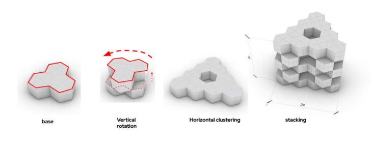
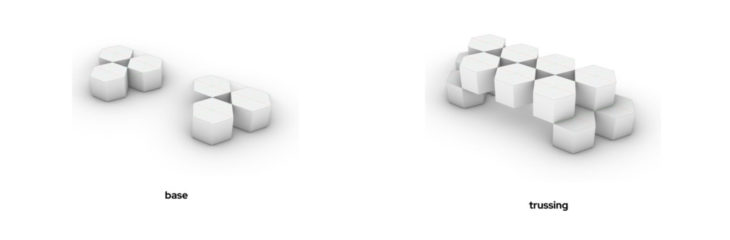
MEZZO – MACRO // cluster iterations
investigating the benefits of bigger clusters and urban patterns. this enabled us to identify stronger + weaker clusters by testing differnt multidirectional truss structures within it.Investigation:
create a strong infill for the urban “strong belt “ structure by identifying truss effects in urban patterns + basemodules,
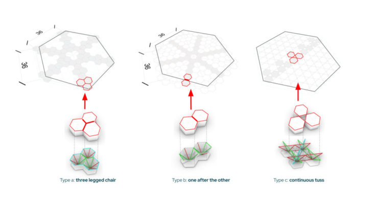
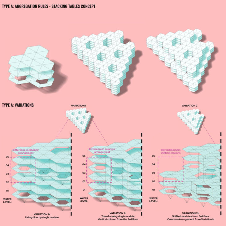
Type A: three legged chair – tripple module – 5 x 4 m building //
Type A: Stacking boxes: 24 x 24 x 20 m //
Stacking – Rotation so the strongest nodes meet.
Horizontal – Building clusters to enable connection of modules
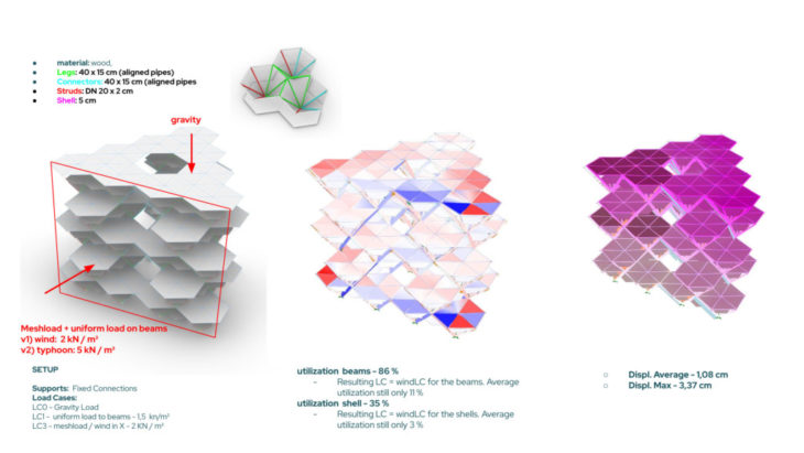
conclusions – Type A: stacking boxes – 24 x 24 x 20 m: Increasing the crosssectoins of the legs (3 dimensional truss) enabled higher staking increase the strength tremendously. Ie.: Until 3 levels – DN 30 cm x 2 cm, Above 3 levels: 40 x 15 cm , legs as steel pipes would be a more efficient approach, simply to use scaffolding pipes. 10 x 2 cm
Connectivity: ( refere to connectors) Once the 5 level structures (3 next to each other) started connecting to each other the overall strength increased again. Therefore the connectors become a higher relevance. Increasing the cross section to = as “strong truss”, max. displacements dropped from 5 cm to 3 cm , Average displacements dropped from 1,6 to 1,16 cm (which is 27 %) Utilization to 102 % to 86 % grid,
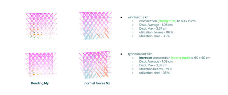
Typhoon: Increased windlaod to 5 kN / m² showed that only increasing the “strong truss” helped the structure to sustain. 40 x 15cm – Utilization: 189 %., 60 x 40 cm – utilization: 79 %
Overall through the stacked stools approach we ve been able to proof, 3d truss takes most of the load + enables the structure to grow more than 5 levels. Connectivity of the elements strengthens the system. Mass 112 t, Average displacements – 1,12 cm, max. 3,37 cm, Recommandation would be to use simple steel pipes ( DN 20 x 1 cm) for the “strong” legs, in order to create a slim and resilient structure. Adding further clusters to the structure would help to strengthen the overall structure further, therefore our assumption “better together in a lattice” can be proven right. The badjao dwelling should be able to sustain the strongest typhoon so far (under the given assumptions – loadcases)
Stacking boxes: 48 x 48 x 24 m //
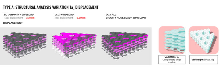
From the displacement diagrams we can understand that the structure is having a big displacement from the 3rd till the 5th level. The reason why this happens is the arrangement of the columns. We see that the diagonal columns are not ideal in the middle of the structure, that’s the reason why we will exchange them with vertical columns. However we will keep the diagonal columns at the basement, since the work pretty well.
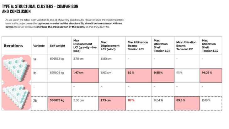
TYPE A: Stacking boxes: 48 x 48 x 24 m – comparison and conclusions //
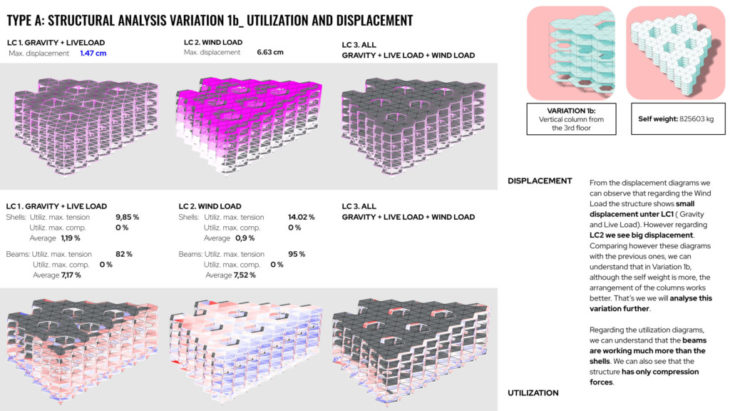
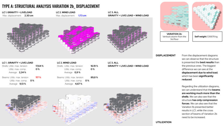
As we see in the table, both Variation 1b and 2b show very good results. However since the most important issue in this project were the typhoons we selected the structure 2b, since it behaves almost 4 times better. However we have to increase the cross section of the beams, so that they don’t fail.
TYPE B: RATIO TESTS
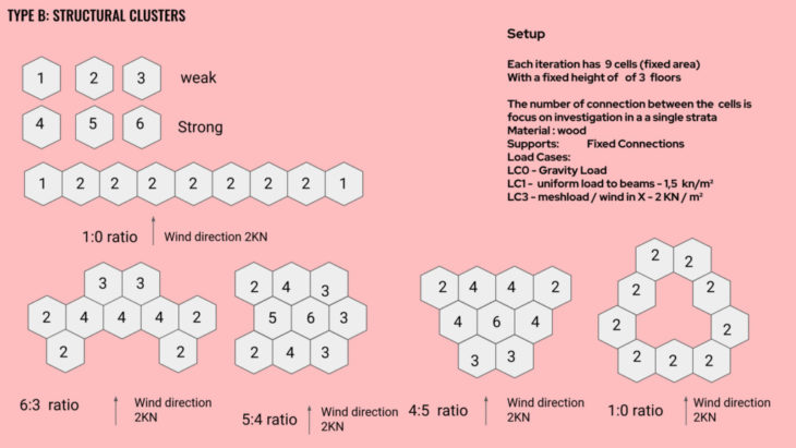
Setup: Each iteration has 9 cells (fixed area) with a fixed height of of 3 floors. the number of connection between the cells is focus on investigation in a a single strata
Material : wood
Supports: Fixed Connections
Load Cases:
LC0 – Gravity Load
LC1 – uniform load to beams – 1,5 kn/m²
LC3 – meshload / wind in X – 2 KN / m²
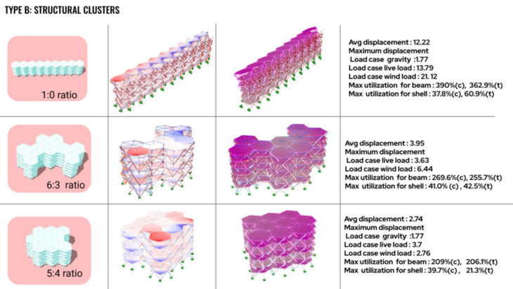
ratio 1:0: This iteration was showed the need to deepen the lattice. Just the cell attachment on either side doesnt allow for even distribution of force and we are unable to maximize the geometric potential that hexagonal shape offers. The structure suffers from bending . the higher unitization is on the weaker connection that can be reduced but increasing the section. Low number of connections = weaker the performance.
ratio 6:3: The lattice was broken into 3 clusters of cells then joined. The structure performs better the cluster 0 reducing the utilization by approx 100% and avg displacement is reduced tremendously/ However the angular joins as show in the diagram experience the highest loads . The center of the cluster experience the least amount of stress . which means if the cluster is extended the max utilization would decrease
ratio 4:5: The lattice is arranged in 3 layers of cells this arrangement has shown almost 200% decrease in max utilization from cluster 0 . The cluster’s over all stress as seen in the diagrams show that the max utilization is on certain isolated parts . the layer that directly experience the wind load has shown an increase in stress. Wind facing diagonals experience tensile forces while cells on the oposite side experience the compressive force.
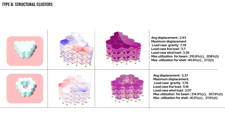
ratio 1:0: The lattice is arranged in 3 layers of cells forming a triangular form .This arrangement has shown almost 200% decrease in max utilization from cluster 0. The converging edge of the lattice is its weakest part of the arrangement Because of the arrangement one side of the triangle experiences the tensile force while the opposite side is in compression .
ratio 5:4: The lattice is arranged in 3 layers of cells forming a triangular form . but with having the center cells . this reduces the internal links and reduces the performance of the cluster. The tensile utilization of its beams is the same as cluster 0 . this shows the importance of the interconnection of the lattice if we want improve the strength
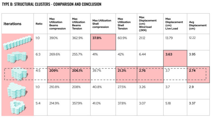
TYPE B: ratio tests – comparison and conclusions //
the number of interconnection with in the lattice is correlated to an increase in lattice strength as show in 4:5 ratio. the location of punctures within the lattice have an impact on its optimization and relates to the breakdown of lattice interconnectivity . over all geometric form has an impact on the optimization. if a form had to many edges it resulted in decrease in the performance of the structure.
TYPE C: continuous truss
investigation: continuous truss through three hexagons shifted, Stability 4 m truss effect within the structure, Connectivity of subtrusses, Create stable footpoint, Use trussing effect on the badjao cluster, possible use cases is stacked housing or boat bridge.
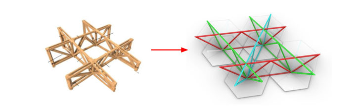
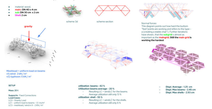
TYPE C: continuous truss – comparison and conclusions //
the analysis points out how hard the buttom “feet”points are working (refer to normal forces diagram) and refers to the type – a (creating a stable chair”). Further iterations have shown, that the subgridi is almost as important as the maingrid. Still the main grid (red) is working the hardest. through type c approach the community would be enabled to create bridge cantilevering and stacked multiuse (i.e..: housing) structures. average displacments are below the acceptable ratio for a 21 m spanning bridge (21.000 / 400 = 52 mm max. acceptable ratio). utilization ratios are in an acceptable range, but average ratio points out, that the truss above is still working to less, therefore further optimizations would be the next step here .
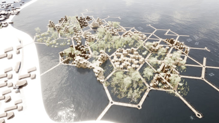
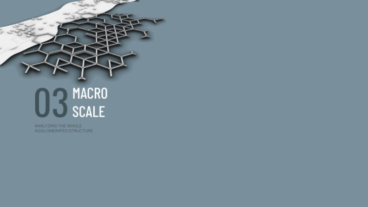
MACRO //
investigating the urban scale of the lattice, strenghts and weaknesses within the natural growth of the community. and possible ways to sheperd the growth into a strong + interconnected urban structure.the goal was to identify the strongest truss structure type that will create some kind of safe belt – sacrificial layer within our urban lattice.
site settings:

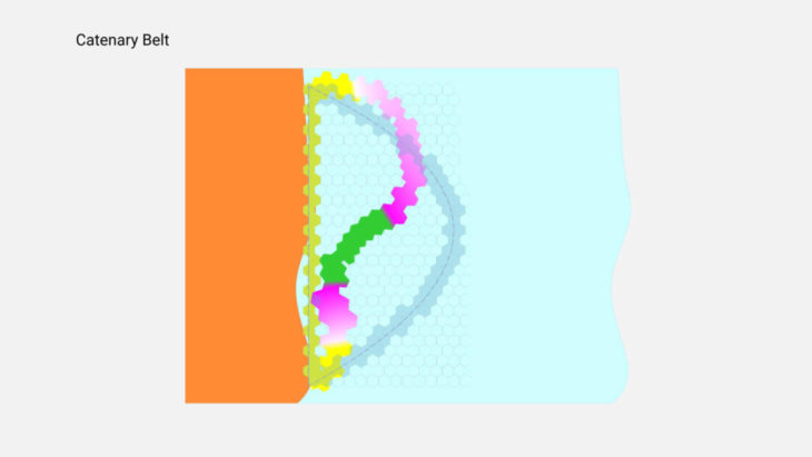
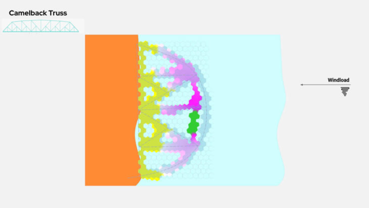
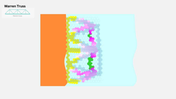
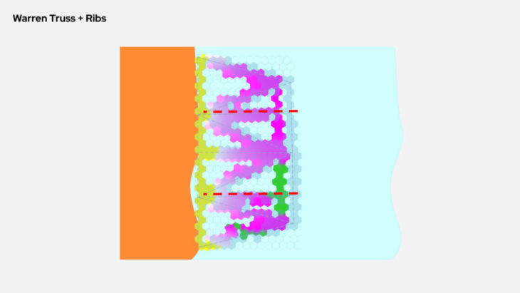
macro concusion //
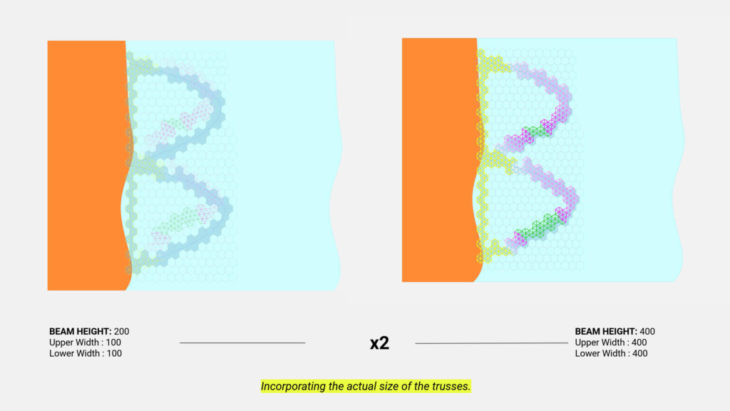
in order to understand the behaviour of the hexagonal gridsystem better, the truss was on purpose dimensioned as wooden material 200 x 200 cm (weaker than the actual structure) rectangular cross section. where needed the hexagonal shape was triangulated as much as required. this has led the investigations through different truss shapes. not suprisingly the truss with the most bracings (refer to warren truss with ribs) performed the best. the belt structures behaved like a catenary structure, increasing the height + decreasing the depth of the parable belt has led to a sufficient result as well. once the structure was increased to the actual size of the trussings 600 x 400 cm – refer mezz/macro – type A + C, more or less all truss types + parabloid types performed well in therms of displacements. this proofs that the subtrusses of the overall grid will stiffen the structure sufficiently to prevent it in case of a typhoon from colapsing (under the assumed loadcases).
credits
BADJAO, thyphoon resilient structures for the philippines is a project of IAAC, Institute for Advanced Architecture of Catalonia developed at Master in Advanced Computation for Architecture and Design (MaCAD) in 2021/22 by students Neil John Bersabe, Maria Papadimitraki, Mahmoud Ramdane, Clemens Russ, Daniyal Tariq and Faculty zen master Manja van de Worp and Matthew Gabe