The Hive // Wolfgang Buttress [@ the Royal Botanical Gardens at Kew, in London]
” I’m not an architect, I’m an artist, so I was more interested in the experience and in how you could convey an idea and a feeling through an experience rather than an object or a building ” –– Wolfgang Buttress
The Hive consists of 32 horizontal stacked layers of hexagonal geometry creating an abstracted analogue of a honeycomb. A rotational twist in the aluminium structure introduces movement, suggestive of a swarm. The form is a 17 m cube raised-up on columns, appearing almost to hover, a spherical void hollowed from the centre, allows visitors to enter. Walking beneath the sculpture, visitors may peer up through the glass floor into the interior. The Hive’s distinctive mesh frame is constructed from 170,000 aluminium parts and 1,000 LED lights.
Fabrication Strategy+diagrams
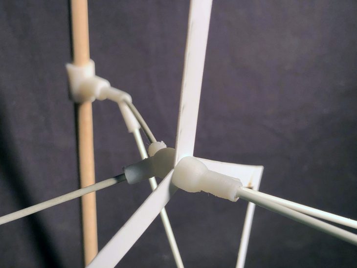
The objective behind the fabrication strategy consisted of creating a sectional model by taking a macro zoomed portion of the pavilion and deconstruct it to understand the nodes & connections established. The prototype inspired by The Hive // Wolfgang Buttress focused on understanding the nodes & connections found in the structure. We directed our designs based on Snap Fastener techniques. A snap fastener is a pair of interlocking discs: a circular lip under one disc fits into a groove on the top of the other. A connection catalogue was later designed & developed according to our findings.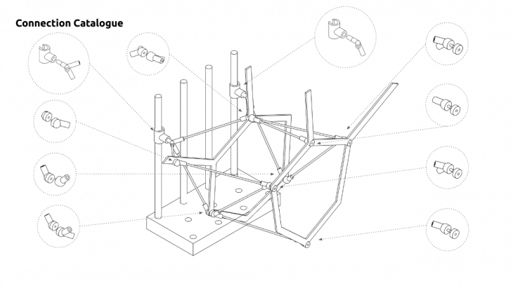
Find below an exploded axonometric view showing the different layers of the sectional model & the slicing settings used for fabrication including the machine, software, print time & material quantity.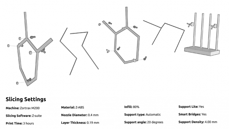
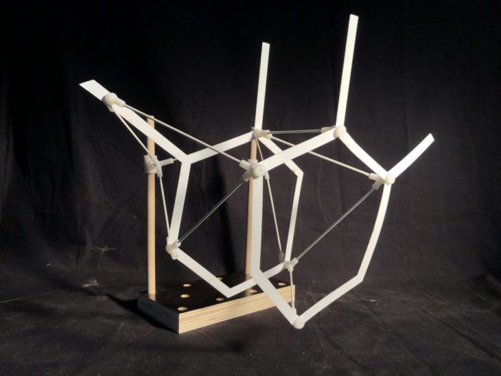
Fabrication Final Outcome
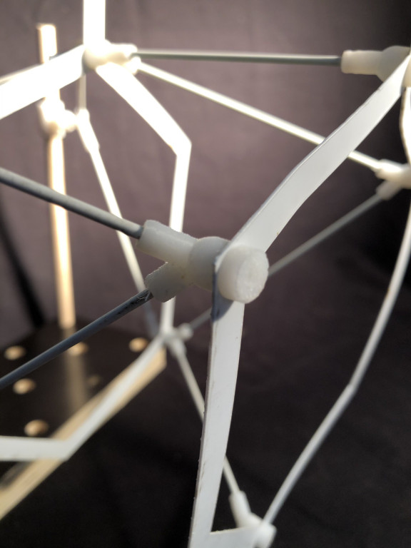
Find below pictures of the final outcome.