The ‘Developable Strips’ workshop covered the entire process from design and analysis through digital fabrication to assembly and completion.
The digital fabrication was done in two main steps: initial CNC milling to prepare flat strips and then robotic bending to get the set of bent strips from which the final lighting appliance was assembled. This post explains the initial CNC milling.
The workshop was conceived from the start to have as an input for the robotic bending a series of aluminium strips of a specific size: 933mm long, 60mm wide and 1mm thick. A pick-up jig was designed and made beside the robot specifically to be able to deal with this size of part. The CNC milling included cutting the profile of these straight strips, but more importantly it also included milling a number of ?1.5mm holes along the length of a set of crease lines placed along the length of the part.
The definition of these crease lines – their position along the strip and the angle at which they cross the strip – was derived from the previous design and analysis steps. In designer-talk, the crease lines are the main output from the design phase to the fabrication phase after ‘design freeze’. The position of the crease lines along the strip and the angle at which they cross the strip encapsulate the way the flat strips will be transformed into curved strips by the robotic bending process, which references the crease lines prepared in the CNC milling step and adds the correct angle of bending at each crease line to complete the digital fabrication of the parts.
The image below shows a set of 19 crease lines crossing one of the flat aluminium strips that were CNC milled. The red text (angles in degrees) on each crease line is the bend angle to be applied in the robotic bending stage of fabrication, and the black text (also angles in degrees) is the amount the crease line is leaning away from being normal to the long edges of the strip i.e. the angle relative to either end of the strip.
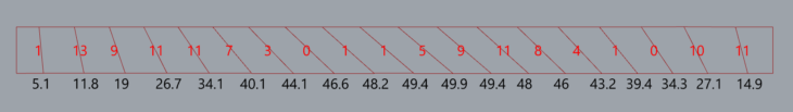
As mentioned above, each crease line has a series of ?1.5mm through holes drilled along its length. The purpose of this string of holes is to make the bending process easier: by weakening the aluminium in exactly the places we plan to bend it, the bending can happen more easily.
Each group derived their set of crease lines from their developable strip prepared in Rhino/Grasshopper/Kangaroo, after which a script was used to apply the series of holes to the crease lines.
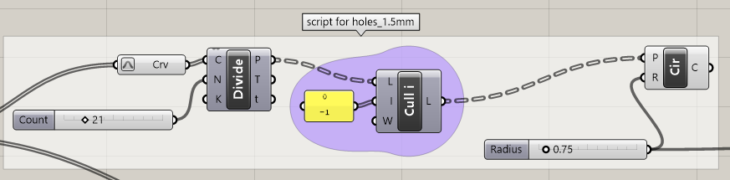
This script sets a number of holes and spaces them evenly along the crease lines. When the angle of the crease lines is relatively low, for example towards the ends of the strip shown above, then the amount of aluminium that remains along the crease lines after the holes are cut does not vary too much, and so the lines should present a similar amount of resistance to bending. For example, placing 20 holes of ?1.5mm removes 30mm of material, or 50% of the 60mm wide strip in the case of a line straight across the strip. But when the angle of the crease line is greater, for example towards the middle of the strip shown above, then an alternative script which takes into account the length of the crease lines and adjusts the number of holes made accordingly to leave a similar amount of aluminium on every crease line may be more appropriate. A script like that is shown below.

This alternative script can be set to maintain a near-constant quantity of aluminium remaining along the crease lines, no matter what their length, and may help improve the results of the folding process for strips with higher crease line angles. Note that the strip used as an example had by far the highest crease line angles of all the strips prepared by CNC milling, and may be the only one that might have benefitted significantly from this alternative script.
Once the crease line holes had been defined for each strip, they were imported into a set-up in RhinoCAM to mill a full set of 8 strips on the 3-axis milling machine. The milling process had 4 operations:
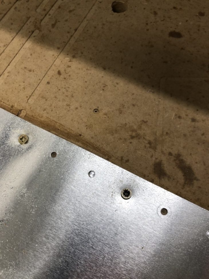
1 Workpiece Hold-Down: A series of ?4mm holes outside the profiles of the strips were drilled to hold down the sheet. These holes are where the screws are in the image below.
2 Strip Ends Hold-Down: A pair ?4mm holes close to each end of each of the strips were added to hold down the ends of the strips, even after the profile milling was completed. These are the holes which have not yet got screws in them in the image below.
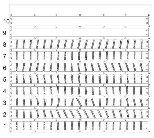
3 Crease Lines Holes : The strings of ?1.5mm holes along each crease line. The overall view for a full set of sheets can be seen in the image below. The image is of the second set of strips, so does not contain the example strip from above with the steeper crease line angles – in this set you can appreciate that most crease line angles were quite low.
The time-lapse video below shows some of the crease line holes being drilled.
4 Strip Profiling: CNC milling the full outlines of the parts. The image below shows the result after the 4 operations.
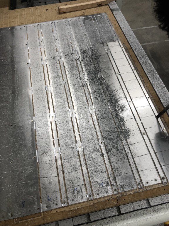
As is evident from the image above, to complete the process, a number of manual post-processing tasks had to be done before the strips were ready to be presented in the jig for the robotic bending process. Cleaning the parts and releasing them from the sheet was the first manual process. Cleaning was required because the sheet of aluminium had a thin layer of cutting oil applied to it, to help the cutters enter the material. The swarf from the hole drilling and the profile milling stuck to the cutting oil, and both needed to be cleaned from the sheet before the strips could be removed.
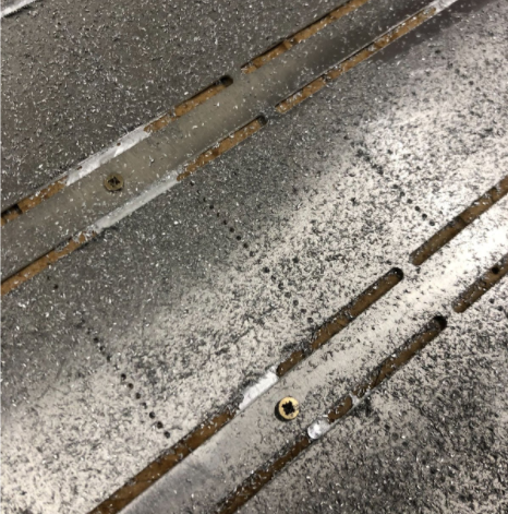
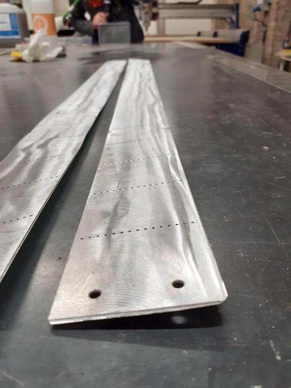
Releasing the strips was not simple. The profiling operation had purposefully left some parts of the outline uncut. This is a normal safety measure to prevent parts from moving or flying away when they become completely free of the sheet they are cut from. These ‘bridges’ or ‘tabs’ are the full thickness of the material, 1mm. Also there were areas where the profiling operation had been supposed to cut through the material, but had not managed to do so. This was always close to hold-down screws and occurs because that part of the sheet material has been held down further – further down than the depth of the milling operation! This problem can be seen in the image below, by the screws.
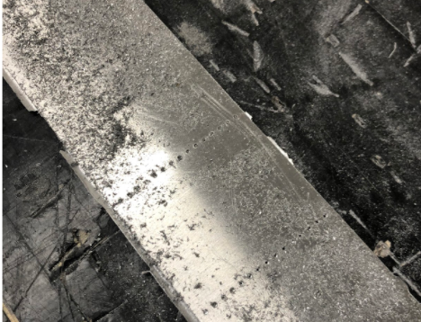
Once the strips were freed from the sheet they had significant imperfections or ‘burrs’ of material along the profile edges – shown in the image below.
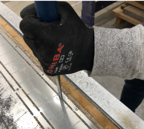
The easiest way to clean up the profile edges was using a band sander, shown below. Each group took responsibility for manually finishing their own strip.
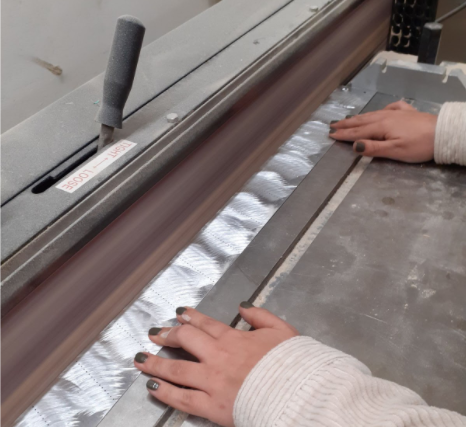
The drilled holes also had burrs, and they also needed to be sanded to remove them. Also a ‘brushed’ style finish was applied to all the strips to make them similar in appearance – it would not have been practical to keep or to recover a shiny, near mirror-like finish to the aluminium after the CNC milling and the deburring, etc.
After cleaning, removing from the CNC bed, deburring the holes and the whole profile, and manually adding the ‘brushed’ finish, the strips ended up as shown above. Like this they were ready to be the ‘input’ for the more important of the two digital fabrication processes, the robotic bending.
‘Workshop 1.2 : Developable Strips – Flat Strips CNC Milling’ is a project of IAAC, Institute for Advanced Architecture of Catalonia developed at the Master of Robotics and Advanced Construction in 2021-2022 by:
Students: Christopher Booth and Tomás Quijano
Faculty: Efilena Baseta and Marielena Papandreou
