URBAN WIND TOWERS
Passive Cooling Systems in Urban Heat Islands
Abstract
Majority of the future population is expected to be living in urban areas which makes high-density housing (existing and future) a critical building typology. These typologies are most difficult for future interventions and even demolition due to presence of multiple shareholders. Due to urban-heat-island-effect cooling loads within the urban buildings have been rising and reliance on H.V.A.C. systems have risen. Adapting existing and future buildings through incorporation of passive cooling systems can reduce the energy demand. Case-study of Residential apartment building in La Rambla, Barcelona was conducted to study how incorporating wind towers into shafts existing within these building typologies can improve wind circulation. CFD analysis was done using Simscale (browser-based CFD platform) to study air flow patterns of proposed interventions and modifications were analyzed to improve wind distribution, speed and reduce turbulence. Natural phenomena including stack effect and venturi effect were used to streamline the wind flow. Smoke simulations of Houdini software were used to design the elements of Wind catcher inlet to increase the catchment capacity. Using the results a passive cooling system was proposed. Using this system, spatial distribution of buildings were analyzed and a proposal for redesign of apartments was suggested. Future studies are required to analyze how existing buildings typology can be retrofitted through studying their existing spatial distribution and shaft location to propose wind tower incorporation. Through Energy analysis and using Adaptive comfort calculators, parameters of passive cooling systems can be optimized to provide required air-circulation rates within modern urban buildings.
Keywords: Passive cooling systems, Computational Fluid Dynamics Analysis, Environmental and Regenerative Design, Urban Building typology, Sustainability
-
INTRODUCTION
By 2050 the world’s population is expected to increase up to 9.7 billion people, 68% of which will be living in urban areas. Future construction has potential of increasing the global C02 emissions from construction industry to more than the current 40% contribution(“The World’s Cities in 2018” n.d.)?. Cooling in buildings accounts for 10% of energy consumption worldwide, a number which is subject to increase with rise in global warming. As of 2016, residential sectors across various countries have been more reliant on Air- conditioning in comparison to commercial buildings ( Table 1)(- International Energy Agency n.d.) .
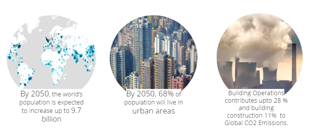 Table 1: Air-conditioning units and cooling capacity by country/region, 2016
| Installed stock | Annual sales | |||||||||||
| Million units | Gigawatt output capacity | Million units | Gigawatt output capacity | |||||||||
| Res | Com | Total | Res | Com | Total | Res | Com | Total | Res | Com | Total | |
| United States | 241 | 132 | 374 | 2295 | 2430 | 4726 | 16 | 8 | 24 | 314 | 129 | 443 |
| European Union | 43 | 53 | 97 | 192 | 654 | 847 | 9 | 3 | 12 | 34 | 41 | 75 |
| Japan | 116 | 33 | 148 | 407 | 352 | 759 | 9 | 2 | 11 | 47 | 14 | 61 |
| Korea | 30 | 28 | 59 | 129 | 220 | 348 | 2 | 2 | 4 | 19 | 15 | 34 |
| Mexico | 7 | 9 | 16 | 40 | 65 | 105 | 1 | 1 | 2 | 5 | 6 | 10 |
| China | 432 | 138 | 569 | 2092 | 807 | 2899 | 41 | 12 | 53 | 305 | 81 | 386 |
| India | 14 | 13 | 27 | 77 | 72 | 149 | 3 | 2 | 4 | 14 | 12 | 25 |
| Indonesia | 7 | 5 | 12 | 32 | 27 | 59 | 1 | 1 | 2 | 5 | 4 | 9 |
| Brazil | 14 | 14 | 27 | 59 | 68 | 127 | 1 | 0.3 | 1 | 5 | 1.4 | 6 |
| South Africa | 1 | 1 | 3 | 6 | 15 | 22 | 0.1 | 0.1 | 0.3 | 0.9 | 1.1 | 2.1 |
| Middle East | 30 | 18 | 47 | 147 | 153 | 299 | 4 | 2 | 6 | 29 | 16 | 45 |
| World | 1093 | 529 | 1622 | 6181 | 5491 | 11673 | 94 | 40 | 135 | 848 | 359 | 1207 |
Existing Urban housing lacks the flexibility of design and structural intervention, once construction is done which makes users dependent on constant use of H.V.A.C. (Heating, Ventilation and Air conditioning) systems permanently. These buildings are most difficult to renovate or demolish because of multiple shareholders involved, which makes these constructions more permanent and a constant contributor to Urban Heat Island Effect. Urban Heat Island effect due to replacement of natural land cover with pavements, buildings and other surfaces which absorb and retain heat for longer duration have led to increased energy cost for air conditioning, heat related illness and higher mortality rates (US EPA, n.d.).
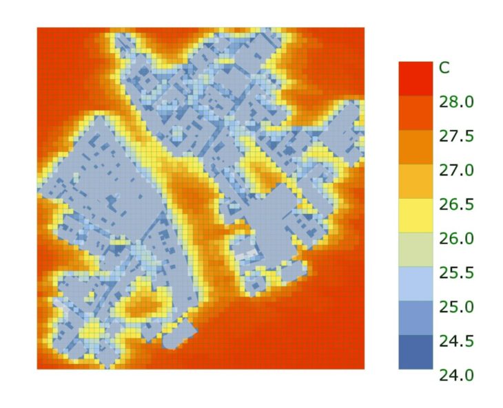
Thermal Comfort is defined as comfortable conditions mentally and physiologically to perform to its capacity comfortably. Factors including metabolic rate, clothing insulation, air temperature, mean radiant temperature, air speed and relative humidity influences the thermal comfort (“Standard 55 – Thermal Environmental Conditions for Human Occupancy” n.d.). U.T.C.I. – Universal thermal comfort index which is an equivalent temperature (°C), it is a measure of the human physiological response to the thermal environment, was used to do micro-climate analysis of La Rambla area by using U.T.C.I. calculator of Ladybug tools to understand the increase of ambient temperature due to Heat Island Effect. Average dry bulb temperature for selected period being approximately 25 °C (Figure 1)(Mostapha Sadeghipour Roudsari 2020).
1.1. PASSIVE COOLING TECHNIQUES.
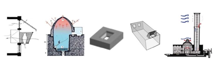
Passive cooling systems have been part of traditional architecture of ancient Egypt and subsequently spread to the Middle East, to north India, to north Africa and to southern Spain. Recently these traditions have been revived in works of Hasan Fathy and other architects (Ford and Ford 2002). Techniques like Mashrabiya, Yakhchal, Courtyard design, Malqaf and Wind towers (Figure 2) have been used for centuries for providing thermally comfortable living spaces in hot and dry climate through passive means.
Modern Urban Building forms are mostly designed from the perspective of space efficiency stand point which have progressively faded out these passive cooling systems from their incorporation. These systems can now be considered redundant spaces but they did serve one of the key functions of any shelter that being of providing thermally comfortable living space. Though function is now being served through the incorporation of H.V.A.C. systems but is very energy extensive.
1.3 CASE- STUDY – 31, LA RAMBLA DEL CAPUTXINS, BARCELONA, SPAIN
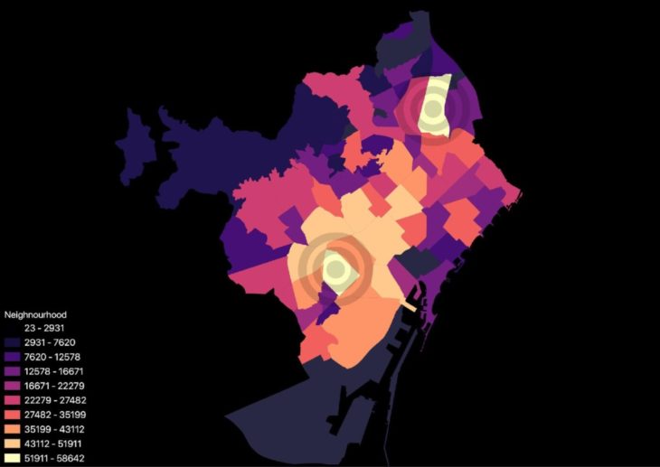
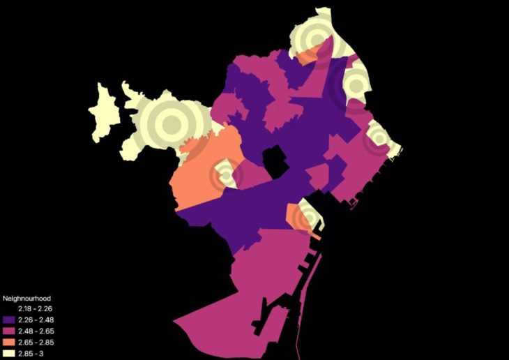
The research is developed through conducting a case study of a residential apartment buildings located in La Rambla, Barcelona area at 31, La Rambla del Caputxins. An apartment building in La Rambla area was selected because of high number of residential apartments (Figure 4) as well as higher numbers of resident population in Barcelona (Figure 3) (“Addresses According to the Population Register” n.d.).

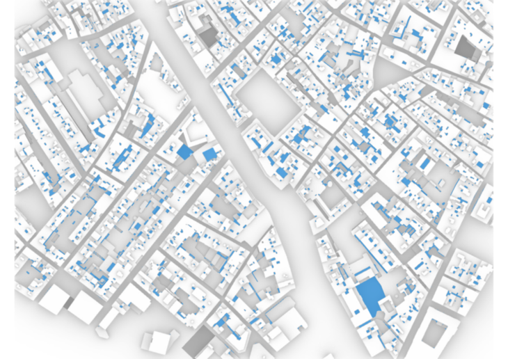
The urban landscape of La Rambla area has similar characteristics to various densely-packed urban areas which are in form of row-housing. Cooling loads in these types of dwellings are usually accounted for because of lack of natural ventilation and various other factors. Availability of shafts for day-lighting purposes and ventilation purposes in these housing also resembles the building typology of the majority of high-density housing (Figure 5).
</p>
Based on the existing typology of urban areas like around La Ramblas which is highly densely populated row housing with presence of shafts, out of the various passive cooling techniques, Wind Towers and Mashrabiya were selected to be most suitable for designing a possible intervention in existing buildings and being possible design driver for future urban buildings. Wind Towers designed by modification of shafts is a macro level intervention which performs by altering the form of the building, whereas modern day mashrabiya like Cool Spot (Figure 7)(“Cold Spot: Evaporative Cooling through Ceramics – Climate CoLab” n.d.) and Cool brick Figure 6 (“Cool Brick | Emerging Objects” n.d.) are micro level intervention focused on Facade design.
This research paper explores the Macro level intervention of incorporation of wind towers within building design. Due to the availability of shafts in these typology wind towers were selected as a passive cooling systems which could facilitate passive cooling phenomenons use of energy dependent cooling systems can be reduced.
- STATE OF THE ART
- MASDAR CITY WIND TOWER –
The Masdar City Wind Tower is a contemporary interpretation of the traditional Arabic wind tower, or barjeel (Figure 8). At a height of 45 meters, the tower captures cooler upper-level winds and directs them to the public square at its base. Sensors at the top of the steel structure operate louvers to open in the direction of prevailing winds so as to divert wind down the tower(“Sustainability – Sustainable Urban Development – Masdar City” n.d.). Also the tower is capable of provoking a convection current as hot air rises simply through passage through the cross-section(“Masdar City’s Wind Tower: Literally Cool” n.d.).
- TORRENT RESEARCH CENTER, AHMEDABAD –
Built on the principle of Passive Downdraught Evaporative Cooling, this research center was designed by Abhikram Architects in 1998 (Figure 9). Measurements of air temperature and relative humidity in different parts of the building in April 1998 revealed that very significant cooling and high air change rates were achieved. Peak temperatures of 27°C in the ground floor laboratory, and 29°C at first floor, were achieved when the external maximum reached 38°C. Over the same period, air change rates of 9 per hour on the ground floor and 6 per hour at first floor were recorded. The staff reported that during the summer (February – June) the laboratories are comfortable without fans and are not stuffy or smelly, as most chemistry labs are, even when air conditioned. During the monsoon (July – September), the evaporative cooling system is not operated, of course, so ceiling fans are used to enhance comfort for these two to three months. In the first year since its occupation, the Torrent Research Center was reported to have used approximately 64% less electrical energy than the equivalent conventionally air-conditioned building. Expenditure on M&E plant was reduced by 36%, which also provides further savings in maintenance costs (Ford and Ford 2002). 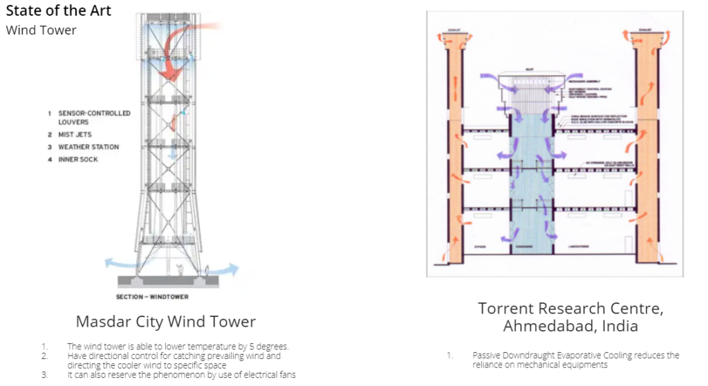
- METHODS
The shafts been identified as building elements which can be configured for passive cooling, an existing building located at 31 La Rambla del Caputxins was selected and shaft sizes were taken to analyze the performance of the interventions (Figure 10) . Blue colored zones indicating the shafts.
3.1 PROPOSED PASSIVE COOLING SYSTEM – URBAN WIND TOWERS
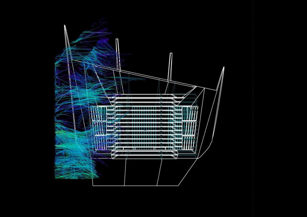
The proposed passive cooling system consists of designing of three elements namely, Outside Air Inlet, Shaft and Inside Air Outlet. These elements were designed through conducting Computational Fluid Dynamics (C.F.D.) analysis on the form through Simscale – a browser based C.F.D. simulation platform (SimScale GmbH, Munich 2021) .
3.1.1. SHAFT DESIGN – Existing shaft of dimensions 3m by 7m was selected and following interventions were analyzed.
CASE 1. EXISTING SHAFT CONFIGURED WITH A WIND CATCHER INLET.
C.F.D. analysis was performed on two scenarios with a building model with wind catcher designed at the shaft opening (Figure 12).
1.A. Window sizes were kept the same on all floor levels.
1.B. Window sizes were decreasing with increasing floor levels.
In the case 1.A wind distribution is more consistent in upper floors than lower floors. In the case 1.B with larger window dimensions at lower levels and smaller window sizes at higher levels, better wind distribution was observed at lower levels. Due to smaller window cross-section at higher levels more volume of air were allowed to flow to lower levels increasing the ventilation rate in the spaces adjacent to the shaft.
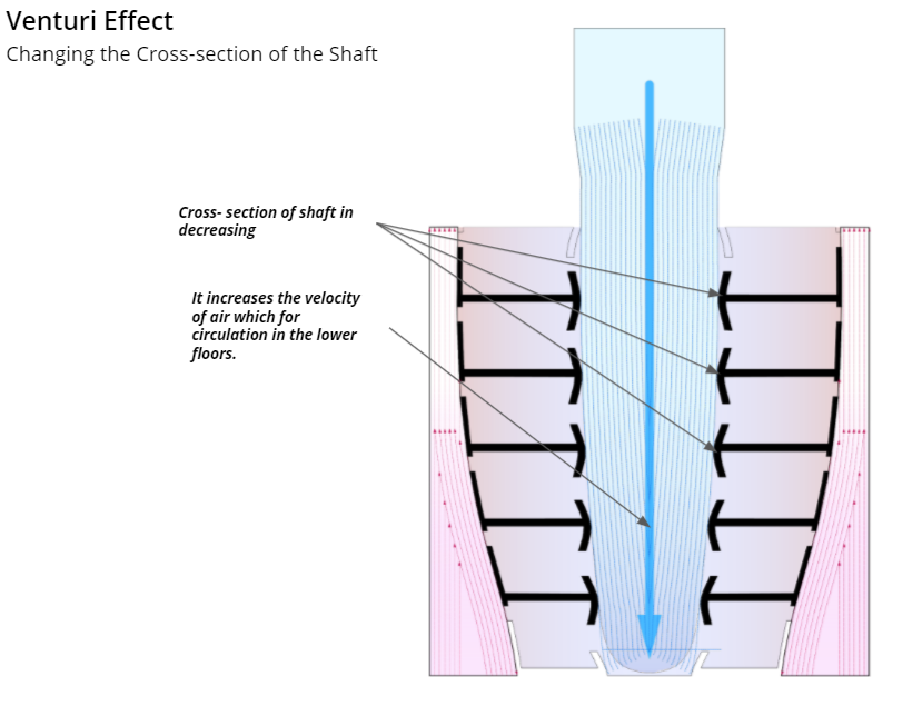
CASE 2. SHAFT CROSS-SECTION AREA INCREASES WITH FLOOR LEVELS.
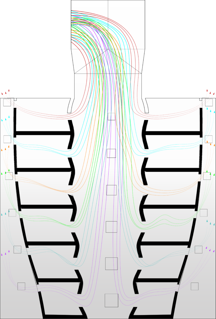
Cross sectional area of the shaft at floor levels was reconfigured to increase with height of the shaft to use Venturi effect(Reader-Harris 2015) to speed up the air velocity within the shaft as its directed downwards (Figure 13).
CFD analysis was done with a cross-sectional area of the wind tower configured in two scenarios. Case 2.A with the window sizes kept uniform throughout all the floors and Case 2.B with window sizes decreases with increase in floor level.
In the Case 2.A, in comparison to the previous Case 1.A where the shaft cross-sectional area was not altered, wind distribution was found to be more streamlined and less dead zones were observed.
In the Case 2.B, with window sizes decreasing as level is increasing, better wind distribution was observed for lower levels.
CASE 3. SHAFT CROSS-SECTION INCREASES WITH LEVELS AND HOT AIR EXHAUST.
Case 2.A and Case 2.B was modified with the addition of a hot air exhaust shaft with an opening designed on the wall opposite to the wind tower shaft wall. Stack effect in the living spaces lead the hot air generated within the space to escape to the hot air shaft (Figure 15). The system created an improved streamline distribution and reduced the mixing of hot air within the living spaces with the air from the wind tower shaft. It also reduced the turbulence within the space, created a cross-ventilation system which led to improved wind speeds and steady flow.
CFD analysis was done in two scenarios with this system. Case 3.A with window sizes kept same through all floor levels. Case 3.B with window sizes decreasing with increasing floor levels.
In Case 3.A wind flow was found to be more streamlined and consistent with less turbulence than the previous system without the hot air exhaust shaft. Wind flow was observed to pass through habitable elevations within the living spaces due the presence of the exhaust at a high level of the wall of hot- air shaft.
In Case 3.B, as in previous cases, wind flow in the lower levels was observed to improve than the Case 2.A and Case 2.B. Wind speed through the spaces was also observed to be increased.
CASE 4. THREE-SIDED SHAFT WITH CROSS-SECTION AREA INCREASING WITH LEVELS AND HOT AIR EXHAUST.
In this system living spaces were removed from one side of the shaft in case to allow sunlight enter these shafts using a transparent material to allow the daylight into the shaft cross-section. The system was analyzed in two scenarios. The Case 4.A with window sizes remaining the same through all floor levels and Case 4.B with window sizes decreasing with increasing floor levels (Figure 17).
In comparison of Case 4.A and Case 4.B, in the Case 4.B wind distribution in lower levels was observed to greatly improve in comparison with the Case 4.A. Less dead zones were also observed in the case 4.B in comparison with the Case 4.A.
The system when optimized with window sizes in relation to cross-sectional area, allows for better air distribution for spaces located at lower levels (Figure 18). Thus increasing the wind velocity through venturi effect towards the lower level with reduced window cross-section at higher levels allows more air volume to flow towards the lower levels (“Continuity Equation” n.d.).
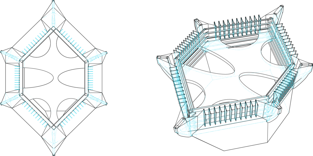
3.1.2. WIND TOWER INLET –
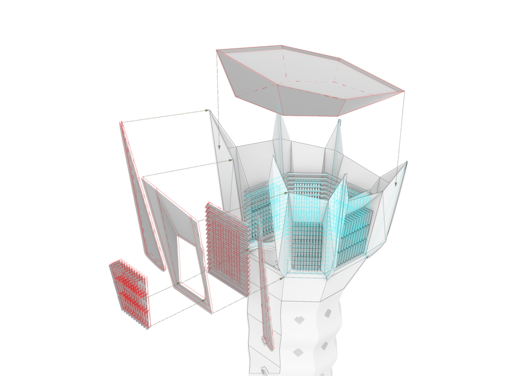
Design of the Wind catcher Inlet was designed to be hexagonal which improves the air catching capacity of the system in comparison to a rectangular shape one. Hexagonal form allowed the wind catcher to direct wind towards the shaft from multiple directions irrespective of the prevailing wind direction which was a drawback in the traditional wind catcher – their lack of changing orientation according to prevailing winds (Figure 19).
As observed in the traditional wind tower design the connection between the wind catcher inlet and shaft was streamlined using a quarter sphere cross-section from all the inlet directions. Horizontal Louvers were designed at the inlet so to control the wind velocity (Figure 20). Larger cross-section can be used during days with lower wind speed and more humid days and smaller cross-section can be used during windy days (Figure 21).
</p>
Vertical Louvers were designed in front of the horizontal louvers to adjust accordingly to the prevailing wind direction. Angled skin detail was added to direct the wind towards the inlet cross-section through the louvers. Vertical Blades which are radially protruding outside which directs the wind towards the angled skin detail when the wind direction is not perpendicular to the inlet. This increased the wind catching ability of the system.
The proposed design increases the wind catching ability of the wind towers in comparison to its traditional counterparts. Hexagonal shape provided multi-directional catchment surfaces along with enough vertical surface from all directions (Figure 23). Directional details like vertical blades, vertical louvers and angled skin detail increases the performance of the system and the quarter sphere section of the inlet provides a streamlined wind flow towards the shaft (Figure 22). The 3d modeling was done in Rhinoceros and Grasshopper software and Smoke simulations were performed using Houdini software.
</p>
3.2. SPATIAL DISTRIBUTION – CONFIGURATIONS
Configuration of proposed system with wind towers and exhaust shafts designed around the living spaces was analyzed to propose a spatial distribution of functions. Three distributions were analyzed in highly dense row housing typology with lack of facades with access to fresh air.
SD1 was designed for a scenario with rectangular shafts with narrow front and back facades. Multiple wind towers were proposed within the space and living spaces were designed around the wind tower shaft. Due the rectangular shape of the shaft, number of living spaces around the tower was found to be a limiting factor. The living spaces were designed to be rectangular as the prevalent observed spaces within residential apartments. This was also found to be a limiting factor because of the lack of flexibility within spaces. Hot air exhausts were designed across the living spaces. Due to the rectangular configuration of spaces hot- air exhaust could not be connected to more than three spaces connected to wind towers which made them space deficient features
SD2 was designed with a multiple- sided wind tower and radial distribution of the spaces around the tower. Increasing the sides of the wind tower increased the number of spaces which could be cooled down by the system. It also gives the possibility to remove living spaces from one direction and use transparent material to allow sunlight to enter the shaft areas. Though this configuration increased the number of spaces which could be cooled passively and by giving the flexibility of space design by moving away from rigid rectangular spaces to distorted spaces also made possible but due to radial distribution of the spaces hot air exhausts cannot be utilized for more than three spaces in most cases. The number of hot air exhausts to be provided was found to be excessive in this case.
In the SD3 a hybrid of the SD1 and SD2 was designed. Spaces were designed organically around multi-sided wind towers and exhaust shafts. Flexible spatial forms of living spaces were explored so as to increase the number of connections between spaces and towers.
In conclusion the SD3 with its flexible spatial forms and multi-sided wind towers reduced the number of both towers and exhaust shafts while maximizing the number of the living spaces which could be cooled (Figure 24). 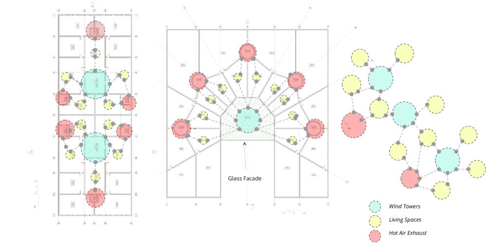
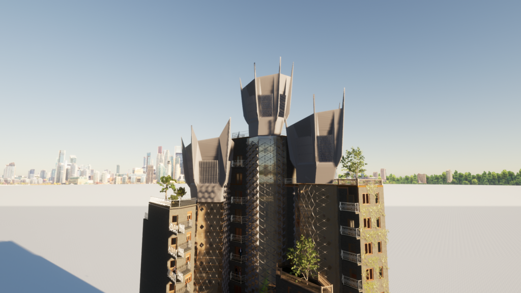
In the proposed redesign of the chosen site of the case- study the chosen system was employed and possible spatial distributions were analyzed. The southern sides of wind towers were made of glass panels with vertical louvers to allow the access of sunlight into the shafts and reduce the radiation levels respectively (Figure 26). Service spaces like Staircases, elevator shafts and lobbies were used as Hot-air exhaust shafts. Their sizes reduced as floor levels increased. The wind tower’s cross-sectional area was largest at the top and it reduced as floor level reduced. The proposed design had flexible spatial areas which changed the floor plans on different levels. Day lighting levels within the spaces also improved in comparison to the existing building plan (Figure 25).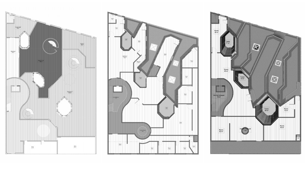
- RESULTS AND DISCUSSION –
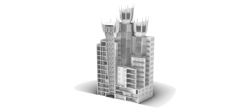
Incorporation of passive cooling techniques like wind towers into design of future urban buildings as well as retrofitting existing buildings can reduce the energy consumption of building. The built-form of the proposed Urban Wind Towers with its responsive features can provide a passive alternative to active energy extensive means.
Through use of Computational Fluid Dynamics simulations it was found that the cross-section profile of the shaft influences the air distribution rates within the adjacent living spaces. Modifying the cross-section can improve the air flow rate within the lower floors spaces which usually experience lack of air ventilation leading to thermally uncomfortable conditions. Also by modifying the window cross-section area air distribution can be modified to provide better ventilation rate in lower floors.
Urban Wind Tower system by utilizing natural phenomenons including stack effect and venturi effect was found through C.F.D. analysis to improve the air flow rate within living spaces and reduce dead zones within the shaft area.
Different degrees of intervention is possible into existing building depending upon their typology. Addition of the wind catcher improved the wind speed within the shaft in Case 1.A and 1.B and subsequently modifying the shaft sizes improved with the air distribution rates within all floor levels. Incorporation of Hot- Air exhaust reduced the merging of cool incoming air and hot inside air through stack effect. In case 4.A and 4.B it was found that one side of the shaft can be used for day-lighting purposes by removing living spaces from the subsequent side.
Using Smoke simulation of Houdini Software, wind tower inlet elements were designed to improve the wind catching capacity. Responsive elements like inlet cross-section can be modified to improve the wind velocity depending on the ambient conditions.
Traditional passive cooling systems have defined the building design for centuries and their incorporation into modern building can also lead to new building forms which can assist in reducing the energy demand of urban areas.
- CONCLUSION
High-density urban housing is one the major contributors to Urban Heat Island Effect and lack of flexibility in future intervention due to presence of multiple shareholders creates ever existing reliance on H.V.A.C. systems for cooling the living spaces. Though the urban typology differs in different cities around the world, incorporation of passive cooling systems through building design can help reduce energy demand. With growing population and rapid urbanization these typologies are subjected to rise in numbers and their building design and shape the future energy demand.
Future application of this application involves conducting energy simulation of the building design using Energy Plus through Honeybee, to find necessary wind speed at different levels using Adaptive- comfort calculator. Such research can provide optimum dimensions for shaft cross-section area as well as Window sizing. Further radiation analysis in conjecture with C.F.D. analysis can help resolve day lighting issues within these shafts through use of transparent facades on one or more sides. Future spatial arrangement patterns could be defined around passive cooling systems. Existing building with shafts could be analyzed for optimum retrofitting proposal and change in energy consumption could be compared. Future buildings can be designed through optimizing the parameters of the passive cooling system – Urban Wind Towers like window cross-section area or Wind tower Inlet cross-section to optimize the wind speed necessary for achieving thermal-environmental-conditions-for-human-occupancy.
References
– International Energy Agency, Iea. n.d. “The Future of Cooling Opportunities for Energy-Efficient Air Conditioning Together Secure Sustainable.” Accessed July 15, 2021. www.iea.org/t&c/.
“Addresses According to the Population Register.” n.d. Accessed July 16, 2021.
https://www.bcn.cat/estadistica/angles/dades/tpob/llars/padro/a2020/estruct_llars/index.htm.
“Cold Spot: Evaporative Cooling through Ceramics – Climate CoLab.” n.d. Accessed July 16, 2021.
https://www.climatecolab.org/contests/2014/urban-heat-island-effect/c/proposal/1313914.
“Continuity Equation.” n.d. Accessed July 16, 2021.
https://www.princeton.edu/~asmits/Bicycle_web/continuity.html.
“Cool Brick | Emerging Objects.” n.d. Accessed July 16, 2021.
http://emergingobjects.com/2015/03/07/cool-brick/.
Ford, Brian, and Brian Ford. 2002. “Passive Downdraught Evaporative Cooling?: Principles and Practice Environmental Design Passive Downdraught Evaporative Cooling?: Principles and Practice” 5 (January 2002): 271–80.
“Masdar City’s Wind Tower: Literally Cool.” n.d. Accessed July 16, 2021.
https://www.triplepundit.com/story/2011/masdar-citys-wind-tower-literally-cool/81091.
Mostapha Sadeghipour Roudsari. 2020. “Ladybug and Honeybee [ Legacy Plugins ].”
https://www.food4rhino.com/en/app/ladybug-tools.
Reader-Harris, Michael. 2015. “Venturi Tube Design,” 77–96.
https://doi.org/10.1007/978-3-319-16880-7_3.
SimScale GmbH, Munich, Germany. 2021. “Simscale.” Munich, Germany.: SimScale GmbH.
https://www.simscale.com/.
“Standard 55 – Thermal Environmental Conditions for Human Occupancy.” n.d. Accessed July 15, 2021.
https://www.ashrae.org/technical-resources/bookstore/standard-55-thermal-environmental-conditions-for-human-occupancy.
“Sustainability – Sustainable Urban Development – Masdar City.” n.d. Accessed July 16, 2021.
https://masdar.ae/en/masdar-city/the-city/sustainability.
“The World’s Cities in 2018.” n.d. Accessed July 17, 2021.
https://www.flickr.com/photos/thisisin.
US EPA, OW. n.d. “Reduce Urban Heat Island Effect.” Accessed July 15, 2021.
https://www.epa.gov/green-infrastructure/reduce-urban-heat-island-effect.