Studio I – Final Project – B(L)ending
01 Context
In this project we research the automization of manufacturing metal profiles. More specifically the bending of structural profiles to precisely achieve a desired curve. In this project we explore the bending of aluminum profiles which are ideally shaped for lightweight reinforced structures in automotive and aerospace industries.
The properties of this thin material allow for easier manufacturing, manipulation and transportation processes.
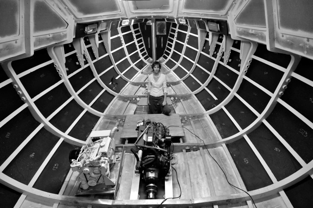
(1) Aluminum boat building. Source: dudleydix.blogspot.com
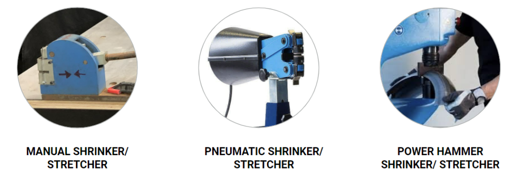
Metal shaping methods
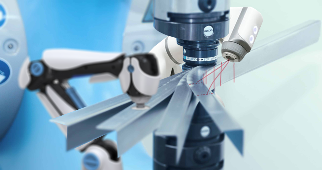
Almost any metal manufacturing process can be either manually, motorized or automatically operated.
Manual > Motorized > Automatic

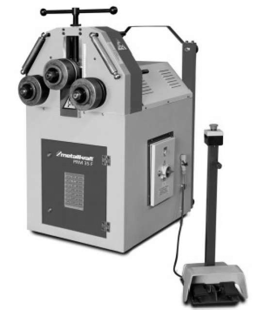
In our case we wanted to develop an automatic process on aluminum angle bending, that implied a motorized process with a predictable result on the manufacturing from the design phase.
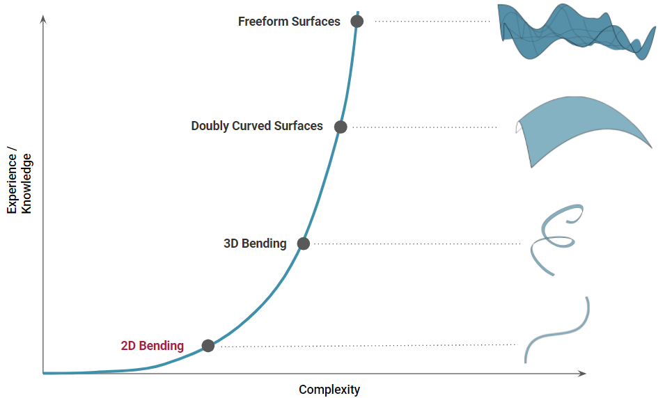
On the following table, there is a comparison among the operational dimensions (in 1, 2 or 3 directions) of manufacturing 3 different shapes of metals.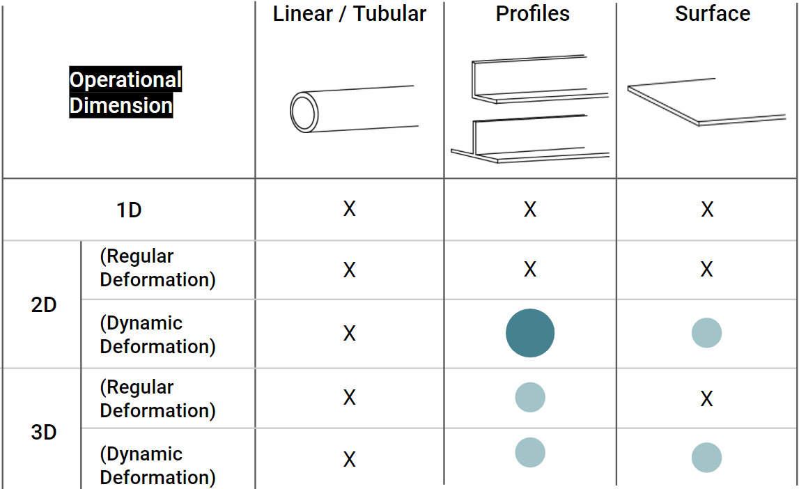
The dotted cases are still to be fully industrially developed to get the desired automatic process. Therefore, we are focused on the dynamic or non-regular deformation in 2 directions on metal angles and profiles.
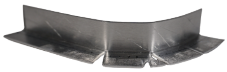
More exactly, we chose the “L” shaped angles, with identical wall lengths to ensure the biggest structural strength with the minimum amount of material with symmetrical results, also giving us the chance to test the deformation on both sides.
“It takes three years to learn how to wield a hammer accurately. It takes at least ten years of training to learn how to create any and every kind of curve” – Jiro Kunimura Master – Craftsman for the Shinkansen
“I’ve built templates when using a shrinker/stretcher, but there is a lot of time wasted when constantly moving from working on the piece to the template itself” – Luciano Carizza – Technical advisor
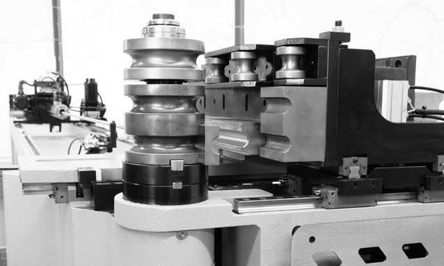
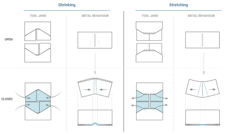
Shrinking / Stretching
Definition: A tool for deforming metal, consisting of mechanically shrinking or stretching a specific area
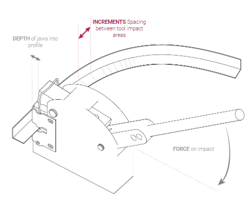
Mechanical Behavior
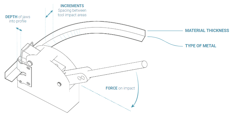
Parameters
02 Computation & Workflow
Testing
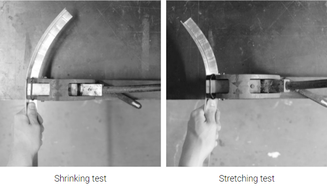
Goals:
- Compare shrinking and stretching results
- Test its regularity with constant repetition
- Test incremental variations and compare to curves

Test:
- Sheet metal thickness: 0.8 and 1.3 mm
- 14 different increment values (5 - 35 mm)
- 3 depths: 6, 12 and 18 mm
- Length: 15 cm
- Aluminum 1050T
- ‘L’ section profiles (20x20mm)
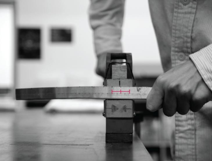
Manual Testing Results
- Force variable fixed by blocking the ending angle
- Better results on shrinking, also preferable for structure facade
- 0.8 mm aluminum required less mechanism stress
- Best depth 18 mm
Process
Fixing all other parameters, we variate the increment distance and study its relation to the change in the degree of curvature.
Computation
Varying only the increments, we get record the curvatures for each iteration and plot them
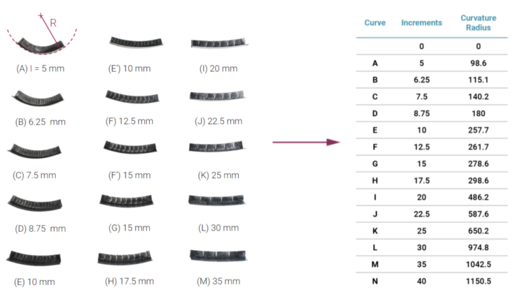
Using linear regression, we find the relationship between Increment Distance and Curvature
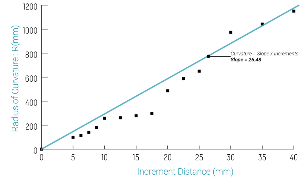
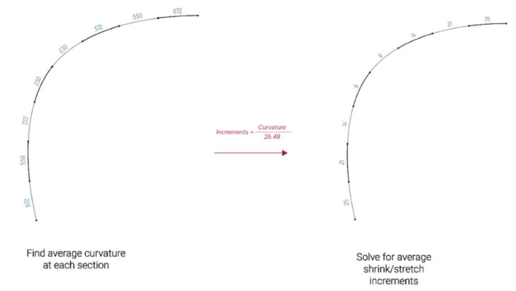
We find that the slope m = 26.48, which gives us the relationship: Increment Distance = 26.58 * Radius of Curvature

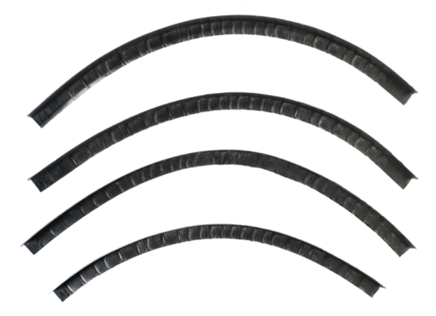
After testing 4 rods under the same conditions of equal increments, depth and force of cutting, we realise that the tool is not repeatable and we get very different curves.
Robotics
If we can confidently bend something else repeatably, then the robot can create a dynamic template by replicating the desired curves.
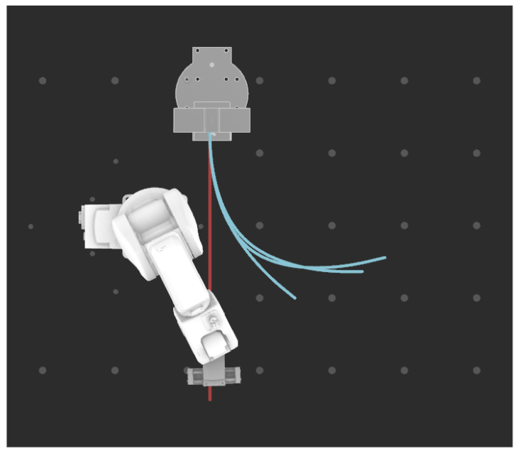
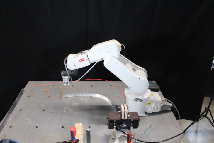
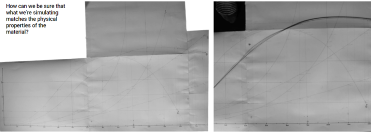
We fix the 2 edges of the polycarbonate rod, setting it’s boundary conditions as fixed, record its shape, and import it shape to Grasshopper and check if we’re able to replicate the curvature by simulating it with Kangaroo.
</p>
03 Design & Fabrication
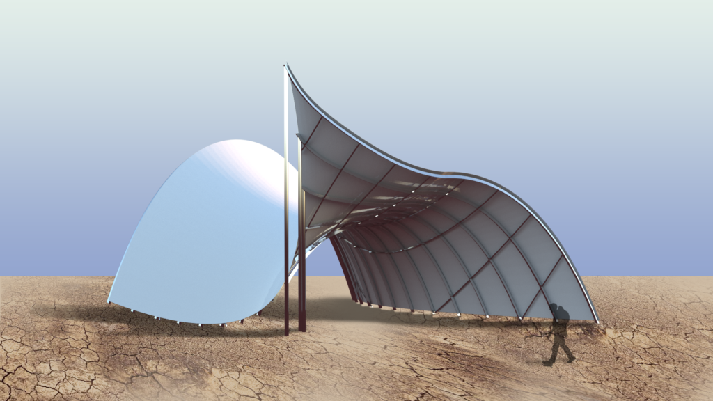
Our design intent was to create an organic modular shape that could interact with the reflection of the light where our metal structure would become the skeleton of our shape.
Our first decision was to start from a double curved shape that would deform the structure symmetrically in two directions.
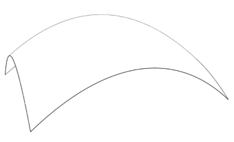
Double curvature surface
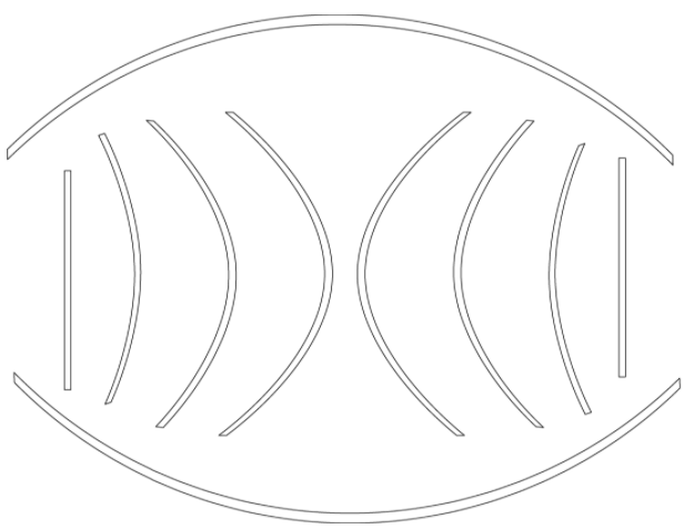
Then we defined the main structure that would adapt to the original surface or skin, where we needed 2 identical horizontal profiles, tied with 2 straight vertical profiles on the sides and 6 curved profiles in between (10 pieces in total).
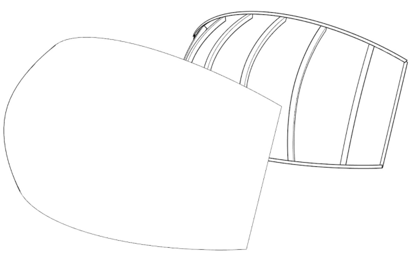
Reflecting skin over the metal structure
Exploded view of the structure
Then we defined the final dimensions of our design making it big enough to generate interesting curves in our design disregarding its weight as the material offered an excellent advantage.
The final piece would not be much bigger than 1 meter long by 40 cm width and 36 cm deep.
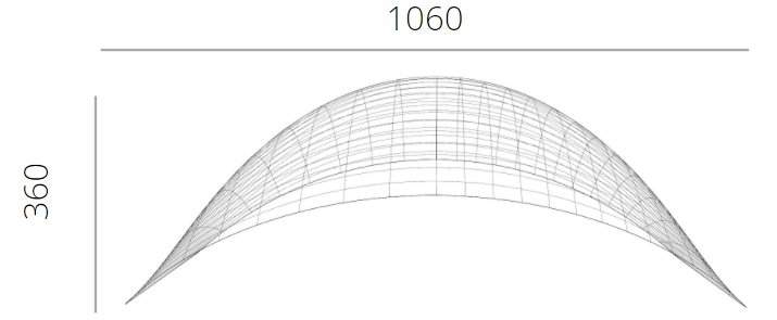
General Dimensions
Structure and joints
The final structure would be built in 20×20 “L” shaped profiles made of aluminum 1050T alloy. This specific aluminum will give an even lighter condition and easier manufacturing in bending and assembling processes.
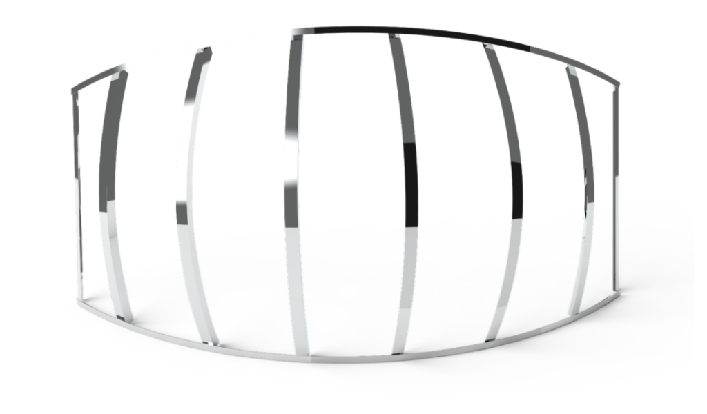
Metal structure
10 pieces
2x 400 mm (straight)
2x 485 mm
2x 612 mm
2x 687 mm
2x 1160 mm (top and bottom)
32 rivets
D4,2mm holes
d4mm rivets
M4x10 bolts
M4 nuts and washers
The 10 pieces of the structure would be joined together with 4mm rivets (2 on every joint) as shown below.
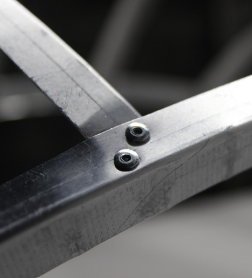
Riveted Joint
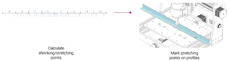
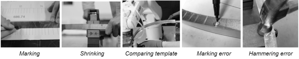
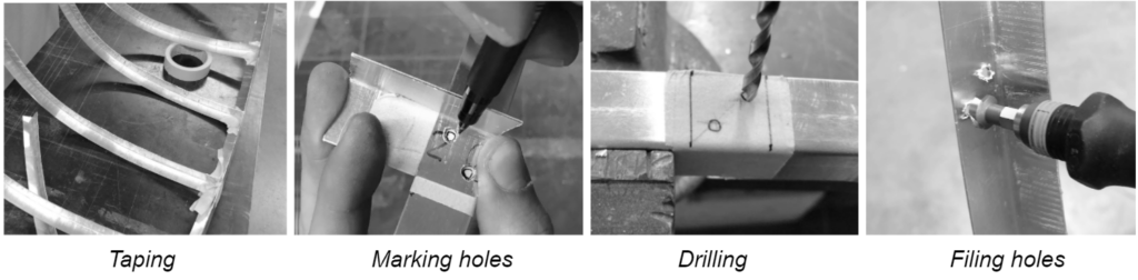
Fabrication process
In the profiles manufacturing we followed the next steps:
For the structure assembly, we first joined the structure with bolts, nuts and washers to test the prototype and the additional materials of the skin.
Testing with light and reflection
On our lighting test we worked on both a reflective material and direct illumination.
The material we used as the skin test is a PVC and cotton based fabric with a mirror effect layer that while wrinkling it along the structure would give an interesting contrast over the aluminum skeleton, but not consistent enough.
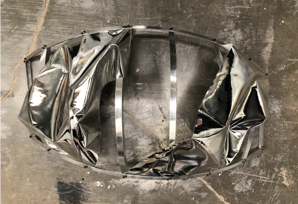
Skin material
Additionally, we tested a different lighting with direct illumination from RGB LED stripes hidden behind the aluminum structure, but this required a full research on programming the different colors and positions of this light. Below there are some examples in white light.
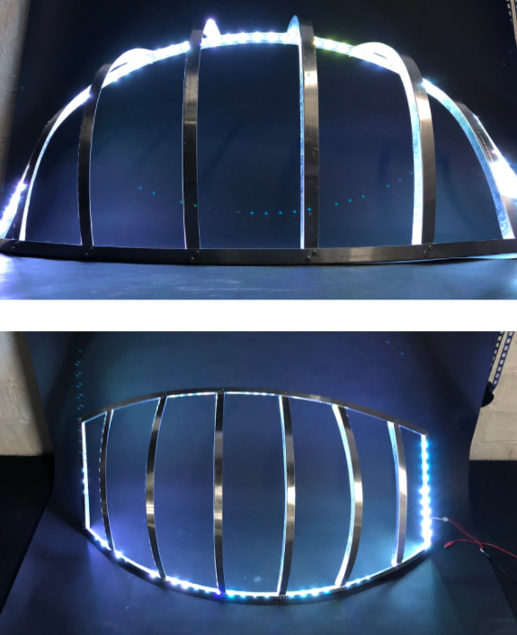
White LED light test (top and front views)
04 Potential & Next Steps
We are still scratching the surface of roboticizing the custom metal forming process. Starting with understanding metal bending in 2D, this knowledge is imperative to be able to extend this process into 3D surfaces and beyond.
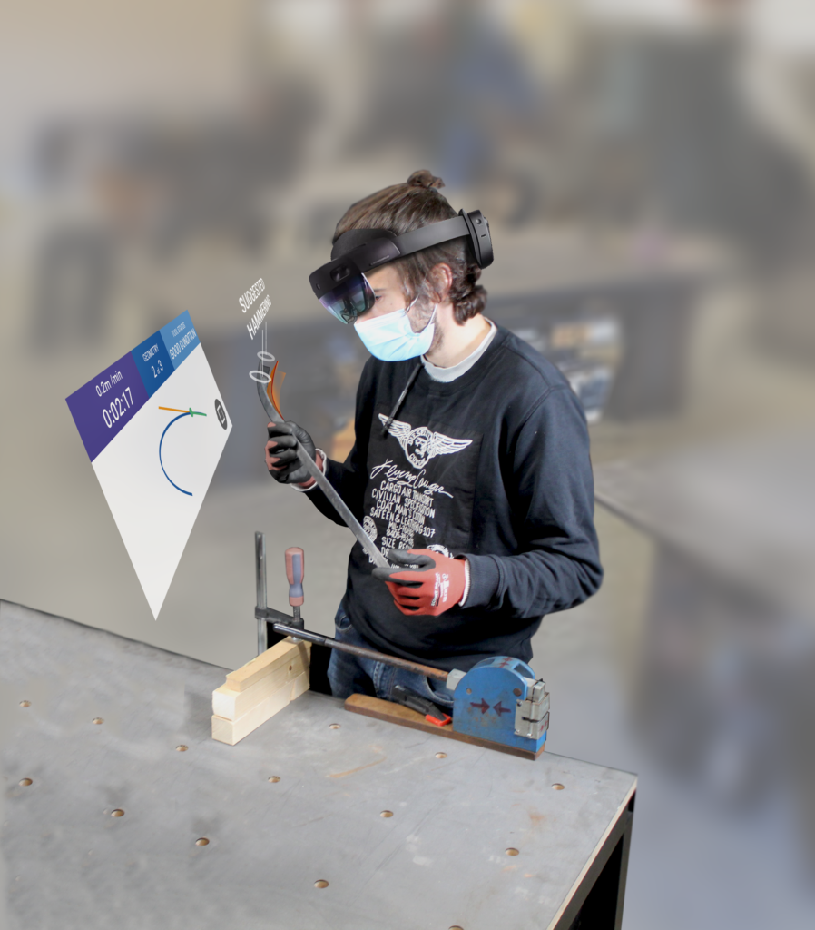
Furute iterations could include sensors for feedback and correction or AR guided tools.
Possible substructure with custom bent L-Profiles
B(L)ending is a project of IaaC, Institute for Advanced Architecture of Catalonia developed in the Masters of Robotics and Advanced Construction in 2021/22 by:
Students: Alfred Bowles, Alberto Martinez , Jordi Villanova
Faculty: Raymond Krenmueller, Marielena Papandreou, Luciano Carizza