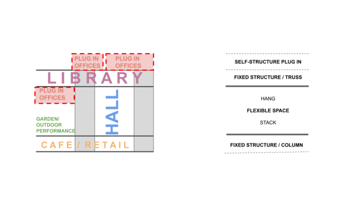
What sort of structural strategies allows us to have uninterrupted floor space that would allow us to plug in spaces in the future if needed?
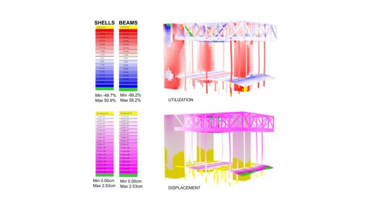
The first step was to do an overall analysis to see if there were any unusual behaviours. From this initial analysis of all the structural elements for all the load cases, both the shells and beams are being utilized at a maximum of 50 and 58% and minimum of -49%% and -99%.
This shows that there are certain elements that are not being utilized at all. In the next set of analysis, identifying these elements by studying them individually and by each load case will be helpful.
By identifying them it will show areas where more space can be adding either by stacking or hanging depending on where these elements are located.
The area where the floor is cantilevered do not perform well and either need more support or the height of the members on the floor increased.
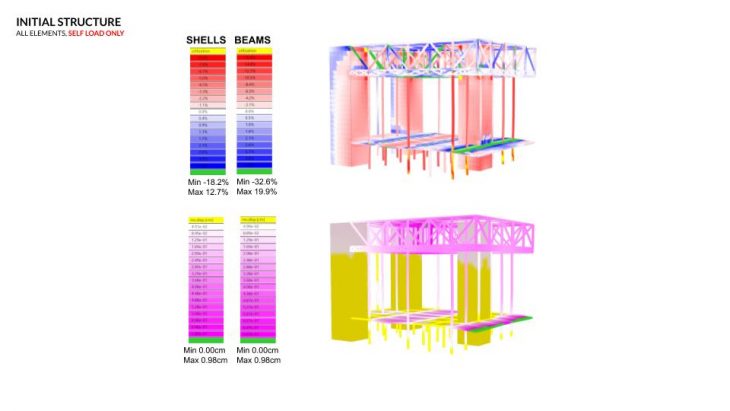
With only self-load the cores on the left are working to stop the structure from caving in as the centre part of the building has fewer supports. The beams/truss at the centre of the upper floor is working the hardest. Beams and floor on the lower floor where they span 10m are also working more than the other parts.
There is little or no displacement in the lower half of the cores as there are columns here that are also supporting the structure. Other than the cantilevered part and area of 10m spans of the lower floor most of the displacement is in the upper part of the building. The most displacements are in the central area where there are no vertical supports.
Here, the cores behave very differently to when only self-load is applied which is in vertical whereas the wind load is horizontal. The cores perpendicular and facing the wind direction are being utilized the most here. The columns closer to the facade where the wind is being applied is also working harder than the other columns.
Most of the displacements are in the upper beam elements where there is only one core. Since there is only one core taking all the lateral forces compared to the other end where the structure is more stable due to the two cores most displacements are happening here. Adding a shear wall on this side will make the structure more stable. The maximum displacement is only 0.55cm.
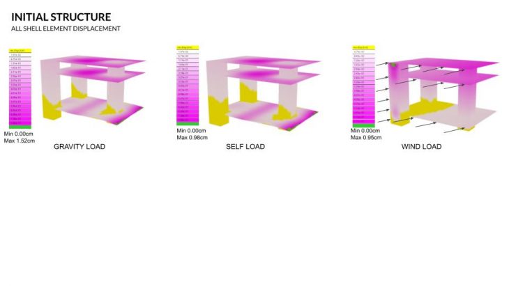
For both gravity and self-load, the cantilevered part of the lower floors and the middle area of the upper floor and roof are being displaced the most, hence, would need additional support or increase the size of the support members. There is little or no displacement in the cores for both the gravity and self-load, especially at the bottom. For the wind load, the displacements are more in the upper region of the structure, the upper floors and the top part of the cores. The structure here is trying to resist the lateral movement caused by the wind. In other words, it is trying to stop twisting from the top in anti-clock direction.
 Similar to the floors and cores the area where the beam elements are being displaced the most are the same, the cantilevered areas and the upper floor. Here, the columns at the bottom are being displaced the least and are very stable, whereas the upper areas are being displaced more.
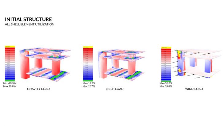
The cores for the gravity and self-load are not being utilized much except the top left corner for gravity load and the left side for self-load. This is happening because the cores are taking all the loads of the floor and trying to prevent bending inwards so the outer side of the cores are working more than the other parts.
The areas where the floor intersects the cores or the columns are working the most as seen in green here. The start of the cantilevered floor is also being utilized the most. For the wind load, the cores are being utilized much more than for the other two loads at a maximum of 39% compared to only 20% and 12%.
The cores in the wind load are preventing lateral movement. There is a direct relationship between the with the displacement and the utilization of the shell elements.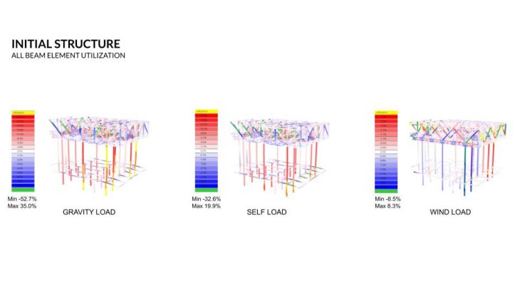
The columns on the bottom half of the structure are not being utilized much for gravity and self-load. Only the beams in the lower half are being utilized to hold up the floor mass.
The upper floor seems to be doing most of the work here. This could be the case as the mass here is more as well. Among the upper beam elements, the diagonal members are being utilized the most.
In the case of wind load, the columns closest to the facade where the wind is applied are working the most. The utilization for the beam elements on the upper floor are not concentrated in one area but rather scattered all around.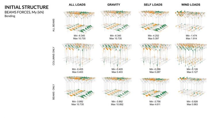 Bending for both columns and beams seem to be equally distributed in both directions for gravity and self-load. In the case of wind load, there are areas where bending is unevenly distributed for the beams, with peaks in a certain area and little or no bending in other areas.
Taking a closer look at the beam forces we noticed that the columns are in more compression than in tension for gravity and self-load whereas in the wind load they are more in tension towards the facade where the wind load is applied. We will have to add diagonal members to adjust the columns.
For the beams, most of the tension and compression are in the upper elements except for the wind load where it is evenly distributed.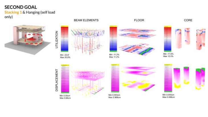
The overall structure is still stable after adding floors to the existing structure. There is little displacement to both the beam and shell elements and the utilization is at a maximum of 20% only. 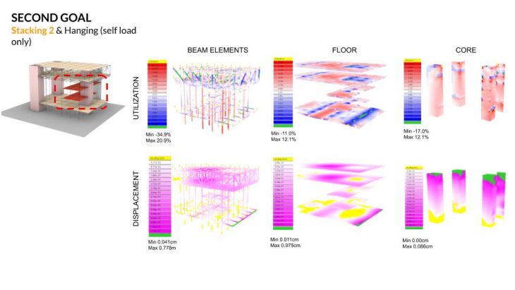
More floor was added on top of the same area to see if the utilization and displacements change. The results show very little change in displacement for all the elements. (beam, floor and core) It seems that the structural elements are over-specified and can start looking at reducing the size of the elements so they are being used efficiently. Also, looking at all the load case instead of just self-load. Hence, more loads can be added to this existing structure. 
Before reducing the size of the structural elements we wanted to test hanging floors from the truss to see how it affects the structure. Here, all the load cases are observed but isolating only those elements that would be affected by the hanging loads. The initial results showed displacement where the distance between the hanging cables were more than 10m. We changed it to 5 meters and this helped reduce the deformation from 2.43cm to 1.97cm. We also see here that the beam and truss are not underutilised and working at 40%.
From the initial analysis, we also noticed that the cores were being under-utilized so we saw this as an opportunity to hang floors from areas where they were being utilised the least. Here, we’ve attached a cantilevered floor to the core. The utilization of the core increases but is still stable and not deforming too much. The beams supporting the additional floor show little deformation and are also stable.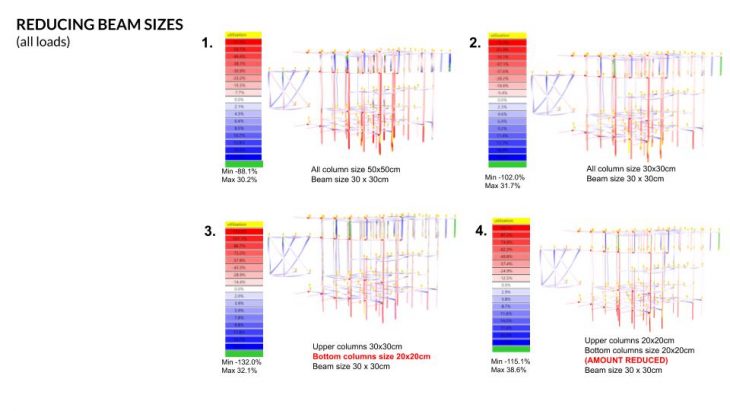
We then went through the process of incrementally reducing the cross-section of the columns and analysing the results to the columns and beams. The columns were chosen as they are the structural elements that are being underutilized the most.
The columns were reduced from 50x50cm to 30×30, then reduced only the bottom half to 20x20cm and got utilization of 32.1%. We felt that we could reduce the number of columns on the ground floor as they were the ones not being used efficiently.
The number of columns on the ground floor was reduced and also the size of all the columns to 20x20cm. 
From the final analysis on the entire model, some parts of the structure are still not being utilized efficiently and stacking or hanging more spaces is possible if needed.
With this, we can conclude that this structural strategy of creating a big truss system on top and a very stable bottom structure to have maximum open floor area allows us to plug in more loads in the future if and when needed.
This is a project of IaaC, Institute for Advanced Architecture of Catalonia at MaCad – Master in Advanced computation for Architecture and design in 2020/21 by:
Students: Amar Gurung, Marissa Ridzuan and Pedro Ribeiro
Faculty: MANJA VAN DE WORP and HANNA LEPPERØD (Assistant)