OVERVIEW
The following structural analysis and structure optimisation studies are related to the studio project ‘Sing Ging’ which introduces a system to rewild dense populated urban environments, within an abandoned building. The structure of the project is based on a 3D rectangular grid that supports different soil modules with different wieghts, within its composition. This analysis is divided in two iterations one with cross bracing elements made of bamboo with timber structure, and the second one with cable cross bracing elements with mixed timber and steel structure. The two studies were carried out to choose the optimal structure for the mentioned project, optimizing the use of different materials, and the general stability of the structure.
CASE STUDY
The project presents three case studies from similar compositions to study similar structural approaches. The first example shows how compression and tension are working through the structure and how cantilevers transfer the loads to the supports. The structure presents a foot like shape, aiding the structure to create a more stable composition. The second example shows a particular type of supports that also work as cross bracing structural elements, creating a lattice structure of bamboo. We aim to use bamboo as cross bracing structural elements within the main structure to rigidize the rectangular 3D grid, stabilizing the clusters loads. Finally, HABITAT 67 – Quebec, Canada’s system presents a standing structure formed by stacked boxes. The boxes require extra support for stability. The structural frame is provided by concrete and steel with a rigid core and cantilevers. From this reference, the project took three main structural iterations.
- 3D Grid as structural framework with high stability in the bottom for tension and compression flow among the composition.
- Bamboo cross bracing structural elements.
- Structural cores to place the cross bracing elements inside specific sections of the structure.

Envision Pavilion – Sou Fujimoto
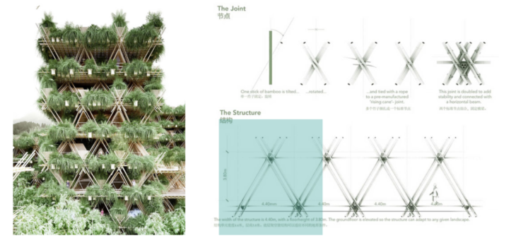
Penda – Bamboo City
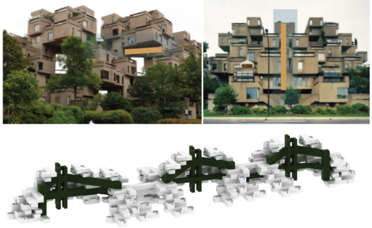
HABITAT 67 – Quebec, Canada
SITE
The proposed site is the State Theatre inside the north point in Hong Kong. This building was used as main support for our structure, which rose from the bottom until connecting it to surrounding buildings.
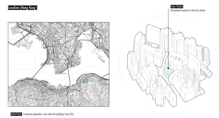
Figure 1. Site proposal
PROJECT BRIEF
The strategy begins with a 3D Grid starting from the bottom of the theatre to then connect the surrounding rooftops and buildings.
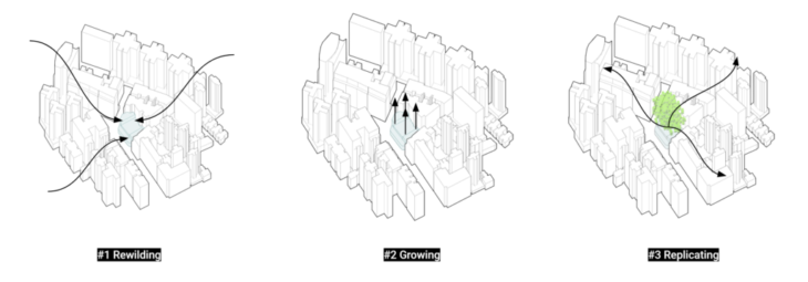
Figure 2. Project conceptThese spaces form clusters depending on different environmental conditions.
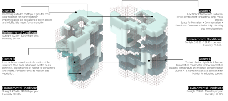
Figure 3. Environmental Clusters
Each cluster is then populated with the soil modules around the structure. The intervention presents a Micro scale starting with the soils modules around the grid structure, to a Macro scale implementing vertical circulation, and floors as paths connection the soil modules.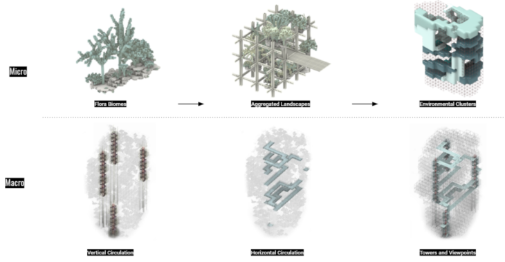
Figure 4. Strategy implementation
ANALYSIS OBJECTIVES
The following structural analysis is divided in three sections. First the implementation of floor shells for live loads (humans), cross bracing elements among the structural grid, and circulation towers surrounded by structural cores to add structural stability, analysing its utilization, displacement, and axial forces (Figure 5). Second, the displacement simulation of the inner structure of the soil modules (Figure 6). Finally, the position of modules was optimized to find the best placement to reduce the utilisation, and displacement of the main structure.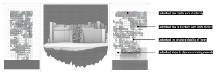
Figure 5. Objectives within structure
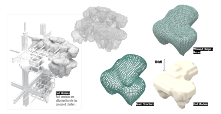
Figure 6. Soil modules structure and dead load
ANALYSIS TARGET
The structural analysis targets the bottom section of the structure to study the main structural frame and supports of the project. This section has three main clusters; the main circulation tower, and the implementation of structural cores for cross bracing elements.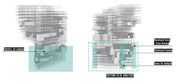
Figure 7. Section of the project to be analysed
STRUCTURAL PRINCIPLES – MODELS OVERVIEW
This structural analysis presents two model iterations. M00’s cores are positioned in the middle in the edges of the structure, also this iteration presents a full 3D Grid. M01’s cores are positioned only in the edges and have a significant reduction of structural elements around the floors and clusters, as shown in Figure 8.
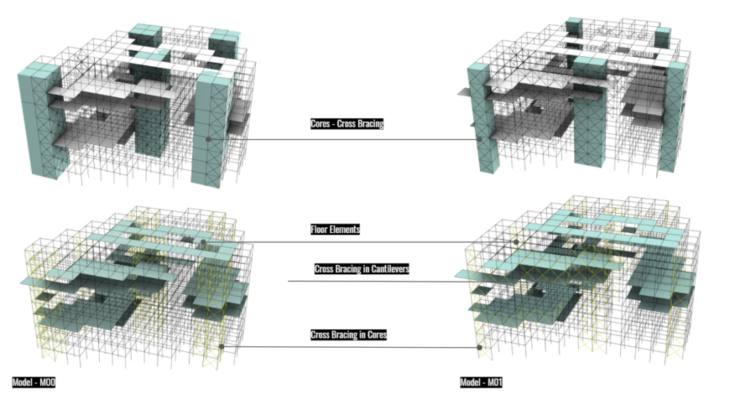
Figure 8. Analysis Overview M00 and M01 comparison (Cores, Floors, Cross Bracing)
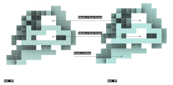
Figure 9. Analysis Overview M00 and M01 comparison (Cores and Floors)
M00
This model present the implementation of cross bracing elements within structural cores all around them, which means that these elements are positioned in the XY Axis in both directions. The floors as shells, simulate the soil implementation within the clusters, which not only hold live loads (people), but plants and trees as well. We aim to have an optimized structure to implement these elements in our project.
Load Cases:
- Load Case 00 – Gravity
- Load Case 01 – Floor: 10.0 kN/m2
- Load Case 02 – Wind_01 – Left Facade 30 kN
- Load Case 03 – Wind_02 – Front Facade 30 kN
Cross Bracing:
- Floor – 20 cm
- Column – 20 x 20 cm Timber Section
- Frame – 20 x 20 cm Timber Section
- Brace – 50.0 x 5.0 mm Bamboo
Material:
- Floor: Timber
- Column + Beamn: Timber
- Brace: Bamboo
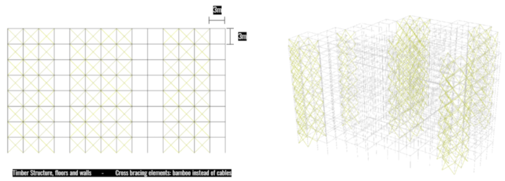
Figure 10. Moo cross bracing elements and structural grid
M01
This model present the implementation of cross bracing cable/steel within structural cores. We implemented Steel Beams in this proposal to support the cantilevers, and cable as cross bracing elements instead of bamboo. Also the cross bracing elements are positioned only in the X axis on the front, and in the Y Axis on the left facade of the cores, as a method to reduce the number of elements within them.
Load Cases:
- Load Case 00 – Gravity
- Load Case 01 – Floor: 10.0 kN/m2
- Load Case 02 – Wind_01 – Left Facade 30 kN
- Load Case 03 – Wind_02 – Front Facade 30 kN
Cross Bracing:
- Floor – 40 cm
- Column – 30 * 30 cm Timber Section
- Frame – 10 * 10 cm Timber Section
- Brace – 5.0 * 2.5 mm Cable
Material:
- Floor: Timber
- Column: Timber
- Beam: Steel HEB 100
- Brace: Steel
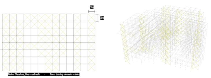
Figure 11. M01 cross bracing elements and structural grid
3D STRUCTURAL ANALYSIS
The structural analysis is divided in three sections. First analysing the utilization of the structure under different load stresses. Second, the displacement of the structure, helpful to implement more structural cross bracing elements. Lastly, The Axial forces to better understand how elements are working in compression and tension, also to see the bending moments of the cantelivers.
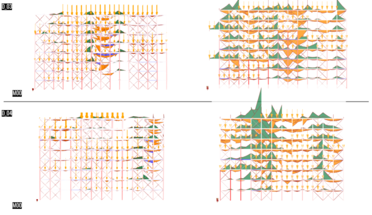
Utilization – Self weight + Live load + Modules load | M00 – M01
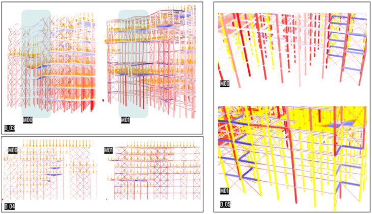
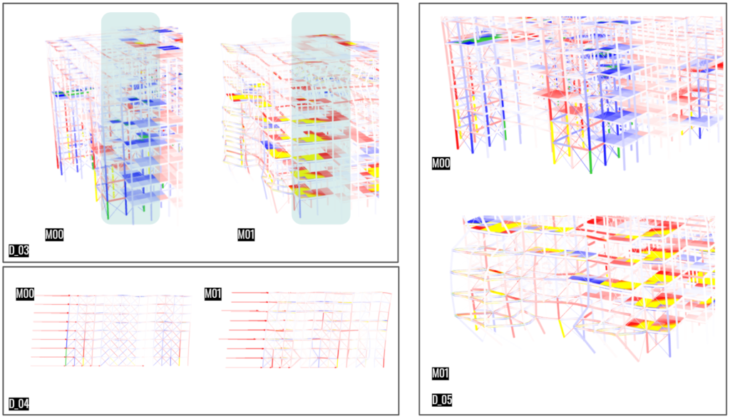
The M00 Model shows 10% less utilization compared to M01 Model, This could be due to the reduction of the core elements for cross bracing addition in M01. M01 shows a better distribution of forces within the main structure, the cantilever elements look more stable with less utilization within their floors, transmitting their forces to the cores and to the annexed columns. Due to the addition of cross bracing elements attached to the neighboring cores, D_03 shows a lesser utilisation and deformation of cantilever elements. The forces are transmitted to the neighbour structure, which is evident in the columns with higher utilization. D_04, shows in section, how the reduction of cross bracing structure does have an impact on the utilisation of the elements, though the overall structure in M01, looks under more stress compared to M00. The neighbour core beams are working in more stress in M01, which shows a better distribution of forces transferred to the cores, this can be seen in D_05.
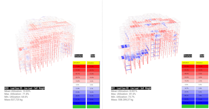
Figure 12. Utilization Comparison – Dead + Live loads M00|M01
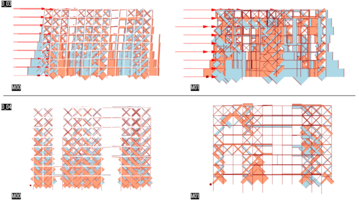
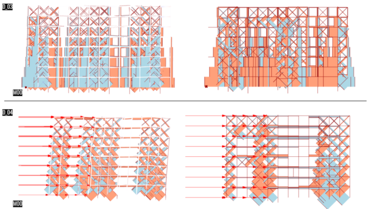
Utilization – Gravity + Wind Load Left Facade | M00 – M01
At the moment of applying wind loads, the M00 shows a high utilization of floor elements located in the middle of the structure, this shows the compression of the external cores in both sides. This is due to the reflex stressed that the cross bracing elements are applying. On the other hand, M01 – D_03 shows a higher utilization of elements within the external cores, this because of the reduction of the number of cross braced elements inside the cores. This is evident in D_04 were we see that the supports present a high deformation in M01.
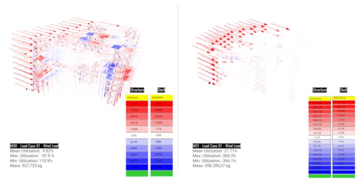
Figure 13. Utilization Comparison – Wind loads M00|M01
Utilization – Gravity + Wind Load Front Facade | M00 – M01
Same behaviour as previous wind load, the supports in lower sections get more stressed under this load as shown in D_04. Different behaviour on floor elements, were the utilization presents a low value next to the cores, this shows a stress transferring from neighbour elements to its supports, as shown in D_05.
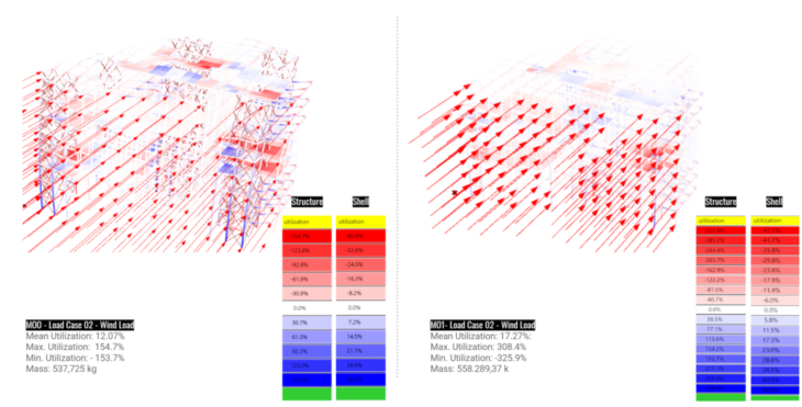
Figure 14. Utilization Comparison – Wind loads 02 M00|M01
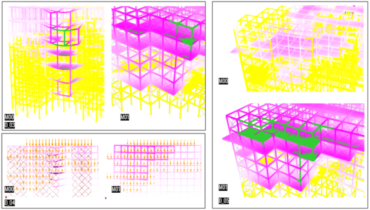
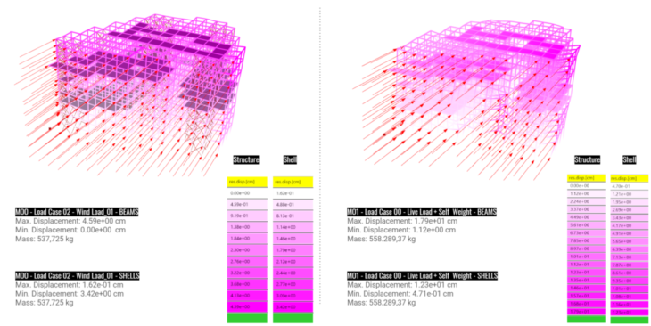
Displacement – Self weight + Live load + Modules load | M00 – M01
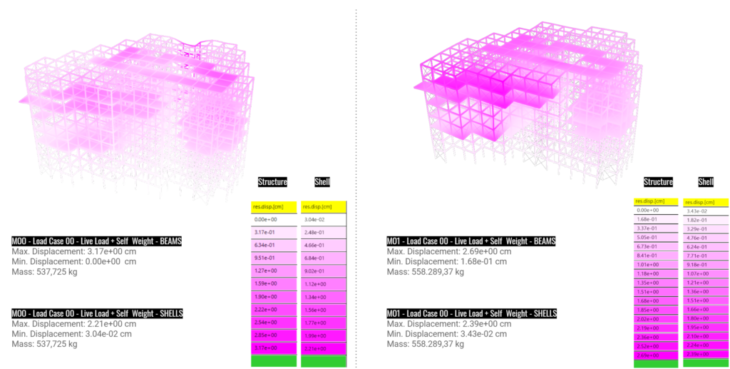
Figure 15. Displacement Comparison – Dead + Live loads M00|M01
The displacement of the elements in cantilever in M00 are much higher than in M01 as shown in D_03, this is due to the addition of cross bracing elements in M01 that allows force transfer to the core elements and then a stress distribution to the neighboring structural elements. D_04 shows a different deformation of the structure, where M00 presents a high bending moment in cantilevers, different from M01 which shows a more stable structure; though presenting a full deformation of an entire section due to stress transferring.
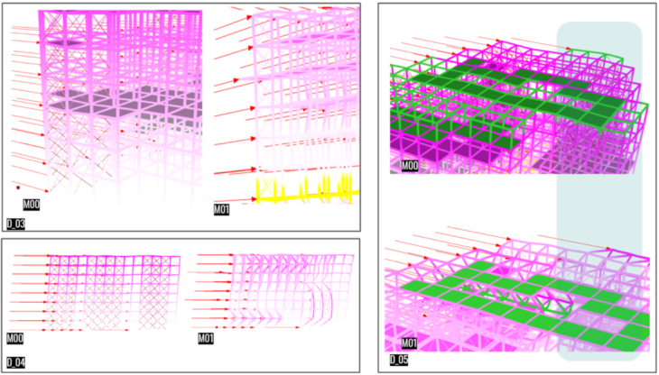
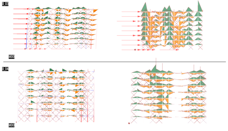
Displacement – Gravity + Wind Load Left Facade | M00 – M01
The high deformation in the bottom of the structure in M01, is presented due to the reduction of cross bracing elements as shown in D_04. The upper sections of the floor corresponding to the paths from one access tower to the other, present a really low affectance, and moreover a wave like deformation due to the reflex froze from the core shown in D_05.
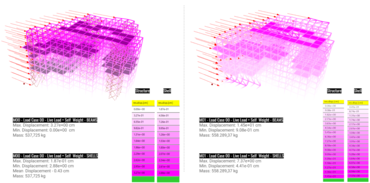
Figure 16. Displacement Comparison – Wind loads M00|M01
Displacement – Gravity + Wind Load Front Facade | M00 – M01
Similar to previous analysis, the deformation of the structure when wind loads are applied are much more higher in M01 than in M00. The right section of the structure in M01 gets a higher deformation from the rest of the composition due to the reduction of cross elements. Also as this section does not possess cantilever elements, its composition is less dense.
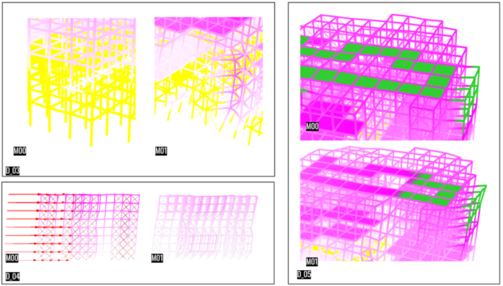
Figure 17. Displacement Comparison – Wind loads 02 M00|M01
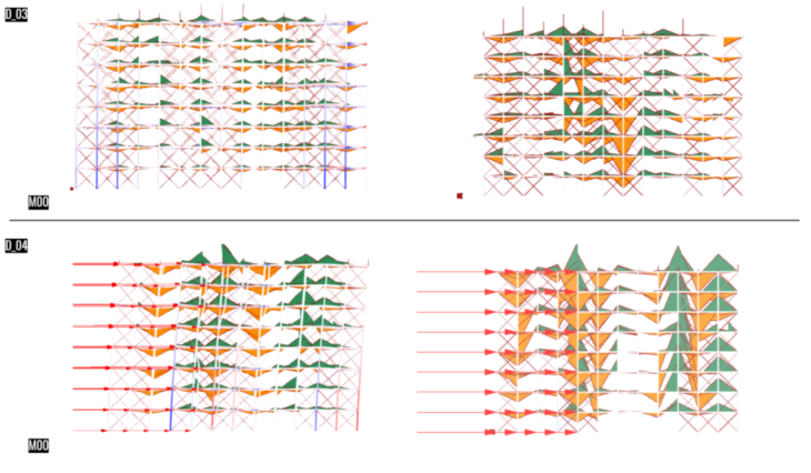
Stress Nx Axial Forces – Self weight + Live load + Modules load | M00 – M01
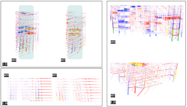
The Axial Forces in M00 present a high compression in its supporting elements, In D_03 the comparison shows the difference of designing a more dense structural frame with bigger cores and more rectangular portico-alike structure, compared to M01 which has thinner cores and less structural frameworks. Most cross braced elements in M00 as shown in D_04, are working in compression, which is not the same in M01 which works more in tension, due to the cantilever displacement.
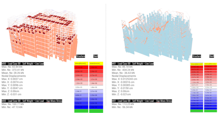
Figure 18. Axial Forces Comparison – M00|M01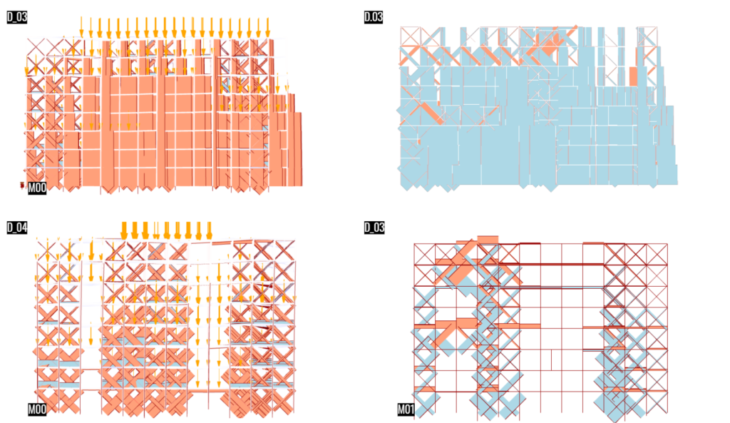
Stress Nx Axial Forces – Gravity + Wind Load Left Facade | M00 – M01
In this case, both models start to work in tension and compression more evenly throughout the composition. This shows that the compression and tension elements work more effectively once under force transferring, showing how the structure applies its structural properties.
Stress Nx Axial Forces – Gravity + Wind Load Front Facade | M00 – M01
The models apply the same principle as explained before, In D_04 the beam elements are working in both tension and compression, where the middle of the structure in M01, shown in D_04 work more in compression in the left section due to the cantilevers and more in tension on the right side. The middle of the structure as it does not have any supporting element, compresses the beam elements and transfer the tension flow at the top to the rest of the structure (how in D_04 – M01).
Stress My Axial Forces | M00 – M01
The bending moments are higher in M01 compared to M00, this is simply because there are more elements in cantilever with less structural supports. The M00 with its solid structural frame, reduces the bending moments within its elements.
Same as previous analysis, the bending moments are higher in M01 as shown in D_03. While the moments in M00 show a similar bending Force throughout its whole composition.
OPTIMIZATION OF THE SOIL MODULES
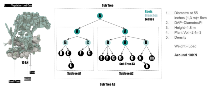
Figure 19. Loads in soil modules
The structure of the modules was optimised in terms of displacement and utilization to propose a better internal stability as support of the soil. The modules has a dead load of 10kN which comprises different types of vegetation and soil.
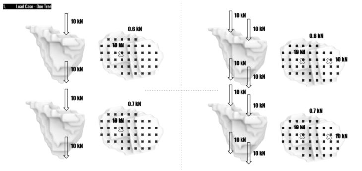
Figure 20. Load Case for analysis
Loads and Support Displacement Analysis
The displacement of the modules in regards of the main structural implementation was succesful as it wraps the soil with optimized shapes. These shapes are knitted in ratan with inner structural framework as previously shown in Figure 6. To illustrate the hanging soil structure supporting the vegetation and its own weight we can refer to the following image.
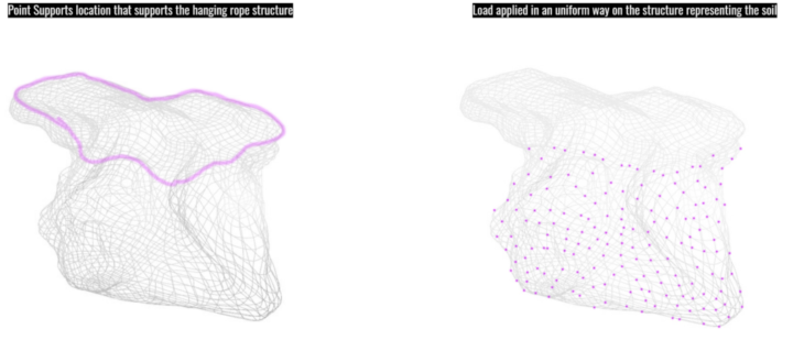
Figure 20. Supports
Changing the thickness of the ropes allow a modification in the the form , multiplying the thickness by 2 results in a form alteration of the clusters.
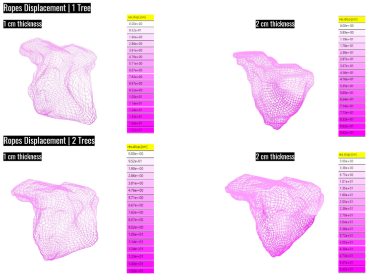
Figure 21. Displacement
Modules Placement Implementation
The optimization of the modules chooses from the position of 9 instances of each module inside the structural grid (27 slots), which objectives are:
- Maximize Utilization for a better distribution of the weights
- Minimize Displacement of the structural elements (beams and columns)
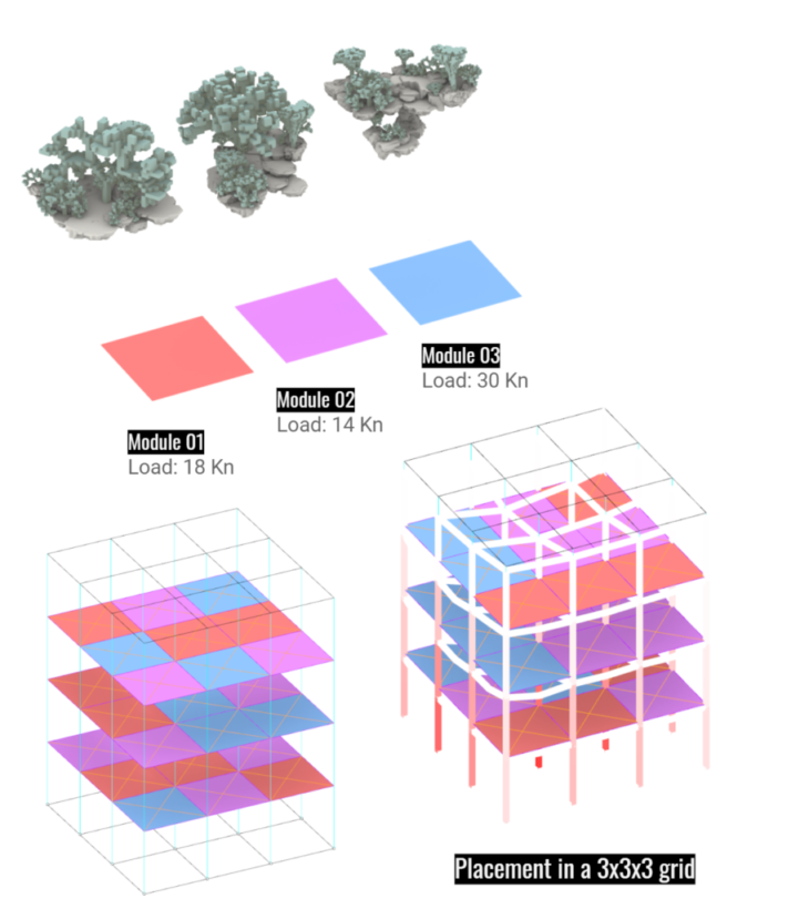
Figure 21. Module placement
Each module test different loads to search the less utilization and displacement from the proposed structure.
Figure 22. Module placement optimization
Modules Placement Optimization
The modules are distributed equally across both levels and plans, making sure all structural elements work together. Heavier Modules (blue) are placed in the lower slots, decreasing from five in level 0, three in level 1 and only one for level 2. There is an even distribution of different types of modules across levels, but it is also attempting to keep the heaviest concentrated in the bottom.
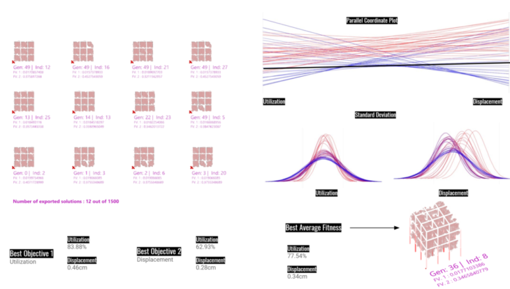
Figure 23. Genomes and average fitness
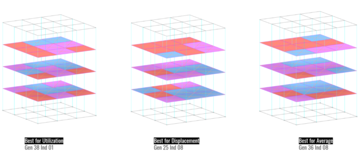
Figure 24. Optimization conclusions
CONCLUSION
The M00 presents a better structural stability, this could be due to the implementation of bamboo as cross bracing elements. The stress transmitted to the bottom of the structure is high, therefore the supports should be attached to the pre-existing structure of the theater. The cantilevers work better in Mo1, which suggest the translation of the cross bracing implementation to M00. This means, connecting the cantilevers to the cores through cross bracing. The M00 has a high stability against wind load due to the disposition of cross bracing elements, something that it was translated to the final proposal of the studio project.
The decision of placing cross bracing elements and the module optimization could be further explore throughout the main composition. Taking the previous study of M00 and this optimisation method, was crucial to the studio project. This optimization strategy was extended into other clusters, in order to gain a deeper understanding on the sequence of modules for structural optimization of the overall structure.
CREDITS
Sing Ging – Structural Analysis is a project of IAAC, Institute for Advanced Architecture of Catalonia developed at Masters in Advanced Computation and Design (MaCAD) in 2021/2021 by students: Charbel Baliss // Pablo Jaramillo // Irene Martín // João Silva // Alexander Tong, and faculty: Manja van de Worp // Matthew Gabe