MRAC Studio 3 | MRAC 2018-2019
Faculty: Alexandre Dubor | Aldo Sollazzo
Mentors: Kunaljit Chadha | Eugenio Bettucchi Raimund Krenmueller | Starsky Lara
Project by: Omar Geneidy | Sujay Kumarji
SIMULTANEOUS REINFORCEMENT OF CONCRETE 3D PRINTING
ABSTRACT:
Three Dimensional Printing (3DP) has been introduced into the construction industry for over two decades until now, However, the scaling up of the technology is currently stagnant due to some difficulties like printing horizontal or cantilever structures and printing structures over one floor heigh. The literature encompasses several attempts to overcome such limitations either by printing supporting structures that holds up the printed structure until it dries, or by casting it in a formwork that encapsulates a printed reinforcement inside it. Or, by manually adding reinforcement while printing. However, these attempts do not tackle the issue of having a unified printing process that includes vertical reinforcement in it. This research is proposing a new process of reinforcing printed structures simultaneously while printing using a scalable, straightforward process. The process comprises of pushing multiple small wire profiles into printed layers. Together they form an overall lattice structure that binds the printed layers together and compliments the overall structural soundness of the print during and after printing by addressing the buckling and tension problems. The process is later tested against different properties so as to asses its validity compared to current procedures.

TECHNICAL PROBLEMS HINDERING SCALING UP 3D CONCRETE PRINTING
The introduction of digital fabrication technology has the potential of enabling architects to design and produce in a new way, escaping from the existing current standardized modular system (Ko et al. 2019). 3DP has been introduced into the construction scale for over two decades until now, yet there are major obstacles that are yet to be solved (Alothman et al., n.d.). In order to have the desired smooth surface, the layer height needs to be small, which increases fabrication time. Moreover, the hydration process of the printed material is difficult to control and has an affect on the structure’s load-bearing capacity and the layer to layer adhesion (Hack 2015). Taking clay as an example, clay takes some time to dry after extrusion which makes it very difficult to form a self-supporting structure. And in the case of decreasing the drying time, clay starts cracking which accordingly weakens the printed structure. This makes it difficult to print hanging shapes without a supporting structure to maintain the form of deposited clay until it is dried (Ko et al. 2019). This adds a design constrain of a maximum angle of inclination before the structure collapses (Gaudilli, Duballet, and Bouyssou 2019).For that Integration of reinforcement in the process is essential for scaling-up the technology in architectural practice and minimizing its current limitations (Battaglia, Miller, and Zivkovic 2018).
CONCEPT:
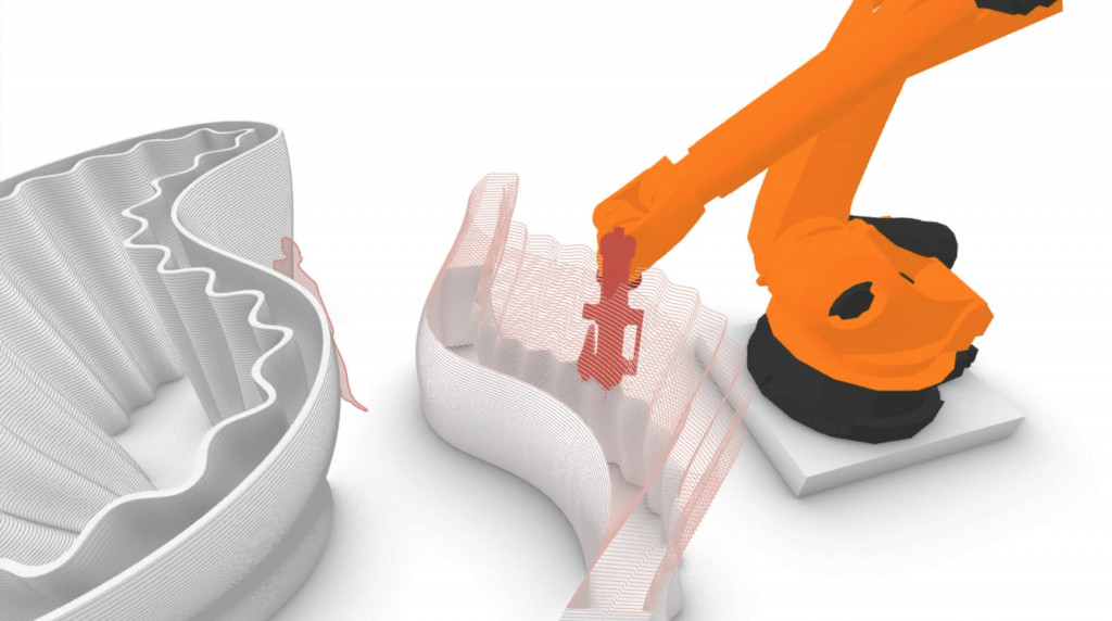
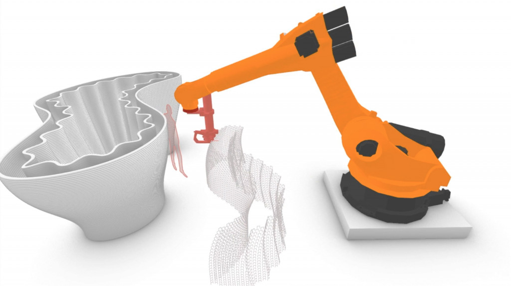
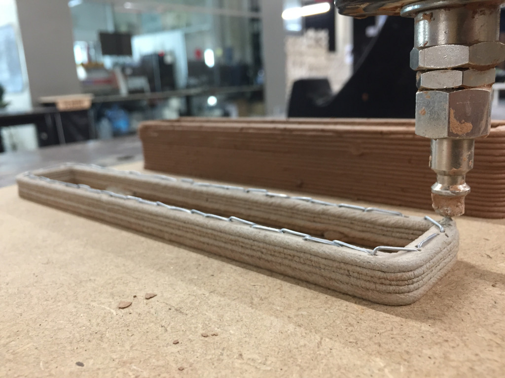
The proposed process of stapling printed structures is composed of a tool head that includes a printing nozzle and a stapler. The stapler, pushes a wire profile in to the printed clay for a half a layer deep. The stapling process happens simultaneously while printing and in a periodical manner. Together these staples profiles form an overall mesh structure wire structure that fuses the printed layers together and compliments the overall structural soundness of the print. This is ought to support printed structures (while printing and after curing) using a scalable, straightforward process that would address buckling and tension problems. Integrating the process in the large scale 3D concrete printing industry could push the geometrical limits of what could be realized; in terms of the printing height, maximum inclination & supporting openings while they are printed.
METHODOLOGY
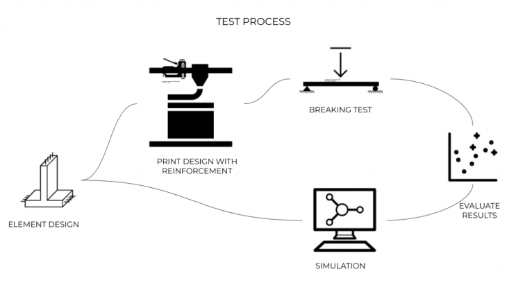
This Research is exploring the process of stapling printed layers with wire profiles simultaneously while printing so as to maintain a sturdy layer to layer connection which shall addd to the overall structural soundness of the printed layers. This research follows an experimental approach of printing different samples of geometries reinforced with staples, and others without any reinforcements. These samples later are tested against different properties (ex. compressive strength and stress ) by applying increasing pressure until failure so as to asses the validity and effectiveness of the proposed process.
VALIDATION:
While the stapling process shows tremendous potential in its ability to integrate with additive manufacturing process, the method needs to be validated in its ability to improve the tensile properties of concrete.
The only real way to conclusively prove that the process works is to test physical samples of concrete embedded with the staple type reinforcement. These samples are then subjected to tension test and the resultS are compared against an unreinforced concrete test sample to check for any change in the results.
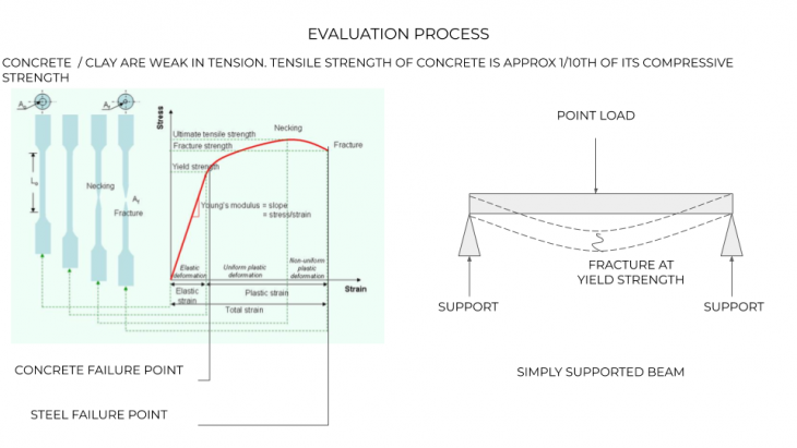
Plain cement concrete is extremely brittle when acted upon by tensile stress. The tensile strength of conrete is rougly 1/10th the compressive strength of the material. On a stress-strain curve concrete it is impossible to plot the yield point of concrete due to immediate fracture of the material. Therefore one can assume yield and fracture can be the same point. Steel on the other hand, due to its ductile properties yeilds and elongates until it fractures.
TEST
The presence of steel will add tensile properties ensuring delay between yield and fracture that could prove the working of the reinforcement. In order to verify the postulates of the evaluation process a load test was performed on a horizontal element supported on both ends with the load applied on the centre thus simulating the conditions of a simply supported beam with point load. This beam was embedded with the reinforcement and compared to a similar beam without the aforementioned reinforcement. The results were then evaluated for yield and fracture and then compared.
TEST CONDITIONS
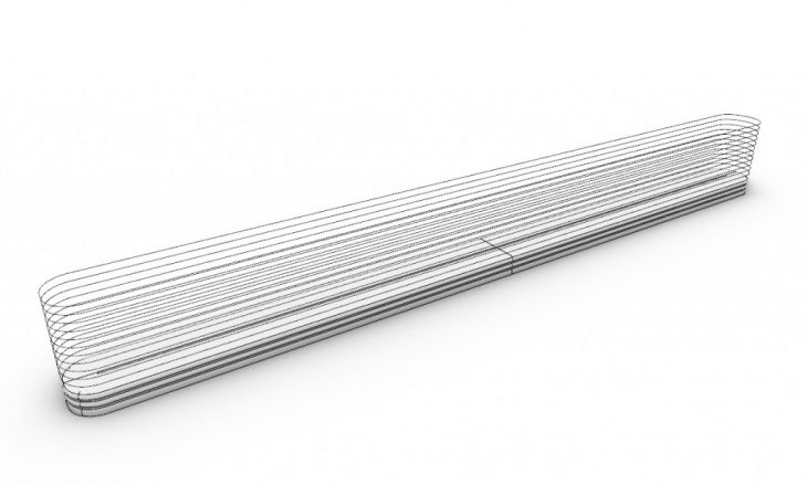
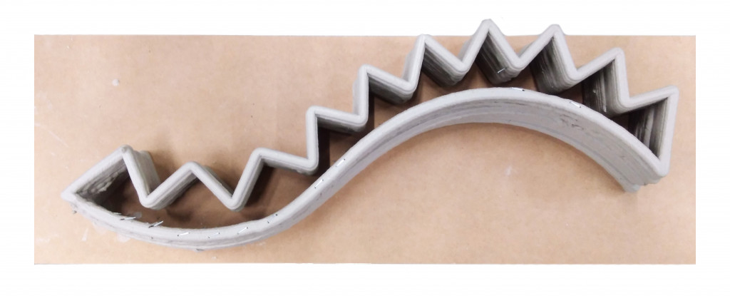
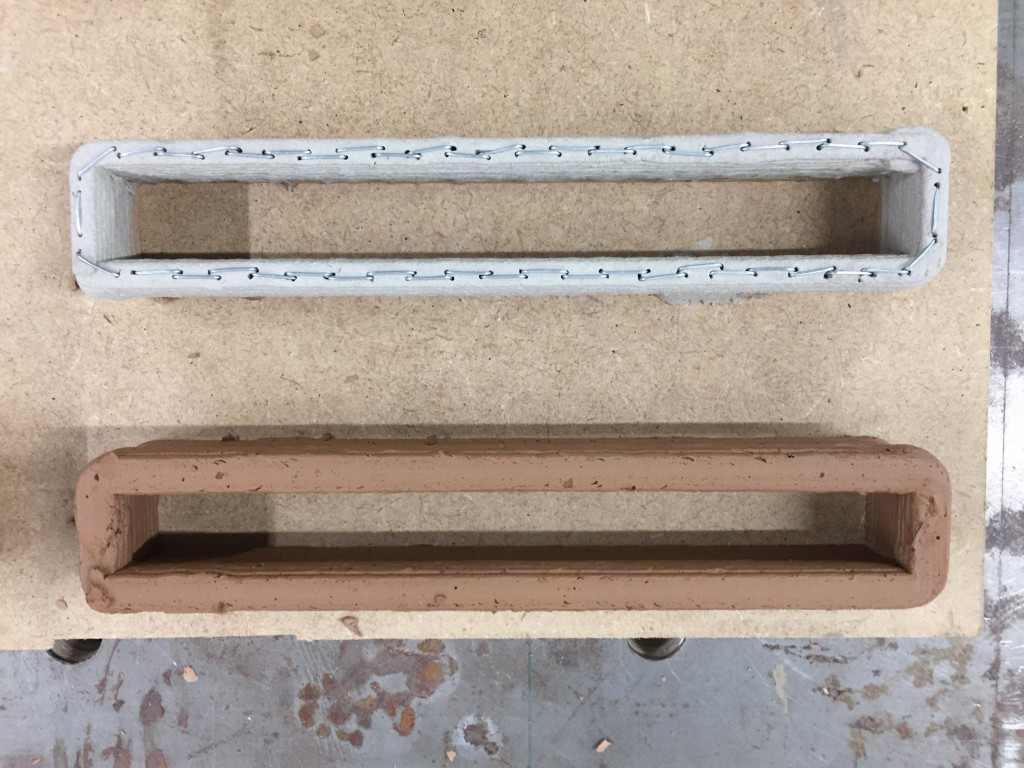
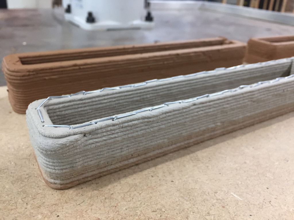
TEST GEOMETRY: The test geometry was a rectangular beam of dimensions 242mm l x 16mm b x 30mm ht.
CONCRETE MIX : 1:1 rich mix concrete of Geolite 40 rapid setting cement and sand.
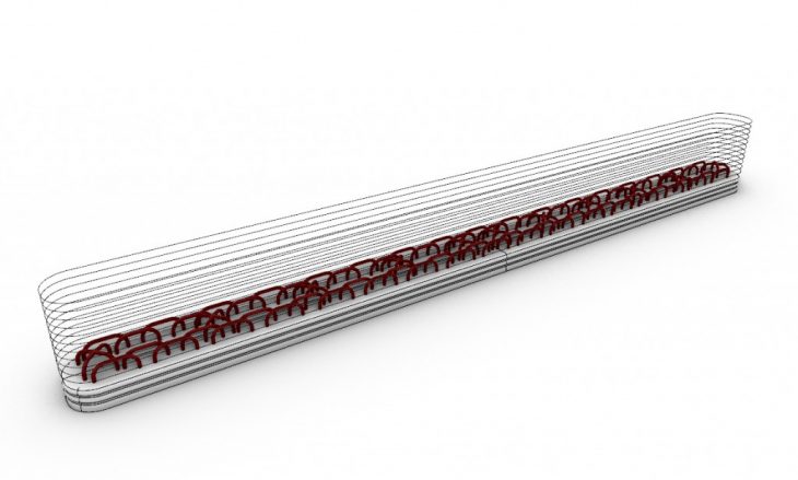
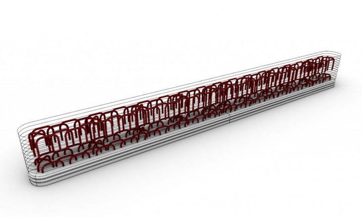
REINFORCEMENT : 1mm dia galvanized wire staple. Staple dimension 10mm x 10mm
CASE 1: UNREINFORCED BEAM. This will be the sample against which all other samples will be compared to.
CASE 2 : CONTINUOUS REINFORCED BEAM. This beam is designed as a standard beam with long continuous reinforcement in the bottom side of the beam below the neutral axis.

CASE 3 : STAPLE REINFORCED BEAM. This beam will have staple reinforcement added to the bottom half of the beam. The reinforcement is placed with 50% overlap along the longitudinal direction.
CASE 4 : STAPLE REINFORCED BEAM (TOP & BOTTOM) This geometry is designed to have staple reinforcement embedded in the top and bottom of the beam. The overap between saples will be 50%.
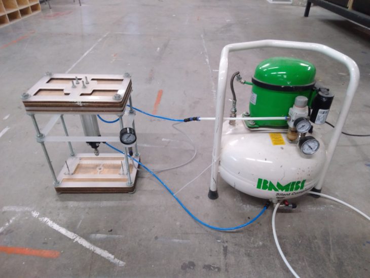
SETUP FOR LOAD TEST
The test set up comprises of a load test device that is attached to an air comressor. The compressor pumps compressed air that pushes the piston on the device to apply pressure on the test sample below it. The air pressure can be regulated by the researcher to achieve the desired pressure / load on to the sample.
TEST RESULTS:

CASE 1: UNREINFORCED BEAM.
The yeild / fracture point of an unreinforced concrete beam rsets up the base benchmark for the test that the reinforced beam has to overcome.
OBSERVATION : TOTAL FRACTURE
FRACTURE PRESSURE : 2.2 bar
: 31.9 psi
: 155 N of force applied by point with radius 15mm
CASE 2: CONTINUOUS REINFORCED BEAM.
The conventional beam reinforcement defines the optimum ratio of steel to concrete to tackle a predetermined amount of tensile stresses.
OBSERVATION : YIELD BUT NO FRACTURE
FRACTURE PRESSURE : 5 bar
: 72.5 psi
: 353.3 N of force
CASE 3: STAPLE REINFORCED BEAM.
OBSERVATION: YIELD AND DELAYED FRACTURE
FRACTURE PRESSURE : 2.4 bar
: 34..8 psi
: 169.6N of force
CASE 3: STAPLE REINFORCED BEAM. (TOP & BOTTOM)
OBSERVATION: YIELD BUT NO FRACTURE
FRACTURE PRESSURE : 2.5 bar
: 36.2 psi
: 176.42N of force
SIMULATION
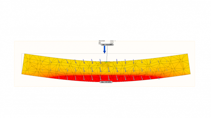
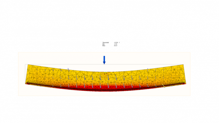
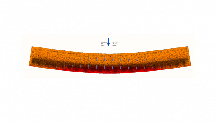
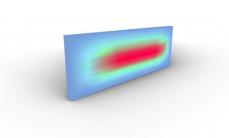
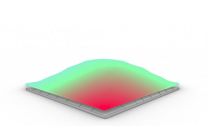
FINITE ANALYSIS ANALYSIS: The Finite Element Analysis (FEA) is the simulation of any given physical phenomenon using the numerical technique called Finite Element Method (FEM). To be able to simulatethe behaviour of an element under specific conditions, it is divided into millions of small elements that together form the shape of the structure needs to be created. Calculations are made for every single element. Combining the individual results gives us the final result of the structure. The approximations we just mentioned are usually polynomial and in fact, interpolations over the element(s). This means we know values at certain points within the element but not at every point. These ‘certain points’ are called nodal points and are often located at the boundary of the element. A F.E. Analysis is done on the same conditions as the test to check for accuracy and to train future models.
1ST PRINCIPAL STRESS: The 1st principal stress gives you the value of stress that is normal to the plane in which the shear stress is zero. The 1st principal stress helps you understand the maximum tensile stress induced in the part due to the loading conditions.
3RD PRINCIPAL STRESS: The 3rd principal stress acts normal to the plane in which shear stress is zero. It helps you understand the maximum compressive stress induced in the part due to the loading conditions.
SIMULATION TEST
CASE 1 : UNREINFORCED BEAM
MATERIAL: CONCRETE
GEOMETRY : 16MM X 242MM X 30MM HT BEAM
LOAD CONDITIONS : 120 N POINT LOAD
SUPPORT CONDITIONS : SIMPLY SUPPORTED BEAM
CASE 2 : CONTINUOUS REINFORCED BEAM
MATERIAL: CONCRETE
1MM DIA GALVANISED STEEL WIRE STAPLES.
CONTINUOUS WIRE 240 MM L
GEOMETRY : 16MM X 242MM X 30MM HT BEAM
LOAD CONDITIONS : 120 N POINT LOAD
SUPPORT CONDITIONS : SIMPLY SUPPORTED BEAM
CASE 3 : STAPLE REINFORCED BEAM
MATERIAL: CONCRETE
1MM DIA GALVANISED STEEL WIRE STAPLES.
STAPLE SIZE : 10MM X 10MM
GEOMETRY : 16MM X 242MM X 30MM HT BEAM
LOAD CONDITIONS : 120 N POINT LOAD
SUPPORT CONDITIONS : SIMPLY SUPPORTED BEAM
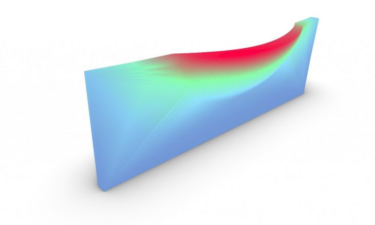
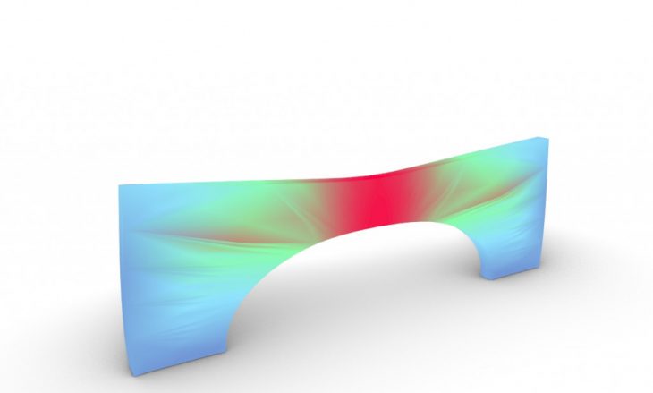
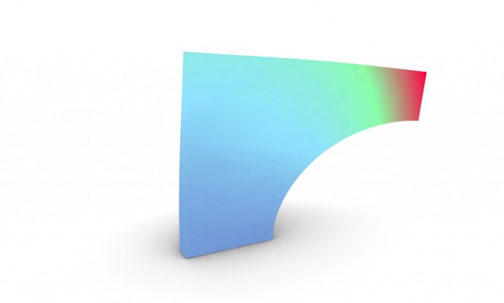
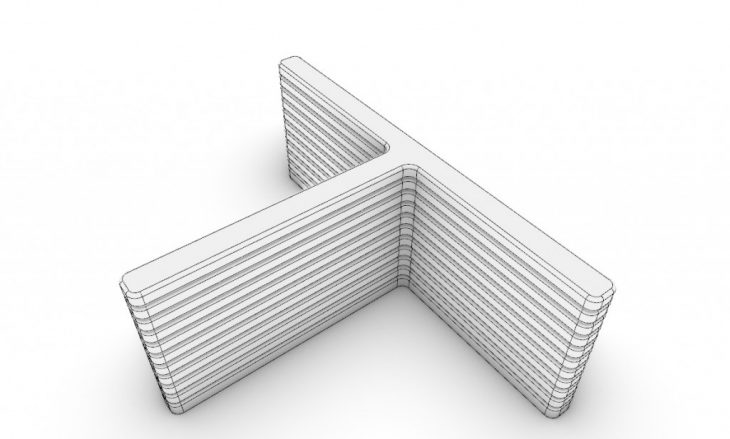
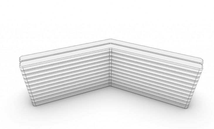
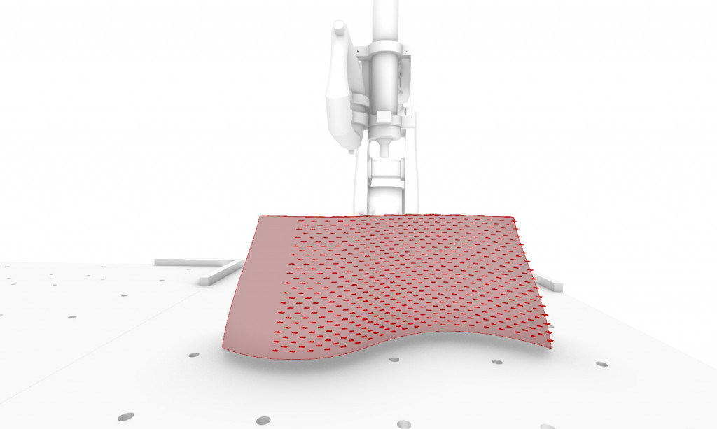
GEOMETRY TYPOLOGY
Based on the results of the simulation, different geometries can be evaluated using F.E. Analysis to determine key stress areas and the reinforcement can be applied strategically to resolve them. The advantage of the staple lies in its ability to tackle locally developed stresses, thereby minimizing the need overload the structure.
VERTICAL EXTRUSIONS:
ORTHOGONAL EXTRUSION ALONG XYZ AXIS:
ORTHOGONAL EXTRUSION WIITH DEVIATION ALONG XY AXIS
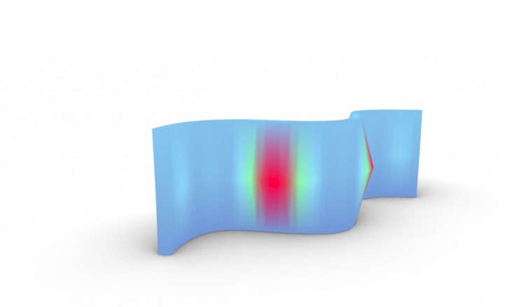
ORTHOGONAL EXTRUSION WIITH DEVIATION ALONG XYZ AXIS
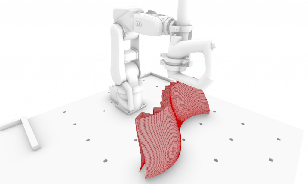
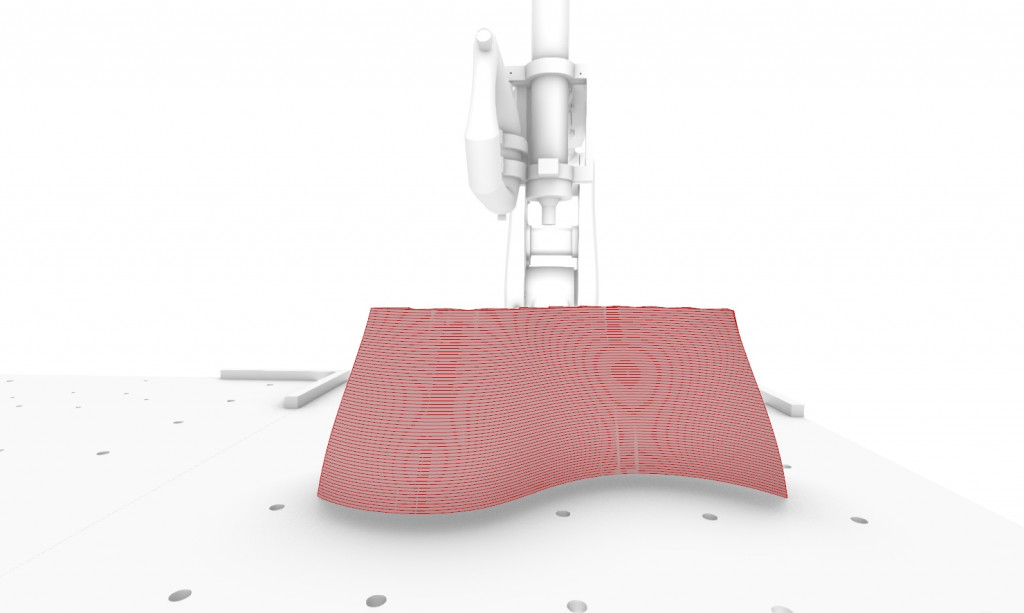
SPANS:
ARCH OPENING:
CANTILEVER:
SHELL:
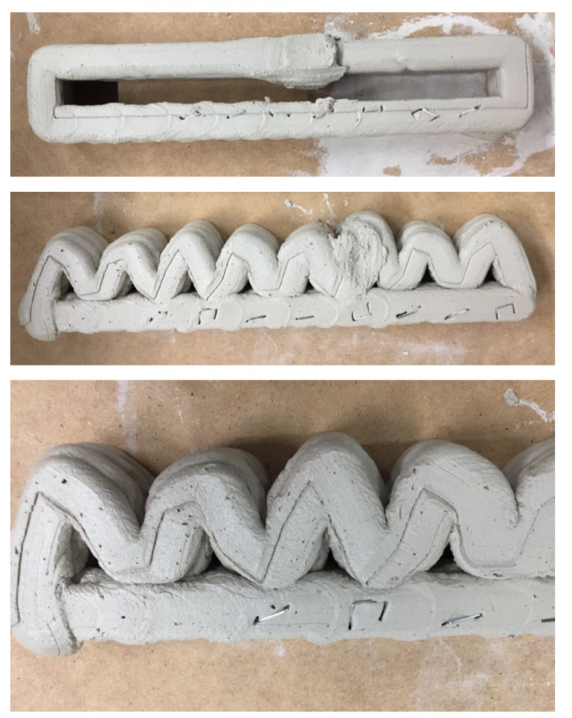
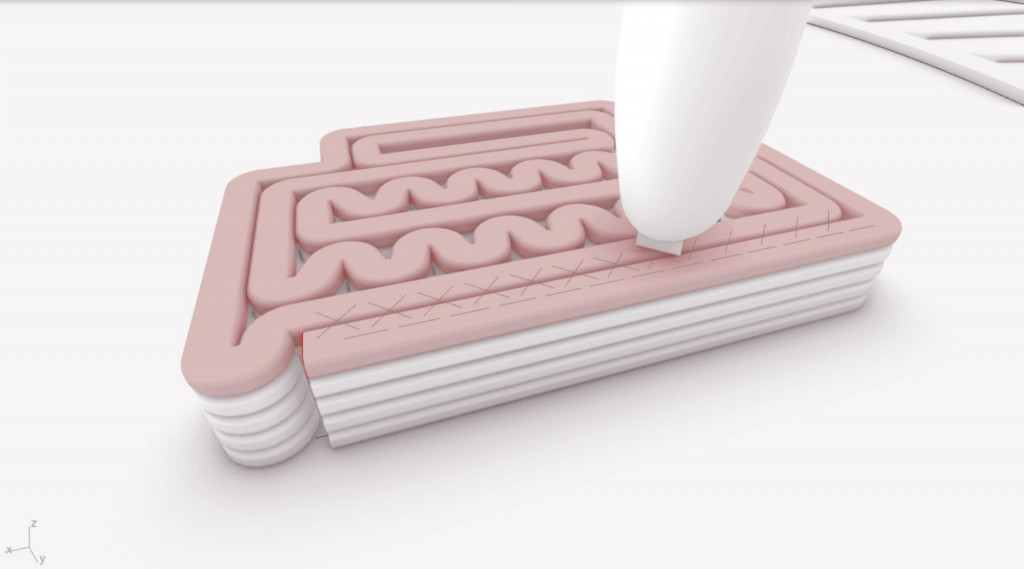
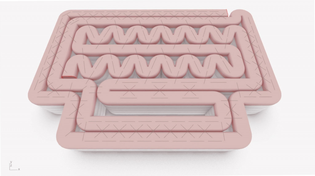
PRINT & REINFORCEMENT STRATEGY:
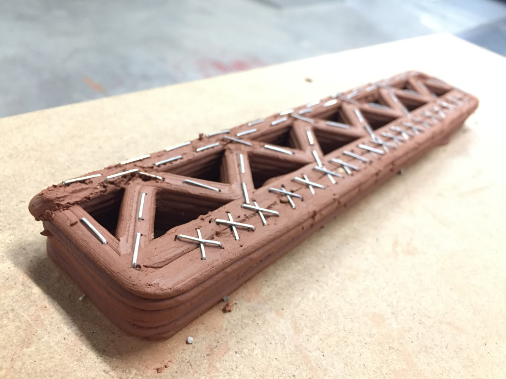
Print parameters such as nozzle thickness, toolpath and layer thickness determine the resolution of geometry into a viable model that can be printed using an extruder. The reinforcement strategy can be used not only to enhance layer to layer binding but also strengthen weak corners. Parallel lyer can be strengthened by the use of cross reinforcement that may unify both parts to act as a single element.
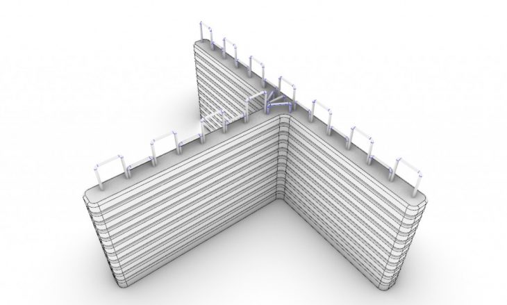

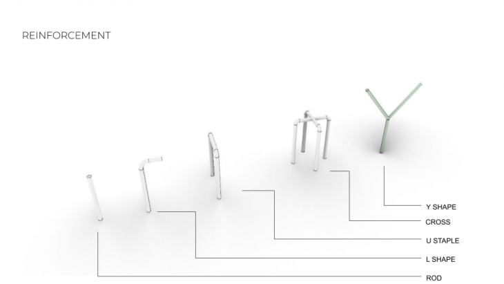
REINFORCEMENT TYPES
As geometry gets complicated, the standard staple might be insufficient to tackle ll the problems faced by the geometry and the print. In such cases different types of reinforcement adept at tackling unique problems meed to be developed to address these issues.
A final print can therefore be envisioned as a combination of different types of staples, each designed to tackle a specific situation at a specific location in the geometry.
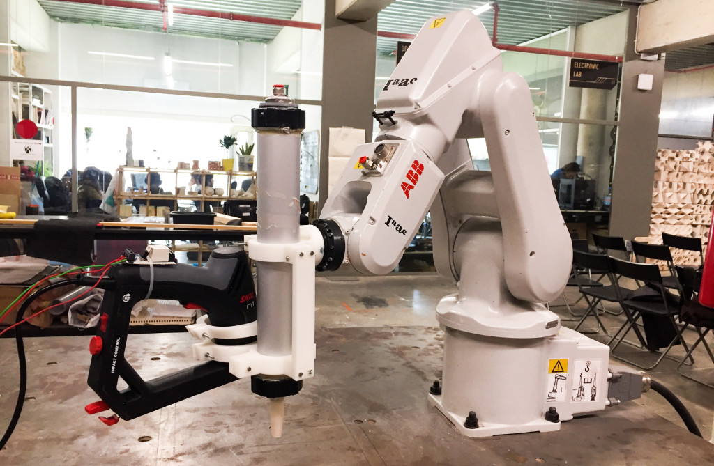
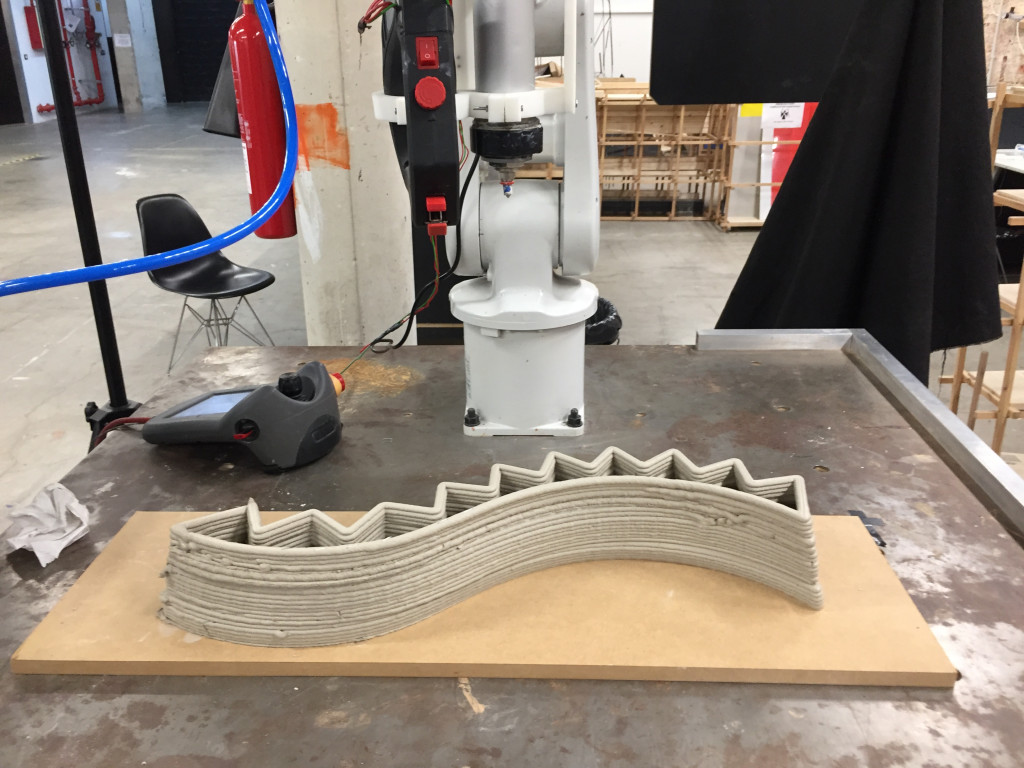
TOOL DEVELOPMENT
When it came to designing the stapling hardware, we had two goals in mind.
1.Designing a tool that is able to print & staple simultaneously at the same time
2.Being able to realize a wide range of stapling configuration flexibly using the tool
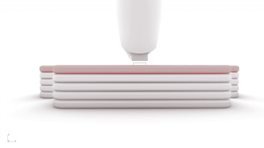
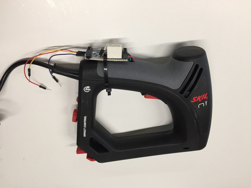
We purchased an industrial electrical staple gun. We hacked the gun; we first removed the safety switch, then we replaced the triggering button with a relay that can be controlled by a 24V signal. The end result was a stapling gun that can firs staples at a given signal without having to be pressed against any material (safety switch)
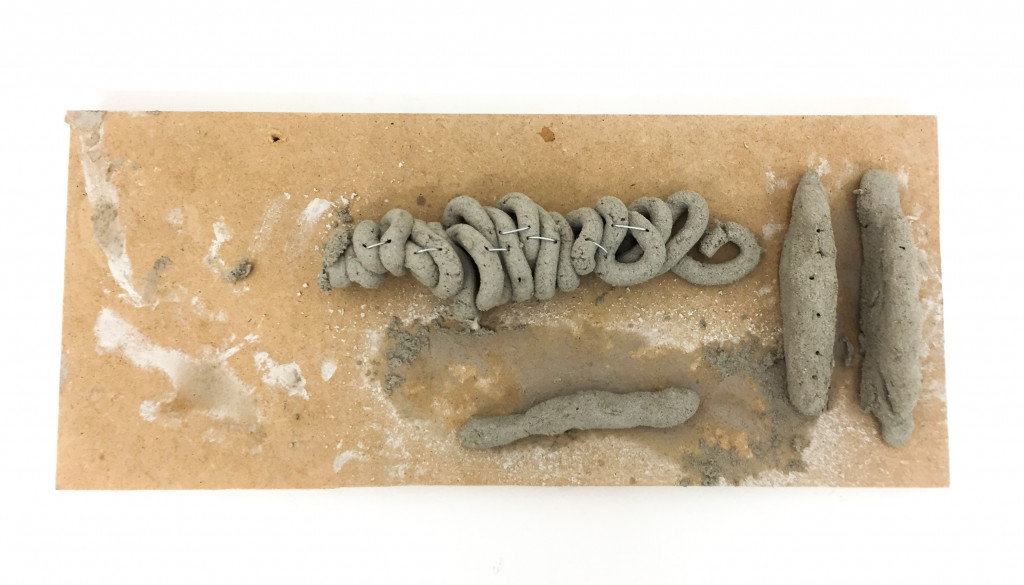
First Round of Testing
SETUP USED:
- Print : Manually
- Stapling: Manually
TRIALS GOALS
- Testing out stapling
- Understanding the material behaviour
In the early trials conducted, the goal was to understand the correct way to staple given the material behavior of the print. In the early versions of our vision, we imaged stapling to happen first with staples being not fully immersed half way through the print. Then printing over it and letting the printing material surround the staple from all directions for better bonding. Something that proved being unpractical; it was observed that due to the high viscosity of the material, it does not fill the areas around the staples correctly. Accordingly, a better approach would be to staple after a layer is printed and immersing the staple all the way through to connect with the layers beneath.
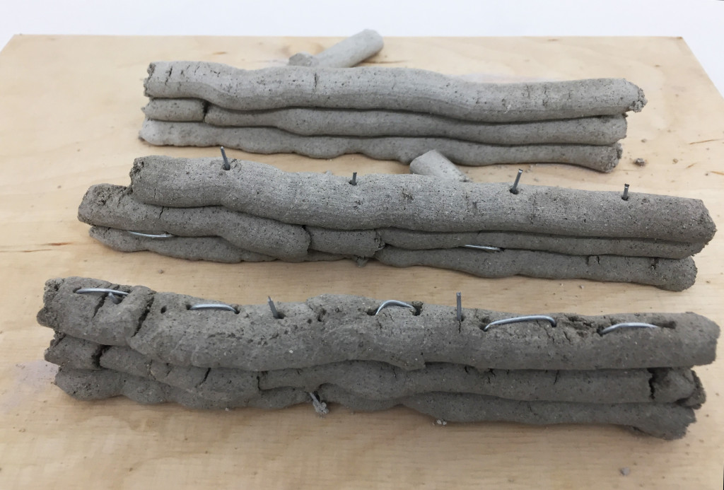
Second Round of Testing
SETUP USED
- Print : Robot
- Stapling: Staple gun
TRIALS GOALS
- Testing out the hardware tool
- Tunning the required pressure for stapling
Following that, the goal was to fine tune the correct way to staple using thestapling gun we hacked previously. The conclusion of these experiments were first that changing the impact factor of stapling pressure didn’t affect the stapling result very much. Due to “U” shape of the staples they are always stopped correctly at the surface of the layer. However, it is always better to staple with the least pressure possible to prevent ruining the structure with the high pressure from the stapling hardware. The second observation was that the layer height should be as low as possible for better connectivity between layers using the staples.
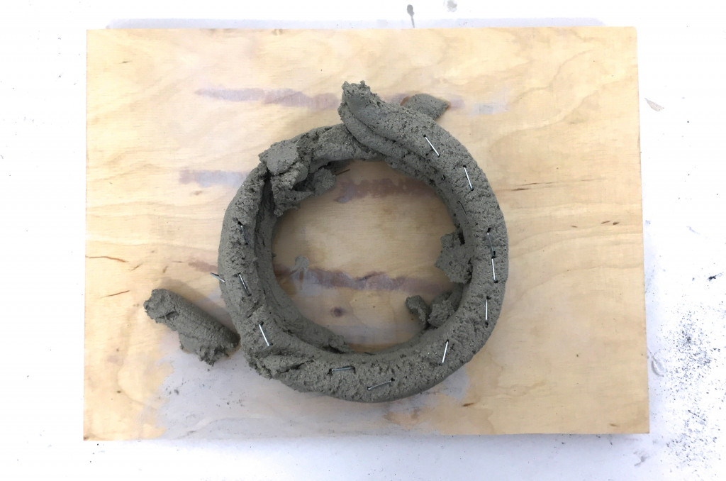
Third Round of Testing
SETUP USED
- Print : Robot
- Stapling: Staple gun + Robot
TRIALS GOALS
- Using the robot to print and staple
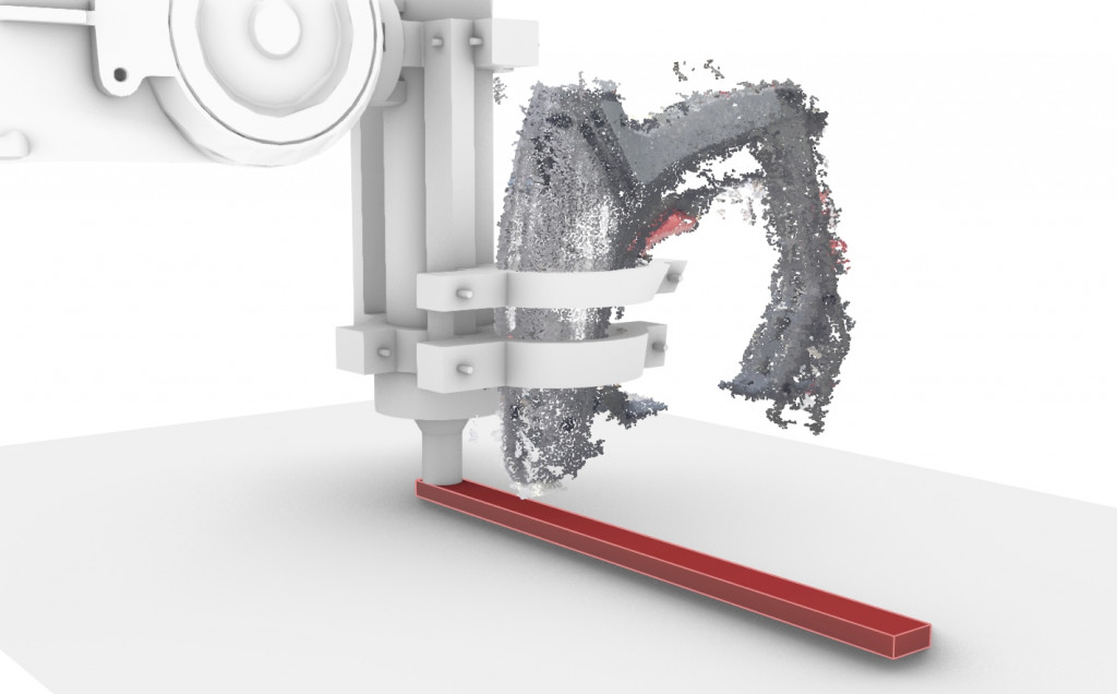
This test was the first exploration in stapling automatically using the robot using a code that links printing with stapling in the designated areas. The obvious observation in the experiment was that stapling was not accurate due to the high distance between the stapling hardware’s TCP and the surface of the print. This distance resulted in some of the staples to be fired at an angle which lead to a poor stapling quality. Something that can be solved by having the stapling gun mounted as close to the printed layers as possible.
Fourth Round of Testing
SETUP USED
- Print : Robot
- Stapling: Staple gun + Robot
TRIALS GOALS
- Feeding reinforcement from simulation software
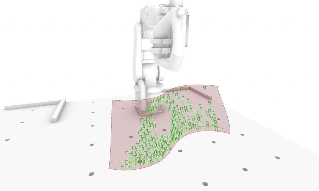
The next step was to explore feeding a reinforcement strategy driven from a structural simulation software to staple a reinforcement only where requi- red. The process started by dividing the geometry into voxels depending on the available constrains; print layer height, staple dimensions & stapling hardware limitations. These cell divisions where later used in the structural simulation to decide whether a reinforcement was required at a certain cell or not.
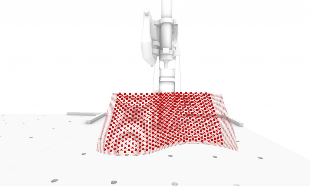
The next step was to explore feeding a reinforcement strategy driven from a structural simulation software to staple a reinforcement only where required. The process started by dividing the geometry into voxels depending on the available constrains; print layer height, staple dimensions & stapling hardware limitations. These cell divisions where later used in the structural simulation to decide whether a reinforcement was required at a certain cell or not.
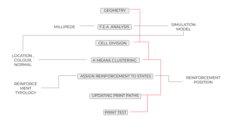
MACHINE LEARNING
The process of evaluting a geometry to identify the key stress areas when cted upon by specific load conditions to identfying the type of reinforcement for each state to developing a strategy for print is a process that can be simplified if it can be automated using maching learning algorithms.
Different machine learning strategies like building a neural network can be developed to assign and optimize different types of reinforcement to different areas of the geometry thereby outputting the most optimum solution which utilises the reinforcement sparsely.
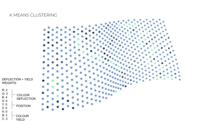
Another type of unsupervised learning called the k-means clustering can be used to group different states / regions of the geometry based on weightage and thus assign a specific type of reinforcement to it.
K – MEANS CLUSTERING
K-means clustering is a simple unsupervised learning algorithm that is used to solve clustering problems. It follows a simple procedure of classifying a given data set into a number of clusters, defined by the letter “k,” which is fixed beforehand. The clusters are then positioned as points and all observations or data points are associated with the nearest cluster, computed, adjusted and then the process starts over using the new adjustments until a desired result is reached. It aims to partition a set of observations into a number of clusters (k), resulting in the partitioning of the data into Voronoi cells. It can be considered a method of finding out which group a certain object really belongs to.

Linking with printing code
The observations from this trial was that the layer width needed to be wider for more accurate stapling. The other conclusion was that setup for tool mounting is maybe imposing a lot of constrains that could stand in the way of having a wider range of more effective stapling strategies. Something that is explained in detail in the next section.
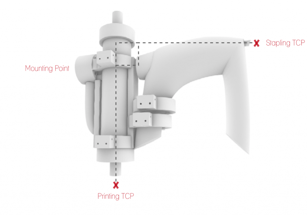
TOOL MOUNTING SETUP
FIRST SETUP
So far the used mounting setup of the tool had the stapling TCP behind the Printing TCP. This helped in having a seamless simultaneous process of printing and stapling. Yet, it imposed restricting limitations in the type of reinforcement strategy possible to be realized.
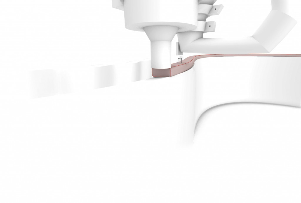
Stapling TCP behind Printing TCP
As shown in the following image where the printing TCP indicated as a circle and the stapling TCP indicated as a cross point. If the tool path were to follow the normal movement in most of the 3D printing application. Thestapling will always occur outside of the layer boundaries. For that printingframe has to be always oriented in a way that allow of the stapling to occur in the correct place. But, even when you switch to a tangential movement where the tool is oriented to the tangent of the curve at any given time. It would still staple outside of the layer most of the time. So the solution was to constantly project the stapling TCP to the print path and orient the printing plane yo the vector connecting the printing TCP to the project point. By that, its always ensured that tool is oriented at the correct orientation at any given time.
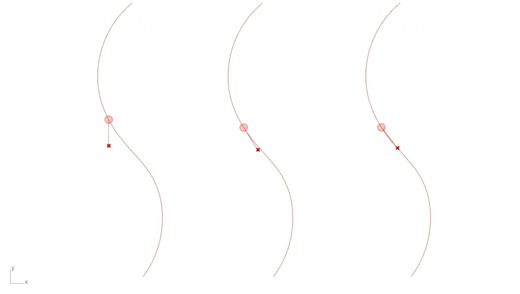
Normal 3D Print Path | Tangential Movement | Projected Movement
This solution however imposes certain limitations on the tool that restricts the stapling strategies that can be realized.
- The print path’s curvature is restricted by the distance between the nozzle and the staple hardware.
- Stapling happens in a unidirectional way, its difficult to print in the return path.
- At the begining of each layer there is this blind spot where stapling can’t happen due to the distance between the printing nozzle and the stapling hardware.
So by analyzing these factors against the initial hardware tool design goals. It will be evident that this setup is achieving the first goal effectively. But isn’t as effective in the second one.
SECOND SETUP
Another solution for addressing these constrains would be to have the stapling TCP perpendicular to the printing TCP. And printing would occur first, printing the first “n” of layers (depending on the staple depth) then pausing the print, rotating the tool 90 degrees, and start stapling the reinfor- cement. The whole process would be repeated over and over again until the print is over.
This set up adds a lot of freedom in possible reinforcement configurations. And opens up the space for new types of reinforcement; like being able to have overlapping staples, cross bracing, connecting infills with external layers & being able to fire staples at an angle.
Yet, it separates printing from stapling making the overall process less simultaneous compared to the previous setup.
Fifth Round of Testing
SETUP USED
- Print : Robot
- Stapling: Manually
TRIALS GOALS
- Separating printing and stapling
- Testing having an overlapping staples
In order to test out the 2nd tool mounting setup. This test was conducted with the aim of trying to test out the possibility of stapling overlapping staples. In this trial, printing and stapling were separated; each five layers the printing was paused to manually insert 50 overlapping staples. The print had a total of 15 layers with 3 reinforced layers making a total of 150 staples per piece.
Sixth Round of Testing
SETUP USED
- Print : Robot
- Stapling: Staple gun + Robot
- Staple Approach: 2nd
TRIALS GOALS
- Having more flexibility in staple stratgies
Using the data driven from the last experiment. With then designed a beam-like structure with infills inside it. We printed it using the robot and used a reinforcement strategy which involved cross bracing, connecting the double offset of the outer layers & connecting infill with the outer layers. The 2nd mounting approach seemed to be more effective and practical in realizing different strategies. It also showed improved accuracy in the stapling process.
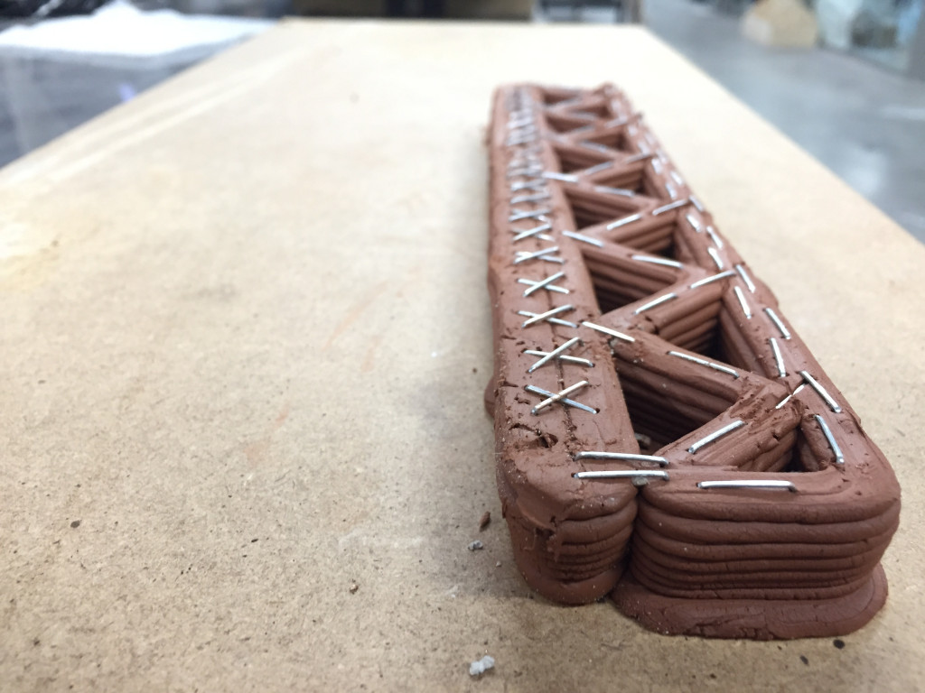
———————-
BIBLIOGRAPHY
Aghaei Meibodi, Mania, Mathias Bernhard, Andrei Jipa, and Benjamin Dillenburger. 2017. “The Smart Takes from the Strong 3d Printing Stay-in-Place Formwork for Concrete Slab Construction.” In Fabricate 2014: Negotiating Design & Making, 210–17.
Alothman, Sulaiman, Hyeonji Claire Im, Francisco Jung, and Martin Bechthold. n.d. “Spatial Print Trajectory Controlling Material Behavior with Print Speed , Feed Rate , and Complex Print Path.” In .
Freek P. Bos, Zeeshan Y. Ahmed, Rob J.M. Wolfs, and Theo A.M. Salet “3D Printing Concrete with Reinforcement” Department of the Built Environment, Eindhoven University of Technology,
P.O. Box 513, 5600 Eindhoven, MB, The Netherlands
Freek P. Bos, Theo A.M. Salet, Emanuela Bosco “Ductility of 3D printed concrete reinforced with short straight steel fibers” Article in Virtual and Physical Prototyping · November 2018
Battaglia, Christopher A., Martin Fields Miller, and Sasa Zivkovic. 2018. “Sub-Additive 3D Printing of Optimized Double Curved Concrete Lattice Structures.” In Robotic Fabrication in Architecture, Art and Design 2018, 242–55. doi:10.1007/978-3-319-92294-2_19.
Bhooshan, Shajay, Johannes Ladinig, Tom Van Mele, and Philippe Block. 2019. “Function Representation for Robotic 3D Printed Concrete.” In Robotic Fabrication in Architecture, Art and Design 2018, 98–109. doi:10.1007/978-3-319-92294-2_8.
Dubor, Alexandre, Jean-Baptiste Izard, Edouard Cabay, Aldo Sollazzo, Areti Markopoulou, and Mariola Rodriguez. 2018. “On-Site Robotics for Sustainable Construction.” In Robotic Fabrication in Architecture, Art and Design 2018, 390–401. doi:10.1007/978-3-319-92294-2_30.
Friedman, Jared, Heamin Kim, and Olga Mesa. 2014. “Experiments in Additive Clay Depositions.” Robotic Fabrication in Architecture, Art and Design 2014, no. 2012: 261–73. doi:10.1007/978-3-319-04663-1.
Gardiner, James B, and Steven R Janssen. 2014. “Development of a Construction-Scale Robotic Formwork 3D Printer.” In Robotic Fabrication in Architecture, Art and Design 2014, 131–46. doi:10.1007/978-3-319-04663-1.
Gaudilli, Nadja, Romain Duballet, and Charles Bouyssou. 2019. “Large-Scale Additive Manufacturing of Ultra-High-Performance Concrete of Integrated Formwork for Truss-Shaped Pillars.” In Robotic Fabrication in Architecture, Art and Design 2018. Vol. 2.
GLYNN, RUAIRI, BOB SHEIL, and XAVIER DE KESTELIER. 2019. “Design Potential for Large-Scale Additive Fabrication.” In Fabricate 2011, 243–49. doi:10.2307/j.ctt1tp3c6d.45.
Hack, Norman. 2015. “Mesh Mould?: Robotically Fabricated Metal Meshes as Concrete Formwork and Reinforcement MESH MOULD?: ROBOTICALLY FABRICATED METAL MESHES AS.” In .
Huang, Yijiang, Josephine Carstensen, and Lavender Tessmer. 2019. “Robotic Extrusion of Architectural Structures with Nonstandard Topology.” In Robotic Fabrication in Architecture, Art and Design 2018.
Ko, Minjae, Donghan Shin, Hyunguk Ahn, and Hyungwoo Park. 2019. “InFormed Ceramics: Multi-Axis Clay 3D Printing on Freeform Molds.” In Robotic Fabrication in Architecture, Art and Design 2018, 297–308. doi:10.1007/978-3-319-92294-2_23.
Søndergaard, Asbjørn, Jelle Feringa, Florin Stan, and Dana Maier. 2019. “Realization of Topology Optimized Concrete Structures Using Robotic Abrasive Wire-Cutting of Expanded Polystyrene Formwork.” In Robotic Fabrication in Architecture, Art and Design 2018, 473–88. doi:10.1007/978-3-319-92294-2_36.
Yuan, Philip F, Hao Meng, Lei Yu, and Liming Zhang. 2016. “Robotic Multi-Dimensional Printing Based on Structural Performance.” In Robotic Fabrication in Architecture, Art and Design 2016. doi:10.1007/978-3-319-26378-6.
SIMULTANEOUS REINFORCEMENT OF CONCRETE WHILE 3D PRINTING is a project of IaaC, Institute for Advanced Architecture of Catalonia developed at MRAC, Masters of Robotics and Advanced Construction in 2019 by:
Students: Omar Geneidy | Sujay Kumarji
?Faculty: Alexandre Dubor | Aldo Sollazzo
?Mentors: Kunaljit Chadha | Eugenio Bettucchi | Raimund Krenmueller | Starsky Lara