ORIGINAL CONFIGURATION 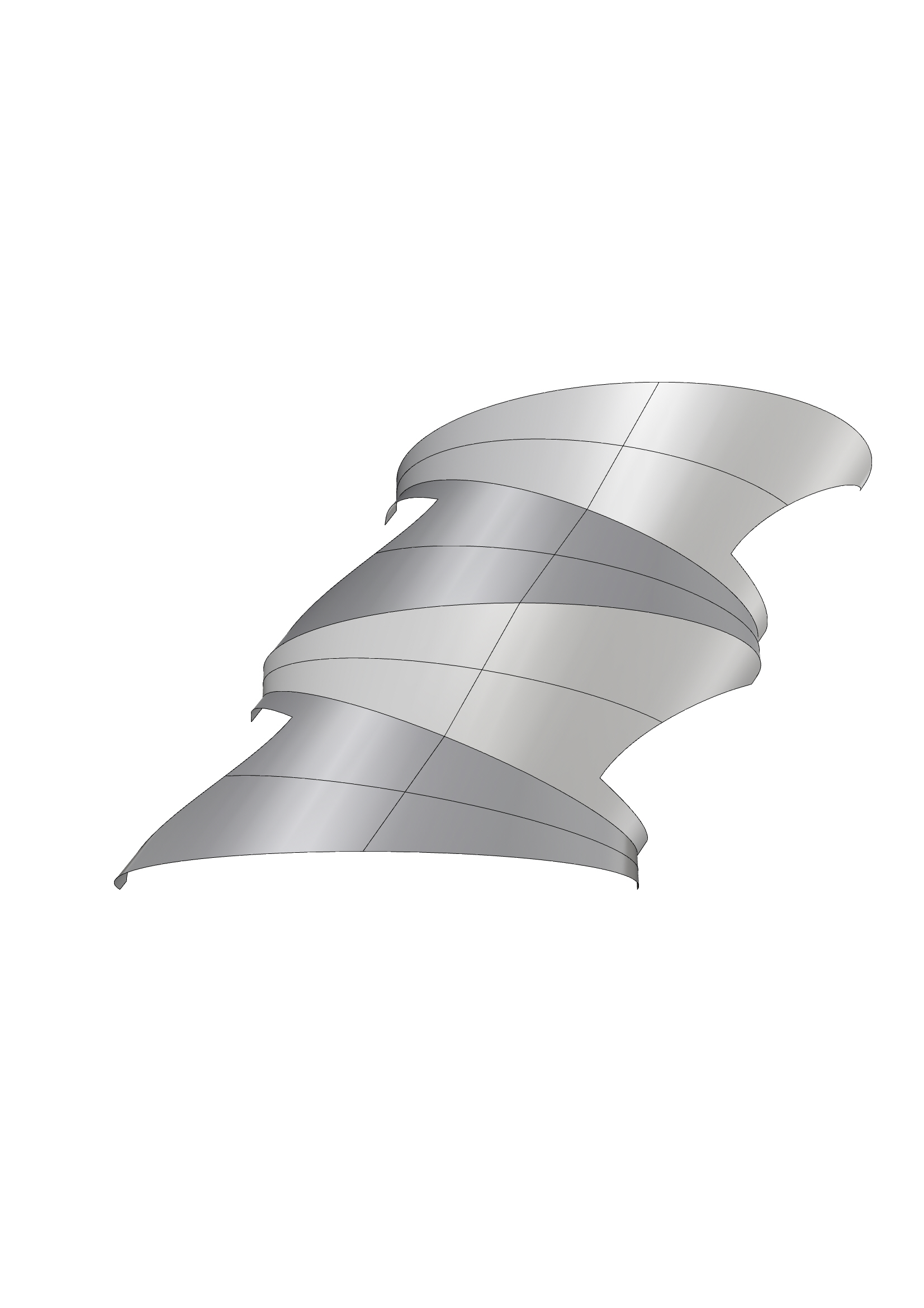
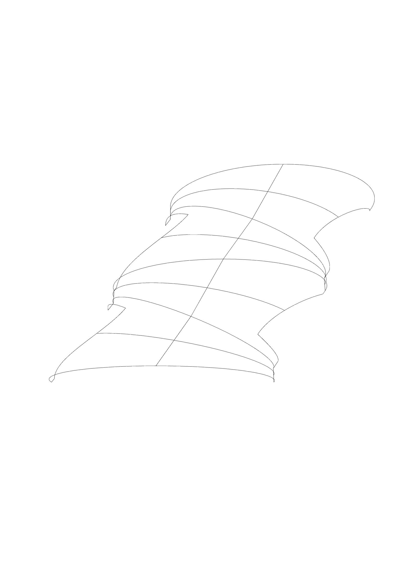 Our base structure was arches joined in a zip-way. We created a surface between and got a vault structure in case of better understanding of structural behavior. SELF LOAD-FIXED SUPPORTS

 SELF LOAD-PINNED SUPPORTS

 1 APEX PT LOAD-FIXED SUPPORTS

 1 CENTRAL PT LOAD-FIXED SUPPORTS

 1 APEX PT LOAD-PINNED SUPPORTS

 1 CENTRAL PT LOAD-PINNED SUPPORT

 Displacement: Looking at the displacement grafs we can see where is structure’s deformation affected by load. In the diagrams we can understand that the deformations of the structure are not only in the place where the load is placed, but also in places of arches tension according to supports. Stress Vector: The stress vector lines show the movement of forces between the load and supports. In the diagrams we can see that the stress lines gradually spreaded from the load to sopports and the most tension achieve closer to supports. Utilization: It shows the performance of the material. Looking at the diagrams we can see that material work in the placement of load and closer to supports. CHANGED SUPPORTS SELF SUPPORTED-FIXED SUPPORTS

 SELF SUPPORTED-PINNED SUPPORTS

 Understanding of structural behavior by changing of supports place: In diagrams you can see that moving the supports in different axes the most tension of structure is always closer to the base points of supports.