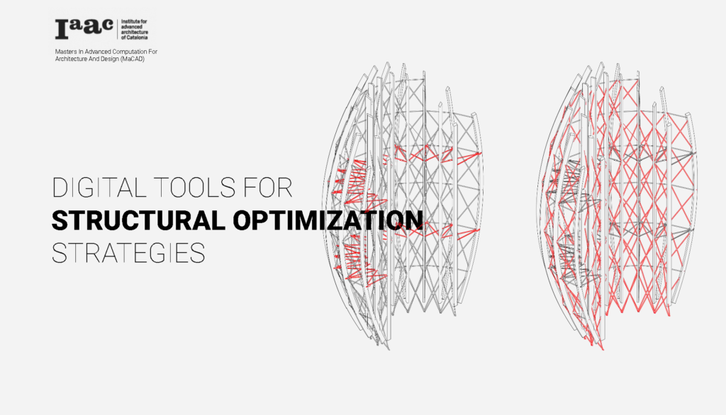
+ ABSTRACT
Restore and Reconnect Western Sydney is a project that focuses and how to reprogram and activate an unused toxic environment within the center of the city of Sydney. It has two main components to achieve the objectives: a bridge that interconnects the site and a series of Wind reactive towers that can activate a rewilding component in the area. In this project we were setting up, evaluating, and optimizing the structural system of both of the project elements, the tower, and the bridge.
+ MASTERPLAN // Garden towers

The case study for this structural analysis has two main structural typologies: Bridges and Towers. In this study, both cases are analyzed separately.
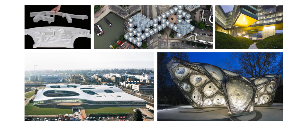
+ THE BRIDGE // Precedent study
+ THE BRIDGE // Design Concept
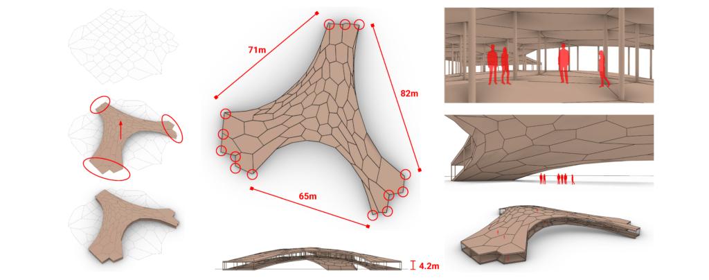
The bridge structure has a vault form and is generated from a 2D Voronoi pattern using a catenary form-finding method. The structure is only supported at the edges, where the vault meets the ground, which allows for the largest possible span of around 82m.
+ THE BRIDGE // Setting up the loads
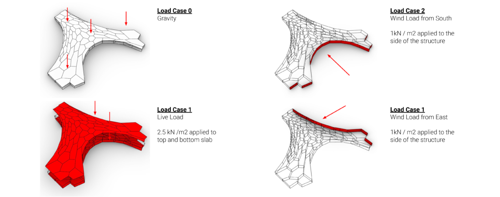
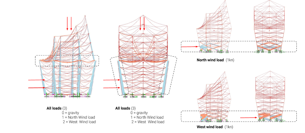
For this structural study, four load cases are applied to the structure: gravity, wind loads, and live loads. wind loads from east and south with 1 kN/m2 values are taken into consideration in the analysis. 2.5 kN Live loads are given to the top and bottom surface as the structure is expected to be trafficable internally and externally.
+ THE BRIDGE // Structural options
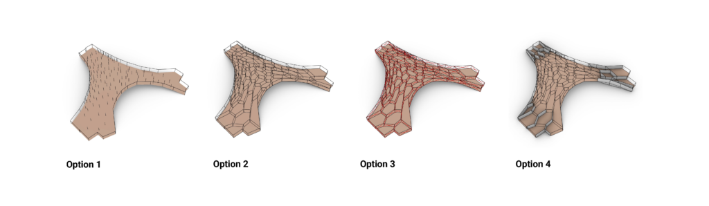
Four options are generated in this study, the evolution of the structures will be explained in the following sections
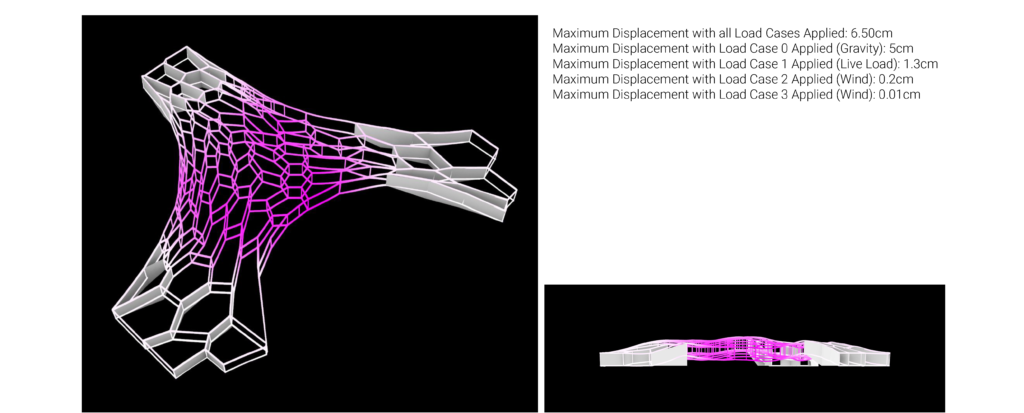
+ THE BRIDGE // Concrete Shell + Timber Column
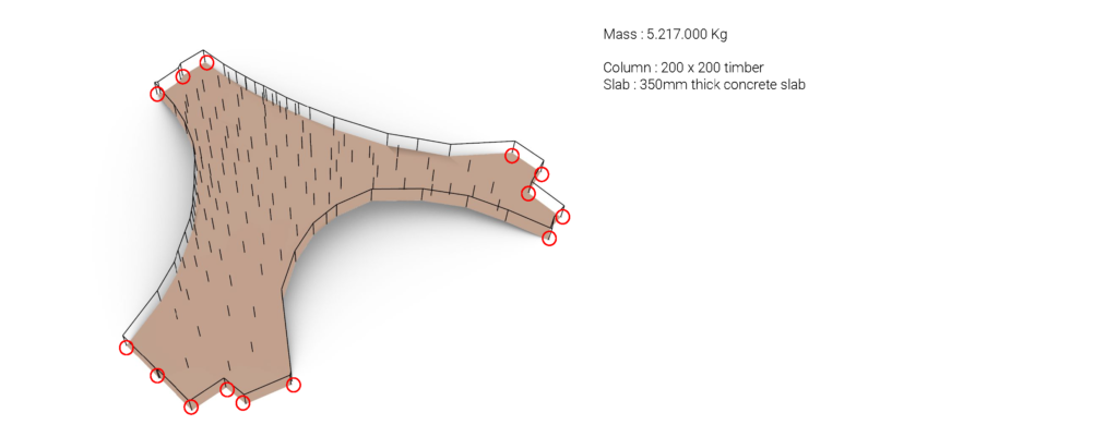
In this first option, the structure only consists of columns and shells ( top and bottom floor ). The column uses 200 x 200 timber and the slab uses 350mm thick concrete. The structure’s weight is about around 5.217.000 Kg
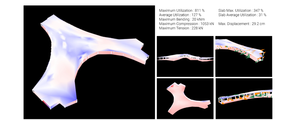
It can be seen from the diagram that the structure is not performing very well. There is a huge bending moment near the support and the structure seems to struggle to carry its own self-weight.
+ THE BRIDGE // Timber space frame
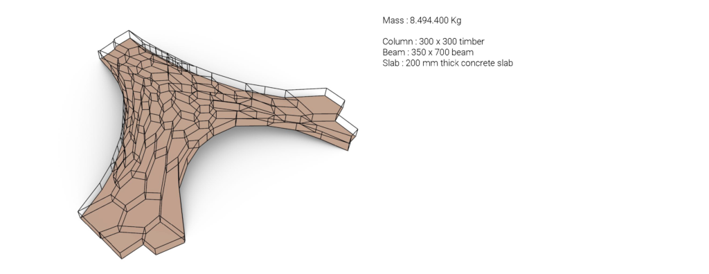
In this 2nd iteration, beams are introduced at every edge of organic patterns generated earlier. The idea is to make the entire structure work as a habitable space frame. The structure weighs about 8.494.400 Kg, much heavier than the previous option due to the addition of structural beams.
Even though there is a slight improvement, there is still a huge bending moment near the support. Other than these problematic members, The rest of the structural members seem to be larger than it requires, making the structure quite inefficient.
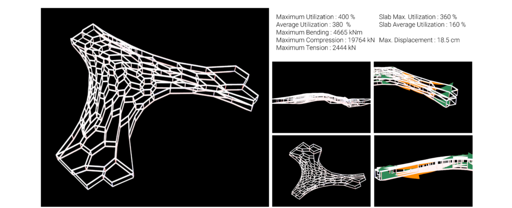
+ THE BRIDGE // Timber space frame + Bracing
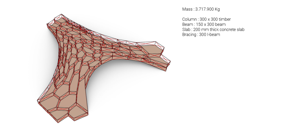
To solve the problem that occurred in the previous two options, bracing is introduced and joints are released to minimize bending. Even though many new members are added, the structure is less heavy (3.717.900 Kg) than the previous one due to the reduction of the main structural beam size.

It can be seen from the diagram that huge bending moments are successfully reduced, but the members near the support are still carrying too many loads compared to the rest of the members. However, there is a great improvement from the previous options.
+ THE BRIDGE // Timber space frame + shear wall
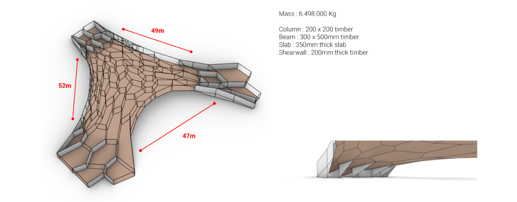
Since in the previous options, most of the problems are occurring in the members near the support. These members are enforced by shear walls in this 4th option. These shear walls are also extended to the ground, reducing the span between support to 52m maximum.
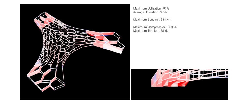
From the analysis, this option is more feasible than other options as its utilization doesn’t exceed 100%. Due to the reduction of the span and the introduction of the shear wall near the support, there is a great improvement in the structural capability.
However, it still has a high value of global displacement, which is also caused by its own self-weight. So there still needs to be a further exploration in the future to improve the structural performance.
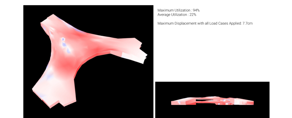
The 350mm thick slab is also working quite well considering its span. There is still potential improvement to reduce the thickness and the self-weight.
+ THE BRIDGE // Load Distribution
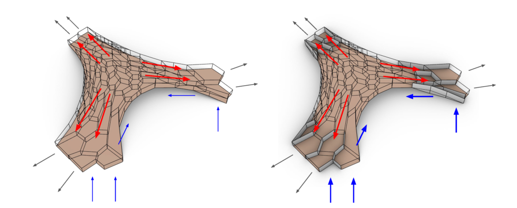
As the structure is only supported near the anchor, the fourth option performs very well due to high reinforcement at the area where the loads are concentrated. These shear walls also help the vault structure from flattening, and tie beams are potentially introduced.
However, the rest of the members might also need to be reinforced by bracing or other strategies to reduce displacement and self-weight.
+ THE BRIDGE // Summary
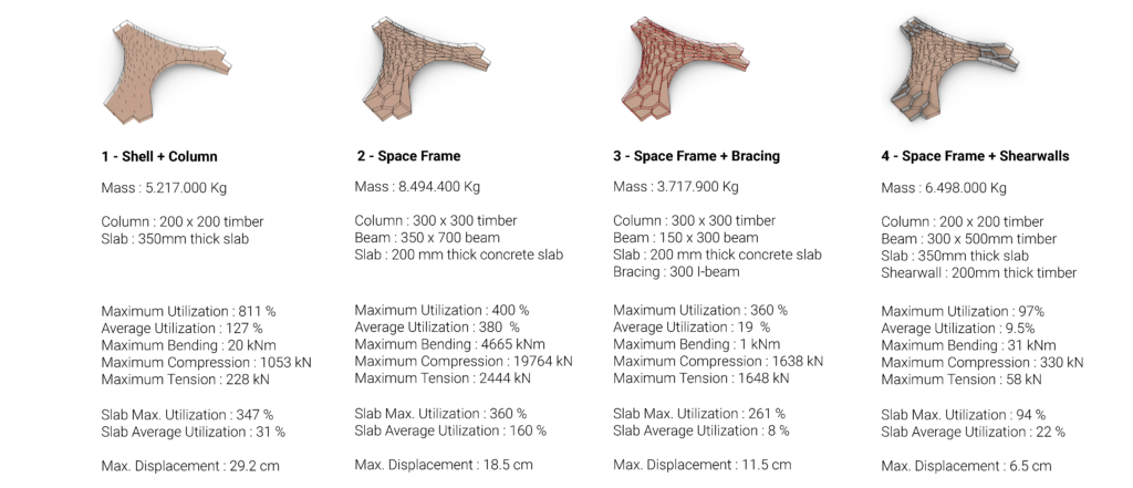
It can be concluded that the 4th option is the best, compared to the rest of the options, however further exploration is still yet to be taken.
+ THE TOWER // Case Study
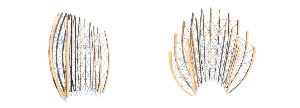
The Jean-Marie Tjibaou Cultural Center structure.
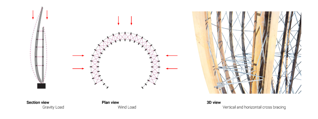
Vertical and lateral force path.
+ THE TOWER // Form setup
The first step is setting up the structural analysis models. This is done by running a genetic optimization of the form in an attempt to maximize shading below the structure.
+ THE TOWER // Parameter and structure setup
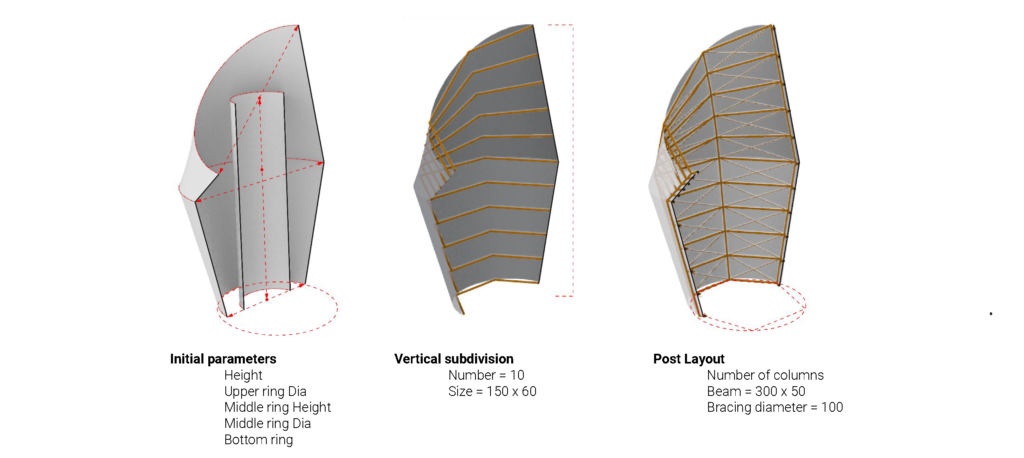
Setting up the parameters of the optimization.
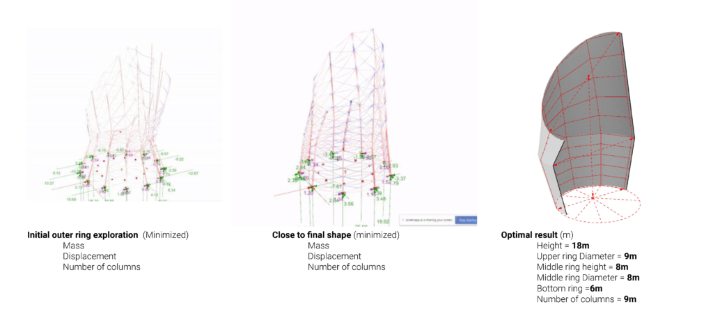
Initial pattern optimization to get the optimal form.
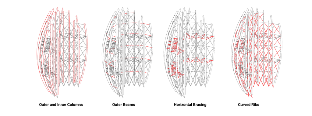
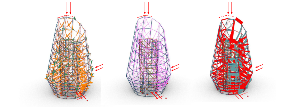
+ THE TOWER // Structural Behavior
+ INNER CORE // Reinforcement
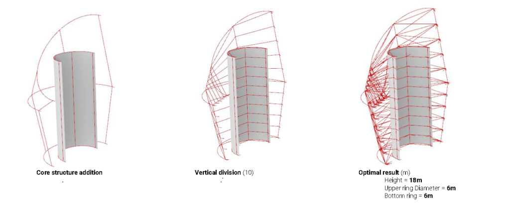
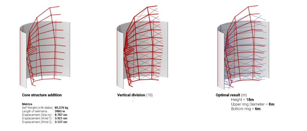
A core has been added in the center of the structure and is braced to the exterior frame.
+ INNER CORE // Bracing optimization
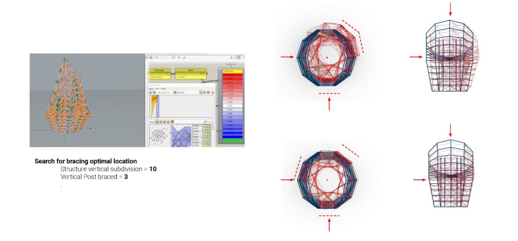
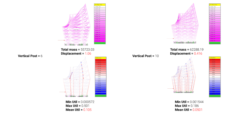
The placement of the bracing is done through genetic optimization. A Vertical post bracing of 3 and is subdivided into 10 divisions.
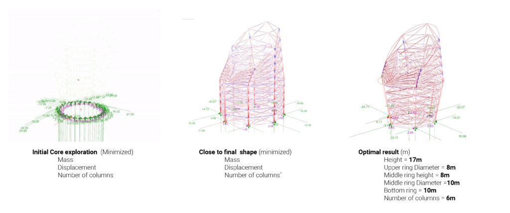
+ INNER CORE // Optimal form
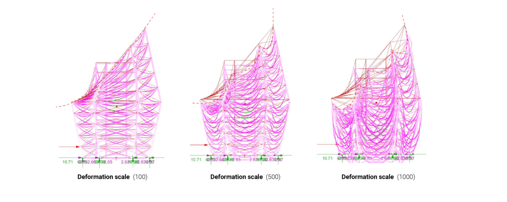
+ INNER CORE // Deformation Analysis
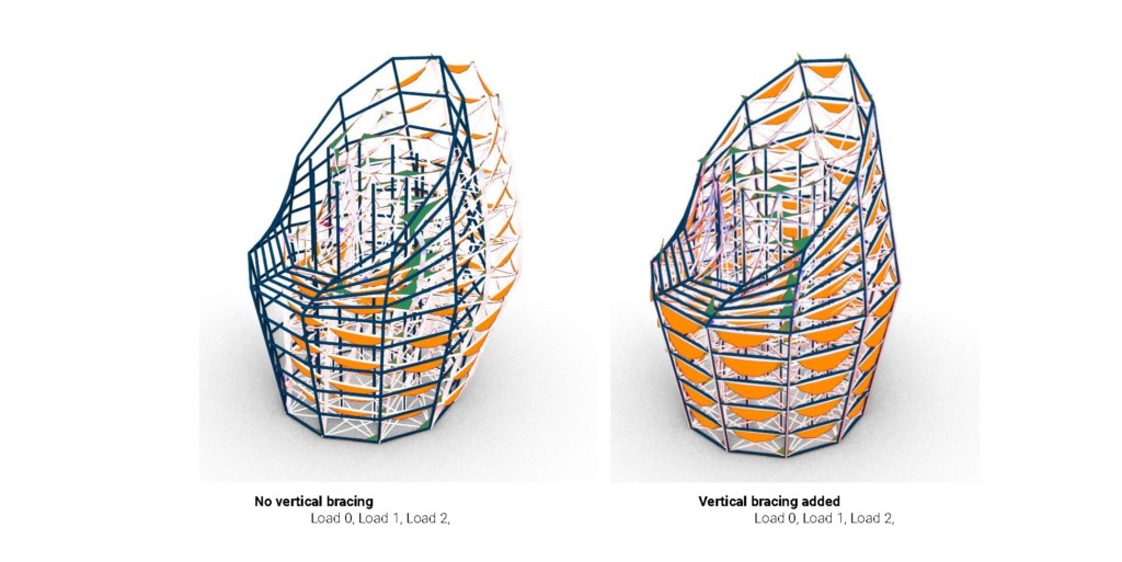
+ INNER CORE // Adding vertical supports
+ INNER CORE // Final optimized form
+ OUTER CORE // Parameter and structure setup
We decided to use the same system just change the core from being an internal core to an external one.
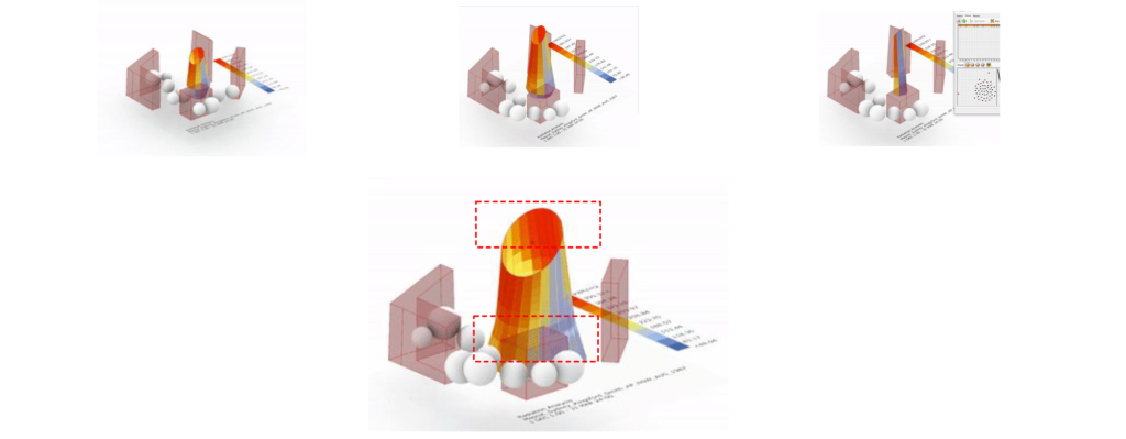
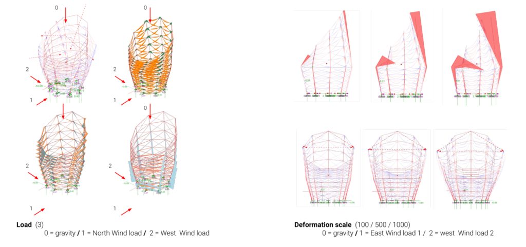
+ OUTER CORE // Global Displacement
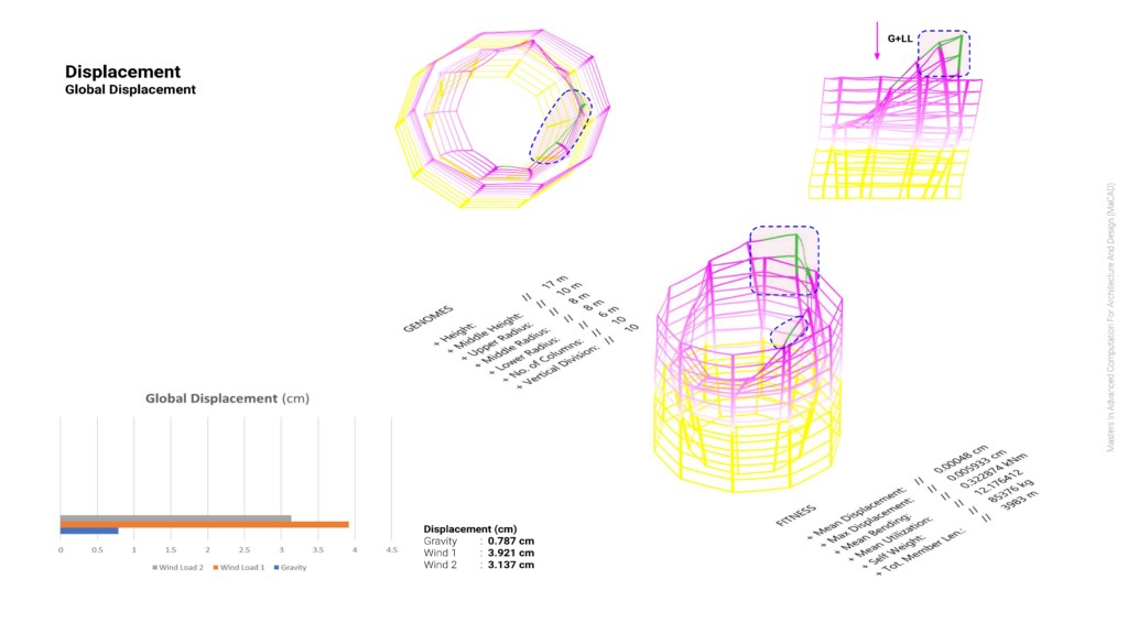
- The displacement is highest in the region where the tower extends to capture the air. The core is not connected to it and so it has no lateral support. The structure is displaced downwards due to gravity and self-weight.
- The highest part of the tower needs lateral support of some sort. Maybe we cloud tie it to the core using cables.
+ OUTER CORE // Gravity Load Displacement
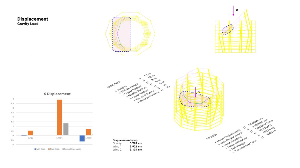
- Lateral displacement is almost nonexistent in most of the structure, the structure displaces facing downwards due to self-weight and gravity. The region with the largest displacement possibly is affected by its orientation, being directed inwards and held by cables might mean it’s pulling down using its self-weight.
- The displaced area may need to be pulled up from other corners laterally and opposite to each other. Fixing its orientation/changing its cross-section/ material.
+ OUTER CORE // First Wind Load Displacement
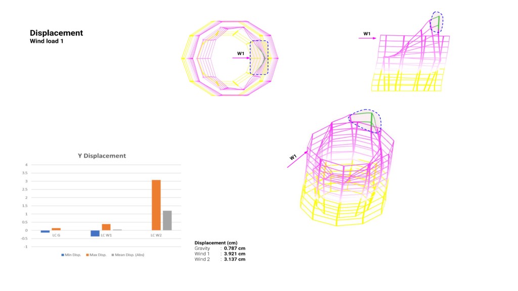
- The displacement is highest in the region where the tower extends to capture the air. The core is not connected to it and so it has no lateral support.
- The highest part of the tower needs lateral support of some sort. Maybe we could tie it to the core using cables.
+ OUTER CORE // Second Wind Load Displacement
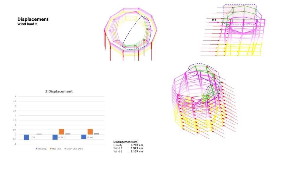
- The displacement is highest in the region where the tower extends without support from the core and hence it has no lateral support.
- The highest part of the tower needs lateral support of some sort. Maybe we could tie it to the core using cables from a distance.
+ OUTER CORE // Global Utilization
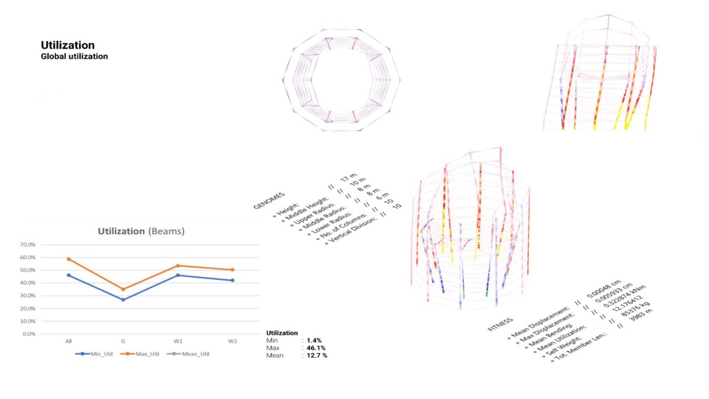
- The utilization is mainly in the columns and it seems that the columns are undergoing bending in each connection.
- Disconnecting the columns midway may reduce the moment. A balancing member may be used to reduce the moment and rotation.
+ OUTER CORE // Bending by Gravity load
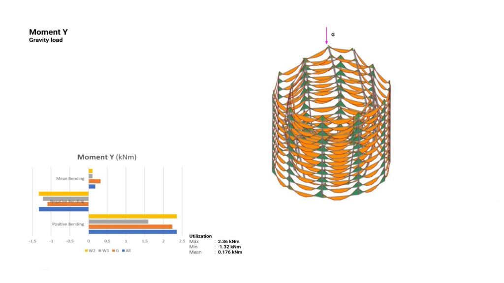
- The moment is traveling through the beams normally.
- We will consider releasing some elements and supporting with one row.
+ OUTER CORE // Global Axial force
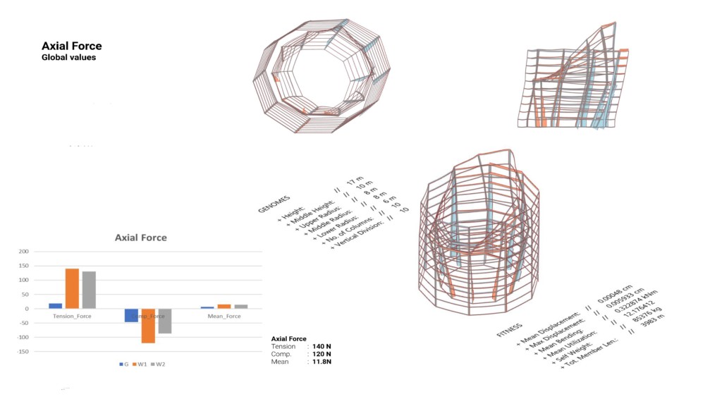
The force is traveling as expected in the columns with the columns on the receiving end of the wind load are in tension while the columns opposite to it are in compression which makes sense if we consider that the columns are inclined inwards and not straight and the need for tension and compression to balance each other for stability. Interestingly the outer columns have almost no forces in them, transferring the loads to the inclined central columns.
Restore and Reconnect is a project of IAAC, Institute for Advanced Architecture of Catalonia developed in the MaCAD 2022 by:
Students: Danna Priyatna, Alexander Lopez, and Basel Ghazaly.
Faculty: Manja van de Worp, Matthew Gabe