Project Overview
Re-Play is a rewilding project with the objective of cleaning a contaminated and ignored riverfront site at the outskirts of Madrid. With its rich history of play and natural space, this project intervenes the site with an eco-center and play area to reinvigorate the land and reconnect with people and nature. This intervention is done through the introduction of a lattice structure that integrates into the landscape and creates circulation and programming.
Site
Located along the Rio Manzanares, NW of the Madrid’s central core. The project is set where Playa de De Madrid used to stand. Once a large recreational club for the areas working class, Playa de Madrid included multiple tennis courts, swimming pools, cafes and a large man made beach, created by daming the river.
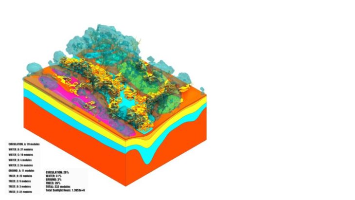
The basis of the project consists of a series of a district set of modules to create a play space field condition a long the site.
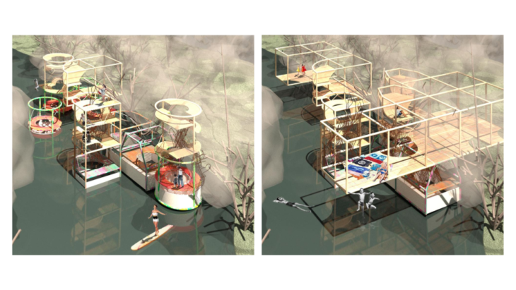
The modules measure 5x5x5 m and are designed to the different parameters and or features of site; circulation, water, ground and tree. “Super Furniture” is placed within modules to create spatial elements with ambiguous functions.
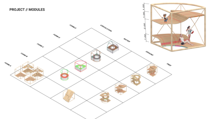
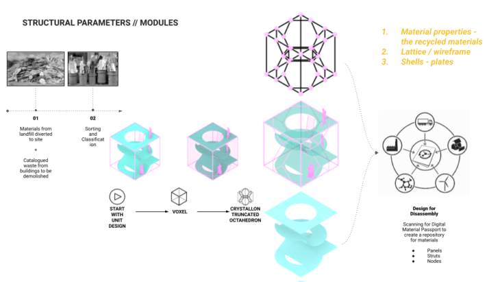
Modules – Structural Development
Given that the modules create the basis of the project, the first step in ensuring structural integrity was to optimize each module, using crystalon. This added cross bracing within each unit where moments of instability occur.
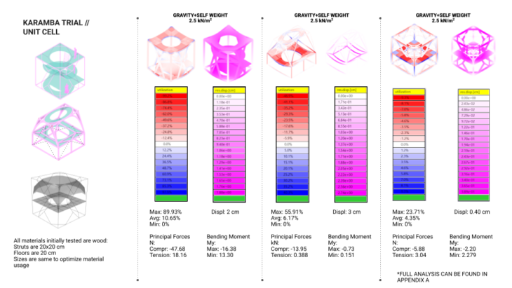
The unit cells where the first to be analyzed in Karamba. While a couple inputs where helpful in determining section dimensions and materiality we quickly learnt that once the modules are amalgamated into a larger structure they will take on completely different structural properties, it therefore became important to examine the structure in its entirety and understand the relationship between modules, and where modifications where required in order to optimize the structure in its entirety. This would best we achieved through a 2D global geometry analyses
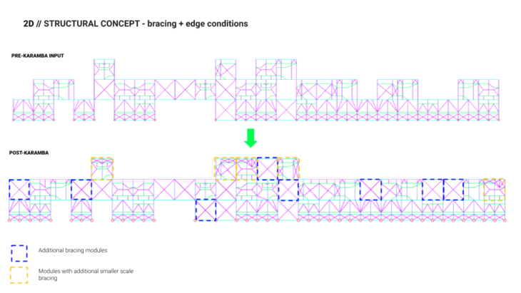
2D Global Geometry
The projects formal rules translated very well into the structural schemata.
The rules are as follows:
- Beams must be placed at 1,2, 3 and 4 m heights within the 5x5x5m modules is the main rule for the project’s structural, and formal scheme..
- Thicker wood sections (20cm x 20cm) outline the modules beams columns, and smaller wood sections (10cm x 10cm) are used for internal structural fill and bracing.
Force Flows: Vertical continuity is strong while horizontal connections are more sporadic due to the “superfurniture”, ie structural fill of the modules vary in which rule heights they adhere too – for example module A’s structural fill is only placed at elevation height 0 and 3, where as Module D has structural fill at all aforementioned rule heights. So when amalgamated the global geometry disrupts a strict grid and creates a honeycomb like condition, similar to house N/A shown earlier in the semester. Therefore horizontal force flows are not sent to one main structural core, rather they are spread throughout the structure. This approach alignes with the concepts, as the project is envisioned as growing over time, in small clusters, and is therefore freed from having to connect back to a structural core.

Bracing + Shear Walls: Once entered into Karamba it became evident that the large scale, global model needed additional bracing where there were gaps/openings in the structure. Additionally modules on the 2nd story of the structure, at the ends required additional bracing in order to withstand wind forces, and all 3rd story modules require additional bracing to counteract gravitational pull, live loads and wind forces.
The large bracing modules act as shear walls, where loads are transferred throughout the honeycomb structure.
2D Global Geometry Analysis
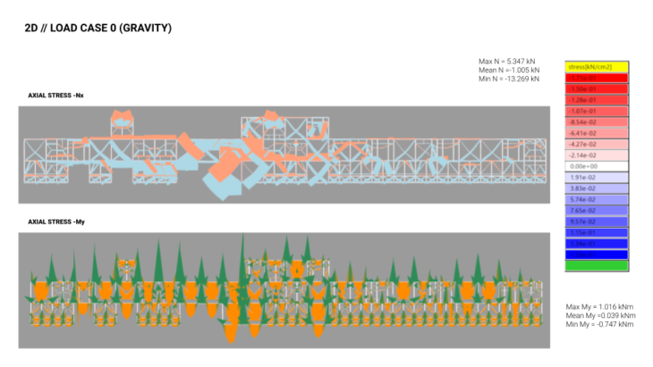
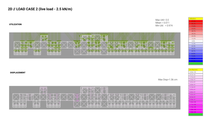
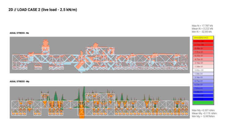
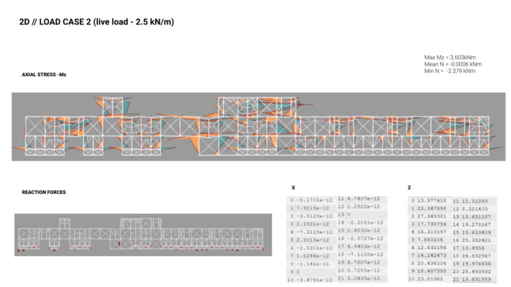
The graphics below are a summary of the karamba analysis of the global 2D geometry using three different load cases (gravity, wind, live load)
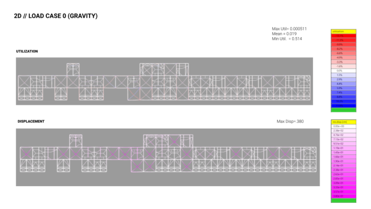
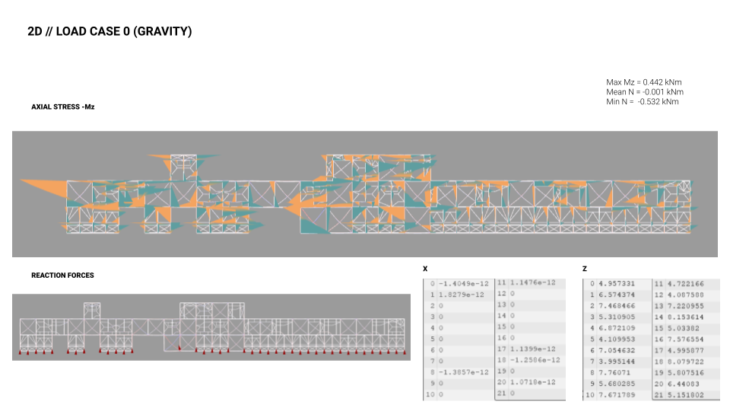
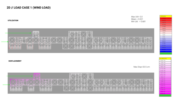
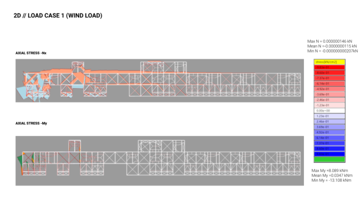
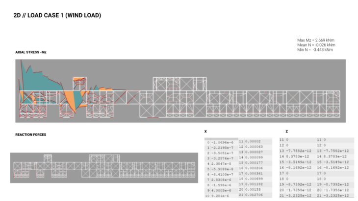
The following observations and conclusions where made:
Load case 0 : The Nx and My diagrams demonstrates the shear walls throughout the structure at work where loads transfer throughout the structure and the largest moment occurs at the large scale bracing. Although numbers are high, we hope 3D shell analysis will reduce moment in 3D analysis
Load case 1: Large levels of tension at the wind contact area and slowly dissipates. Conceptually this scheme is working, we anticipate it will transfer well in shell analysis
Load case 2: Very high utilization level and moment in live load, more bracing will be necessary, again something that will be addressed with shell analysis
While the global 2D analysis was very helpful in determining the relationship between modules, and the global structural concept, a 3D, shell analysis was necessary in order to understand how the floor plates/structural infill would contribute to stability and load transference of the sheer walls
3D Chunk
A “chunk” of the project was used for this analysis, as it would provide a sample of how the floor plates and bracing work together.
After a few previous trials of unit cell analyses and 3D chunk analyses, we landed upon the shear wall as a core feature. Using some of the units as shear walls cores especially in the empty spaces with no modules became the general direction. This iteration used cross bracing as a repeating element. Any gaps between asymmetric adjacencies were also populated with cross bracing to resist lateral loading. As the material grows and a complete analysis is populated on the entire aggregation, more cross bracing cores would be added leading to a distributed stability model.

3D Chunk analysis
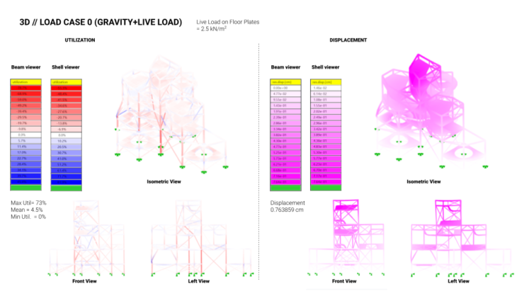
The graphics below are a summary of the karamba analysis of the 3D geometry using three different load cases (gravity, wind, live load)
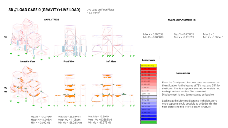

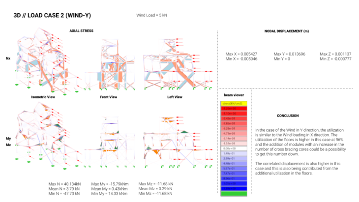
The following observations and conclusions where made:
load case 0: For Gravity, the utilization and displacement is working in ideal ranges and some more support could be added for the floor plates to counter the Moment.
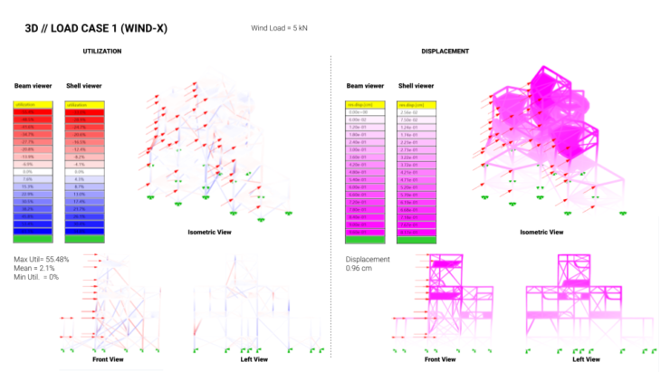
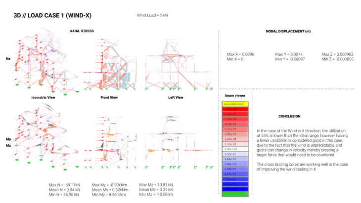
load case 1: For Wind in X, the utilization is good although lower than ideal but when considering wind gusts or increased loading in X, this would be to our advantage.
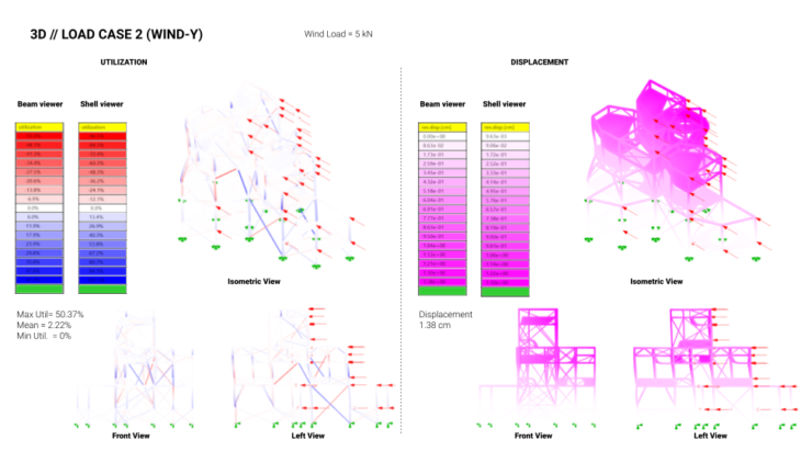
load case 2: For wind in Y, the beam utilization is good but the shell utilization is higher. With the addition of more modules when considering the growth of the aggregation of the structure, it could help in lowering this utilization due to the addition of more cross bracing cores.
CONCLUSION
The project’s structural concept was sound, and, in many ways was successful, as seen in the analysis highlighted above. However greater refinement was necessary in, particularly in the area of moment reduction. As one of the juror’s in the courses final critique pointed out – when high levels of moment are occurring designers should not increase material thickness, rather spans should be reduced. With this knowledge in hand returning to the individual module designs and reducing the material spans would, we theorize, reduce the moment occurrence in the overall structure.
RE-PLAY Structural Analysis is a project of IAAC, Institute for Advanced Architecture of Catalonia developed in the Master In Advanced Computation For Architecture & Design 2021/2022 by Students: Zoe Lewis, Salvador Calgua, Sumer Matharu and Jacinto Moros Montañés; Lead Faculty: Manja van de Worp; Faculty Assistant: Matt Gabe