PUBLIC CULTURE CENTER IN MADRID_ Algorithmic problem solving methodology for form finding and facade design
Project of IAAC, Institute for Advanced Architecture of Catalonia developed at Master in Advanced Computation for Architecture & Design in 2020/21 by:
KIM Kyunghwan and Jaime Cordero Cerrillo
lead faculty: Rodrigo Aguirre faculty assistant: Oana Taut
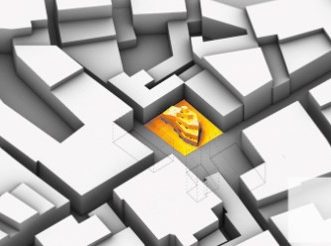
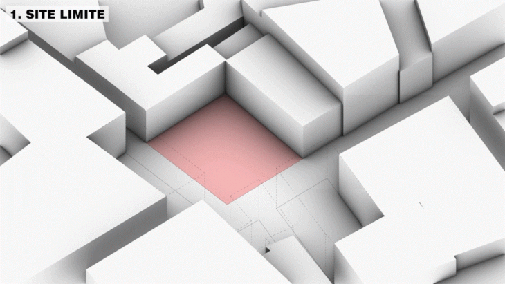
SITE
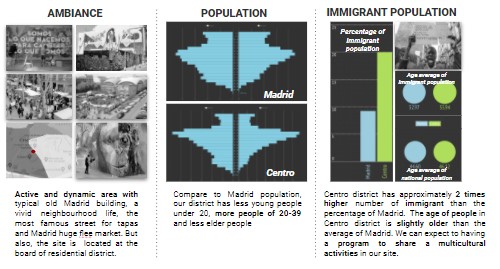
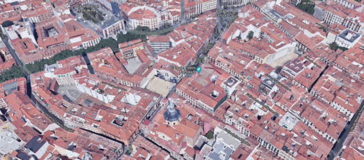 Nested between La Latina & Lavapies urban districts within Madrid, these neighborhoods capture a historic element within its inhabitants with a multicultural immigrant population, thus attracting many visitors & tourists. The area is vibrant with it’s nightlife, large plazas and pedestrian friendly streetscape. The building facades are consistent with narrow wrought iron balconies and coloured in mortar & pastel with 4-5 levels, divided into residential flats and commercial / retail on the main floor. The area is unique with its steep hills, creating an effect with it’s spatial orientation compared to the rest of Madrid.
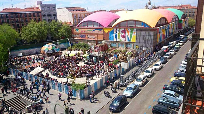
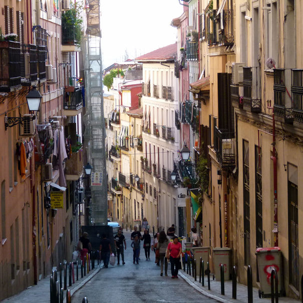
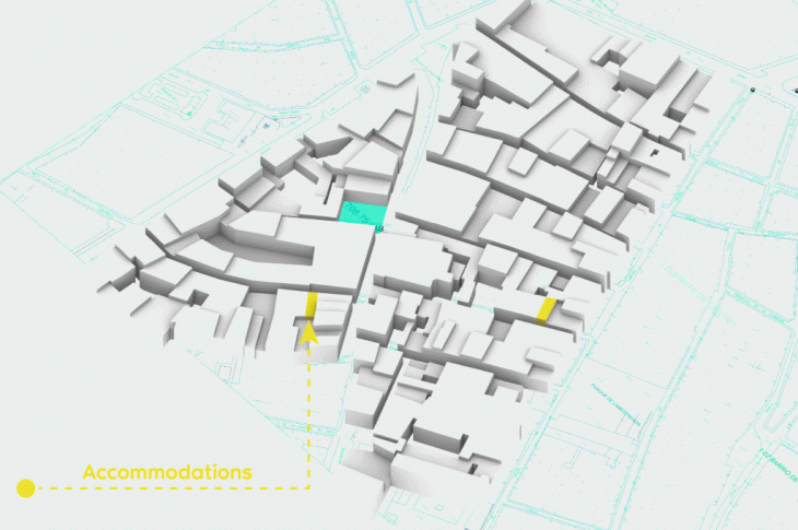
Our site clusters within a majestic corridor with a bohemian subculture that is a reminder of it’s multicultural demographics. The area is activated with bars, cafe’s and a bohemian vibe by activating abandoned buildings or terraces with artistic & musical gatherings, giving life and purpose to the district. The empowerment of pedestrian activity within these spaces has lowered car-use and promoted economic vitality within its commercial corridors. The site is in a very dynamic and active area. The street of our site works as a hinge between these two neighborhoods, something that we considered when designing, taking into account the circulation of this area. Although there is a lot of activity over the area, and it is a very multicultural district, there is an important lack of public space.
CONTEXT ANALYSIS
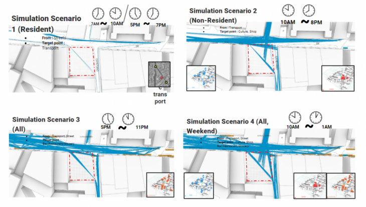
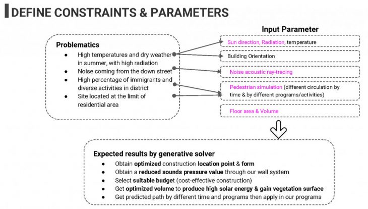
To study how circulation around our site takes place we analyzed using Pedsim how people would move around it and through our site because of the activity that it’s surrounding it. We considered four different scenarios, taking into account the different activities that people could develop.
 (a)
(a)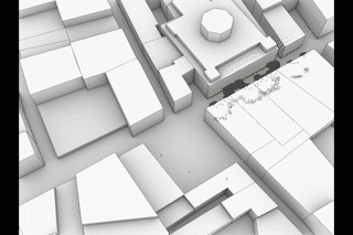 (b)
(b)
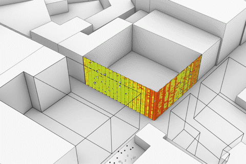
*(a): Here, we test with a 2 surfaces that may represent a facade on our site. We can see the different sound level that cross the surface. Sound pressure level going to decrease and the edge at the junction face to most of the sound energy.
(b): Energy of the particle that represent sounds pressure level is getting weak by spreading out to the street. However, a number of amount of particles comes and floating for a while in our site.
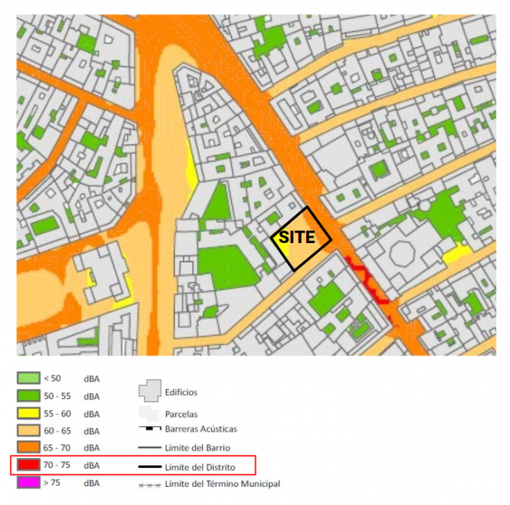
From the municipal noise map, we found out that there is a noise over 70 dBA near our site where are a historical cathedral and bars. Therefore, we simulate the site with Pachdem and Snail tools to observe the movement of sounds particles.
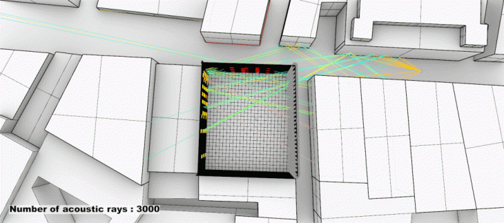
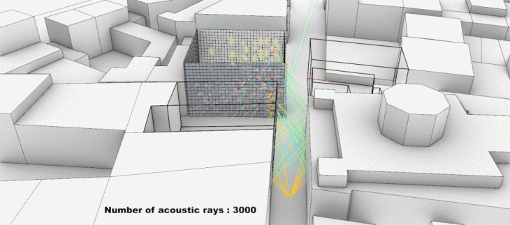
*(c)Acoustic Ray tracing Analysis for the noise from the street.
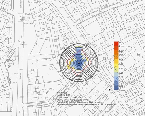 (d)Wind rose and Dry temperature
Wind doesn’t have any important effect. It comes mainly from the north but after running CFD Simulations we saw that because of the density of the city it follows the street directions.
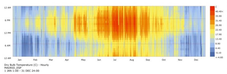
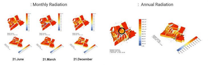 (e) Annual temperature and Radiation analysis
Temperatures are really high in summer, being the hottest month of July, when solar radiation is also high. During winter temperatures are around 0 to 5°C.
CONCEPT & OBJECTIVES


We propose a public cultural center that allows inhabitants to share their culture and lifestyle through our building. Our culture center will welcome people by offering flexible community programs. With the computational analysis of the site’s environment, we expect to have an adaptive design regarding heat energy and noise. Through material and a configuration of modular wall systems, this architecture will have a function to reduce the noise of the district. But also, this modular block system allows people to cultivate vegetation in order to make together an eco-city.
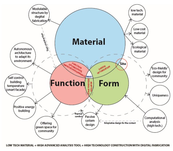
To offer more sustainable architecture, we will use low tech materials. But also, for the flexibility and long life span of the building, the modular wall could be fixed at the main frame structure and core. This aspect of the building may change the view of the district whenever the other function is demanded.
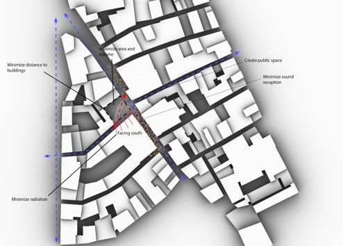
OPTIMIZATION I
The first optimization rules were
- Maximize floor area
- Minimize distance to existing buildings
- Maximize building volume
- Minimize radiation
OPTIMIZATION II
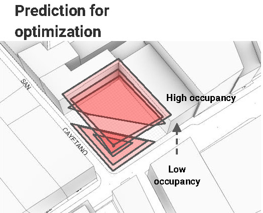
(f)Parameters for optimization(left) and prediction for form-finding optimization
The second optimization rules were
- 2 volumes of mass
- Maximum surface on top
- Circulation cross the site
- Maximize floor area
- Minimize distance to existing buildings
- Maximize building volume
- Minimize radiation
This optimization processes with the rules above gave a results that maximized floor area and volume but also with minimizing radiation for the facades. These methods weren’t very controllable so we went for the next optimization.
OPTIMIZATION III
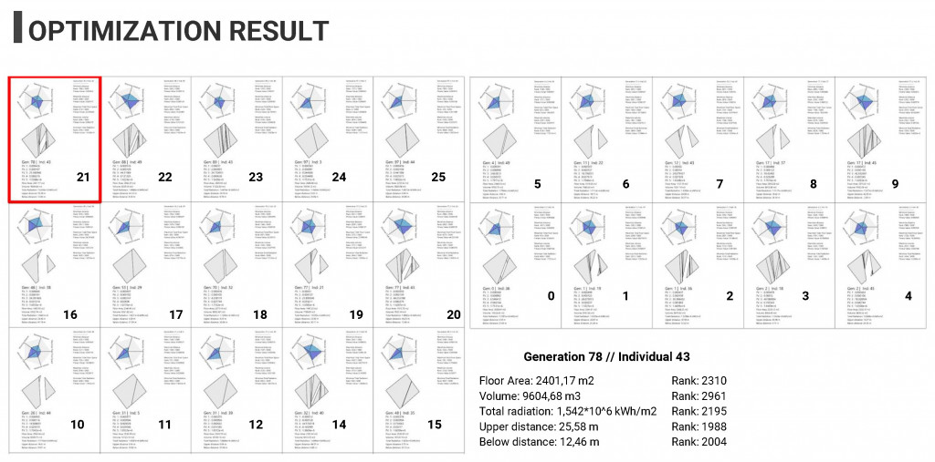
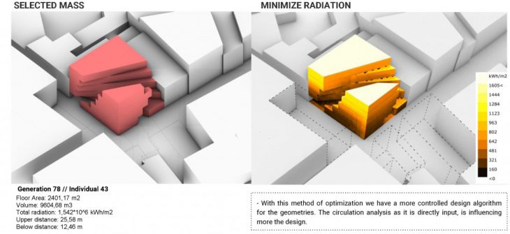
The thirds optimization rules were
- 2 volumes of mass
- Circulation cross the site
- Maximize floor area
- Minimize distance on the upper floors
- Maximize distance on the lower floors
- Maximize building volume
- Minimize radiation
After doing all these analysis, we parameterized it to be able to input it into our computational design process. We ran different optimization strategies until we found the one which suits more. Taking into account the circulation analysis extracted from Pedsim, we extracted the main circulation direction, which we copied up to all the 5 floors that our building would have, and then rotated and offset it to create a space between the two buildings. Using these rules, we set fitness values for optimization, to minimize radiation, to maximize building area and volume, and to maximize the lower public space area.
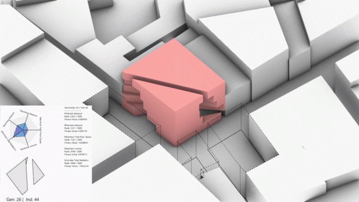 * Example of the form-finding optimization
STRUCTURAL ANALYSIS
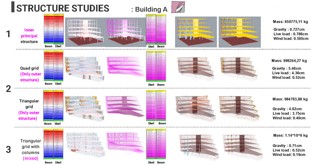
After the form-finding process, we did some structural studies. We started by doing an inner principal structure, with columns and a core inside, but we wanted to have a free and flexible interior space so we tried to have only an outer structure. We studied how it would be with just an outer quad structural grid, but it had a lot of utilization and a high mass, we studied then a triangular grid which worked better but still had high utilization, so we had to combine them by including a few columns on the inside.
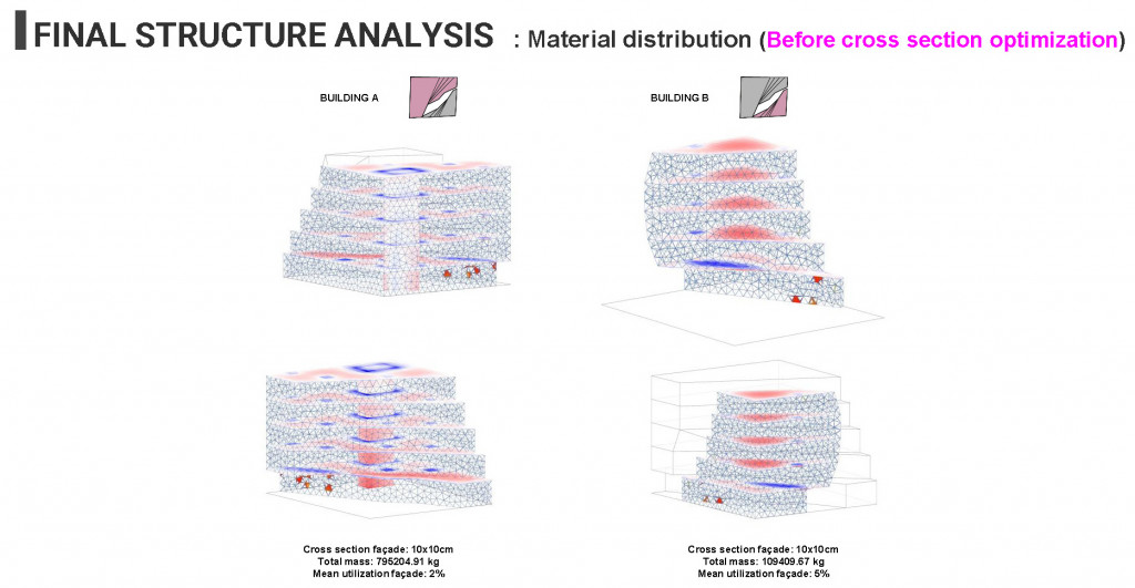
After these studies we saw that we had a very disproportional material distribution, with some elements which weren’t utilized at all and we had a really low mean utilization. So we decided to optimize the cross section of the triangular facade grid depending on the utilization and the stress.
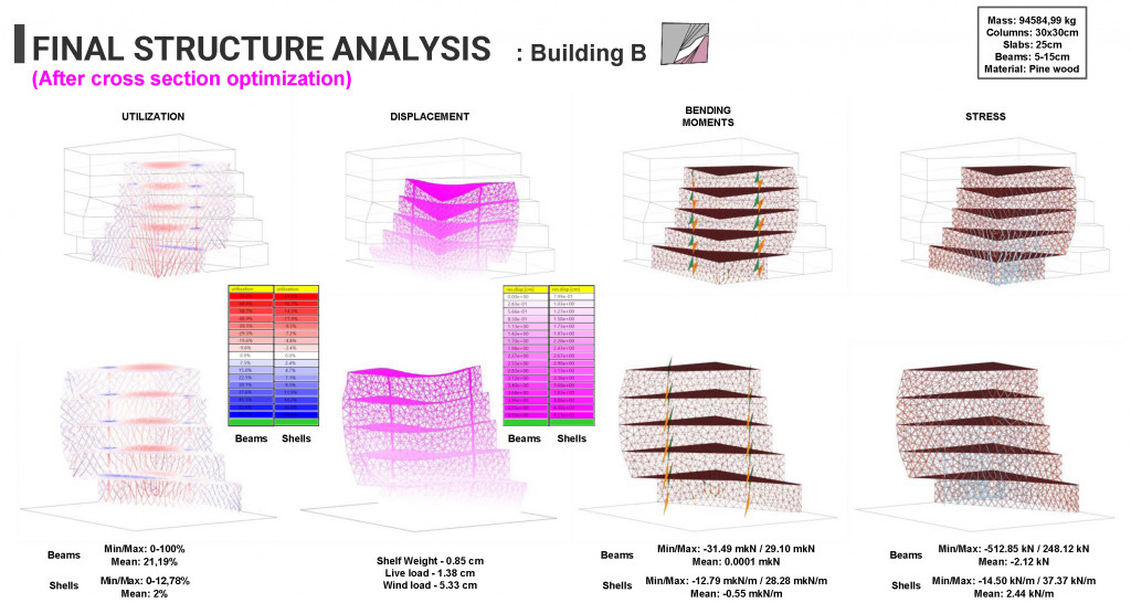
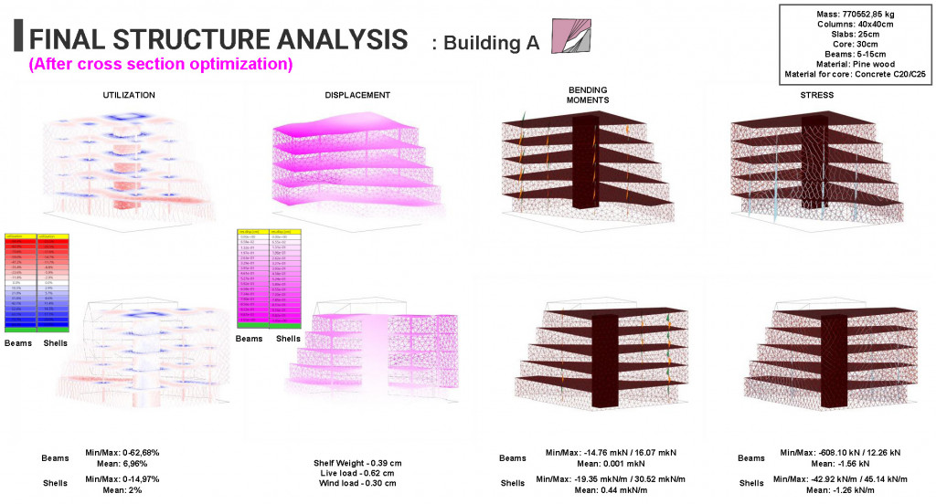
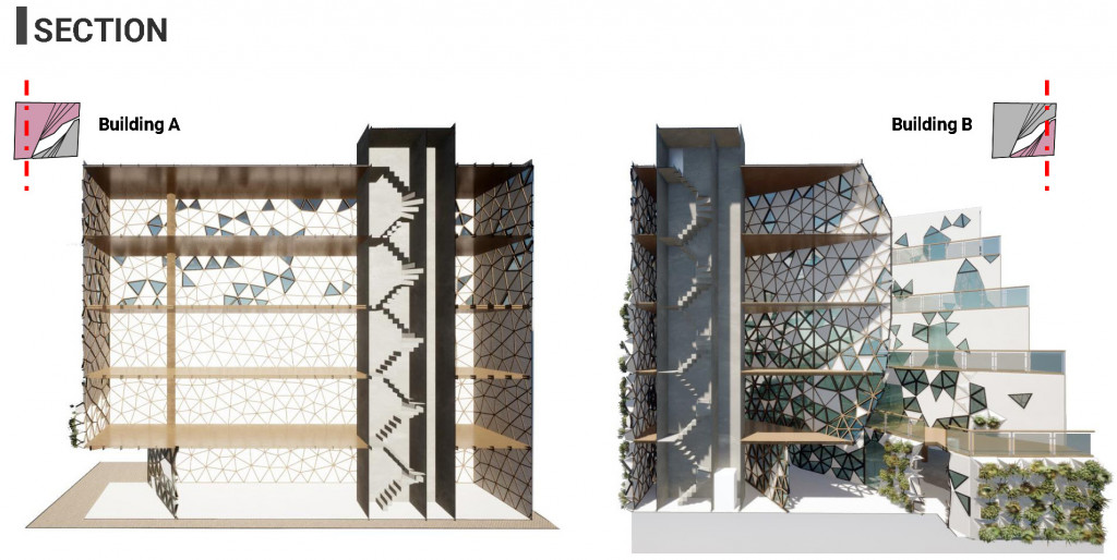
In order to combine our facade design and mesh opening analysis result, we used our façade triangular mesh. For the outer grid structure, we were using a 10x10cm pine wood cross section. But we saw that we had a very disproportional material distribution, with some elements which weren’t utilized at all and we had a really low mean utilization on the façade. That’s why we decided to optimize the cross section of the façade grid depending on the utilization and the stress. In the result, 3.2% of the mass for the building A and 15.7% for the building B.
To test different stability systems for the cantilevers, as we mentioned before we included a core in building A with just a few columns and just two lines of columns plus of course the grid in building B, which has bigger mean values of utilization, displacement and bending moments.
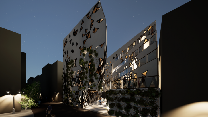
ARCHITECTURAL DEVELOPMENT
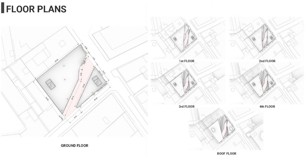
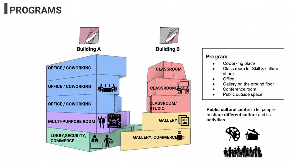
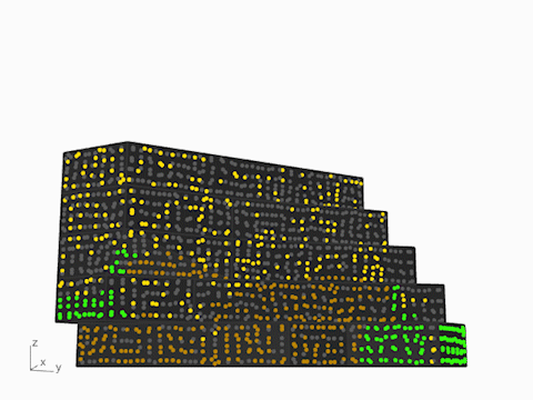
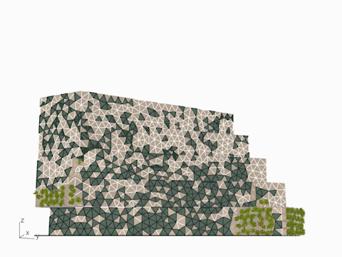
This public cultural center is combined by 2 buildings. The one in the corner of the site has a Lobby, multi-purpose room and offices. Another building which is bordered on streets has galleries and classrooms for skill & culture sharing of inhabitants. The programs are related with the issue of privacy for users, for examples, we gave more % of openings for public spaces which are ground and 1st floor.
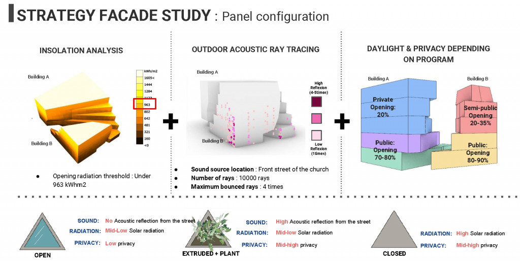
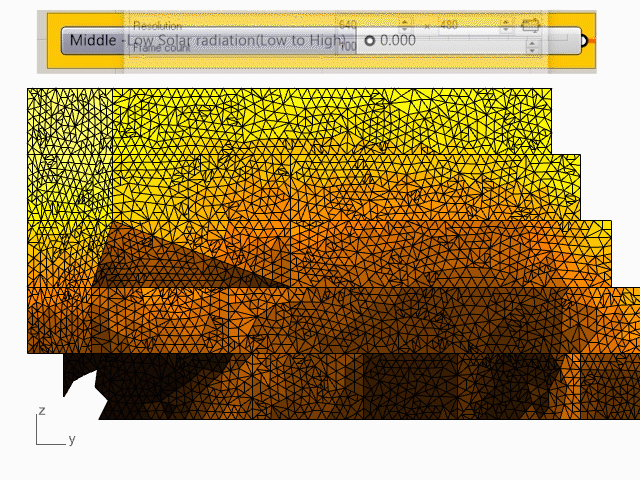
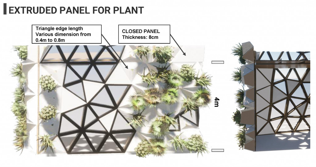
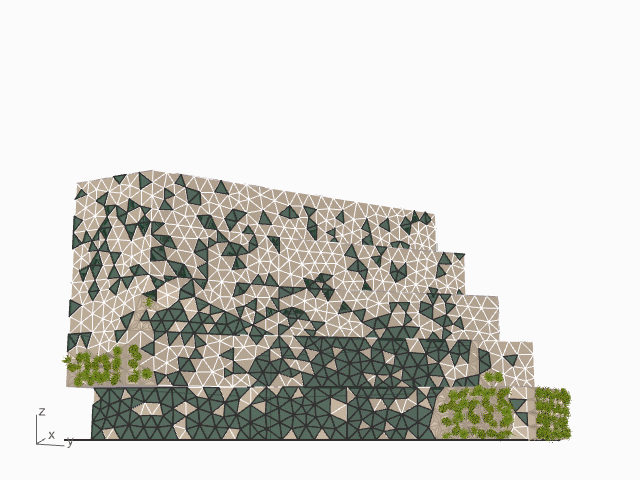
For the public cultural center, our principal question was how should we combine all of our analysis of noise, solar radiation and programs for the facade design. The openings on Facade and privacy issues are studied based on the solar radiation meshes. These triangles meshes of solar radiation were also an input for an acoustic ray-tracing. The triangular meshes used as panels of the facade. For examples, where it has a high radiation, and mid-high privacy, we gave closed panels. The extruded volumetric panel is given for the area which has a high acoustic reflection from the street. Windows were made for the zone which aren’t affected by acoustic reflection , low privacy program and solar radiation.
View of panels and window.
This method allowed us to test many variations of facade along the value of privacy and radiation percentage values. In conclusion, we could get a 2 proposition for a future client. The client can compare the number of panels and windows through our comparison images and graphs.
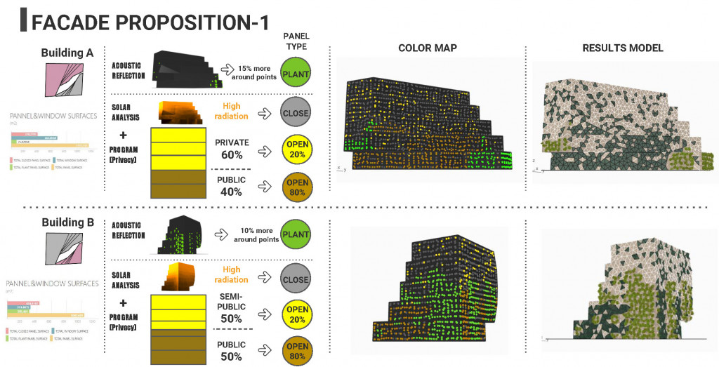
For Facade design, We divide the 5 floors by % of Public and private then divide again this value for openings. So We gave same 20% opening for offices which quite private on Building A, and Classes rooms which is semi public space. Building B is more close to public so that we gave 50%.
Proposition 1
 Building A
  Building B
Building ABuilding B
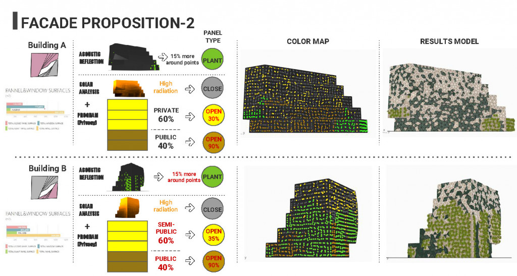
Here, we gave 60% and upper three floor for both building then increase openings. In the result, compare to the 1st proposition, 67.50m2 for the Building A and 140.50m2 for the Building B are increased.
Proposition 2
 Building A
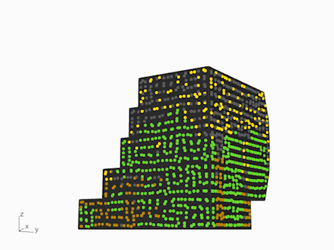 Building B
 Building A
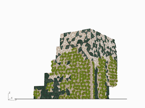 Building B
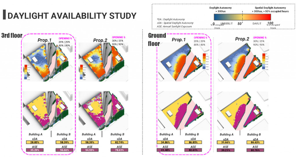
The next question for us was how can we decide which design is better for a future client? We use daylight availability study as the decision maker by predicting the interior thermal comfort for users. The red colour represents the zone of over 50% occupied hours by daylight autonomy. At the test of Annual Sunlight exposure, the proposition 1 has less purple area zone than the second proposition. It means that there is less potential area for glare or overheating by daylight. Therefore, we chose Proposition 1 as a better facade design.
Final facade design elevation.
VIDEO: Construction:
https://drive.google.com/drive/u/0/folders/1CTxzCLfAlLL6nHnSCqOoi-tpSE5r9xRg
VIDEO: Perspective view animation :
https://drive.google.com/file/d/1Oc4GEOeFv4ftKYYbMe5rP6RaAvVZ2MWN/view?usp=sharing
*Related projects:
Structure
Environment