Pothole Hunter was developed for practice in designing, building and programming with sensor feedback. Developed in a ‘Hardware’ module of the MRAC course, the bot requires also python and other software programming to get the hardware to work as a roving bot capable of responding to specific objects detected by its sensors.
The initial concept was to build a small mobile robot to simulate detecting and filling potholes, which would require the ability to:
? recognize and detect potholes
? navigate to the closest pothole
? manouevre correctly to position an end effector directly over the pothole (althought this is done without the pothole remaining in the field of vision)
? fill the pothole
? continue to next pothole
In practice, the goals were scaled back while maintaining the core goal of learning to build and program a complete bot with sensor feedback. In practice the desired ability of recognizing and detecting potholes was simplified to recognizing and detecting ‘blobs’ within a colour range – in fact oranges as can be seen in the videos below! This simplification was mainly due to time constraints, brought about mainly by an unfortunate situation in which the timing of the develpment of the project came immediately after the release of the updated Raspberry Pi IV microcomputers but before any new software for the new ‘camera stack’ was generally available. This resulted in quite a lot of time being spent unsuccessfully trying to use the Raspberry Pi IV and the new official Raspberry Pi camera module together, which had to be abandoned due to the lack of software available at the time, and having to opt for an alternative object-recognition hardware/software solution, in a reduced timeframe. This is why the blog post contains some images with the Raspberry Pi camera module mounted in the bot, but the videos in fact use a mobile phone attached to the bot in order to use its camera instead.
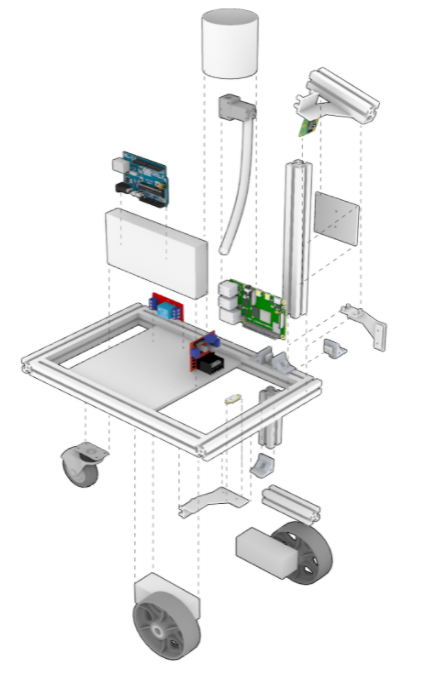
Hardware Overview
The bot uses a simple rectangular aluminium frame (universally available 20mm x 20mm extrusion) below which are mounted two motorized wheels (DC motors with encoders, and motor drivers) and a castor wheel and above which is mounted the remaining hardware: an Arduino Uno R3 microprocessor (blue in image below) controls the motion system, a Raspberry Pi 4 microprocessor was intended to control the vision system, a Raspberry Pi V2 camera (both green in image below) but in the end a mobile phone was used as a camera (and off-board image processing was used instead of the Rapsberry Pi 4). A 12V solenoid controlled the release of a liquid from a recipient to a tube which deposited it where the ‘pothole’ was. A distance sensor was positioned to detect when the liquid filled the ‘pothole’ to the required level. Screw couplings, 5V regulators, 3S Lipo batteries and some 3D printed parts completed the set up.
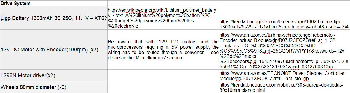
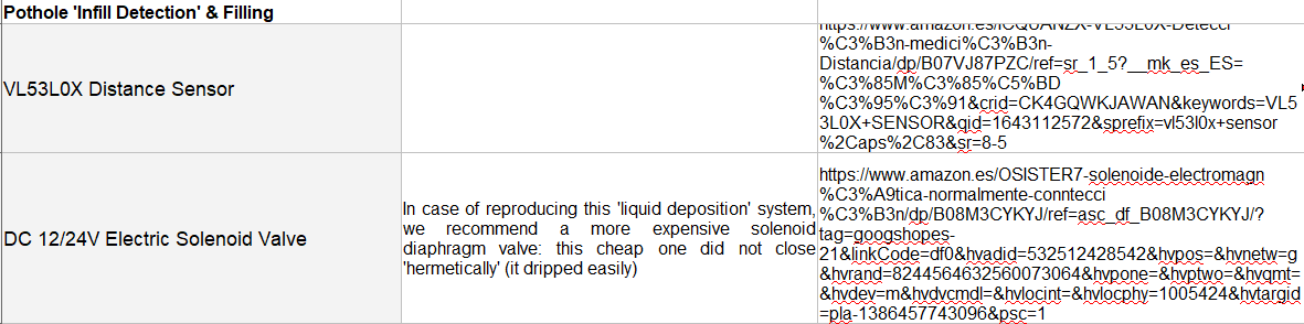
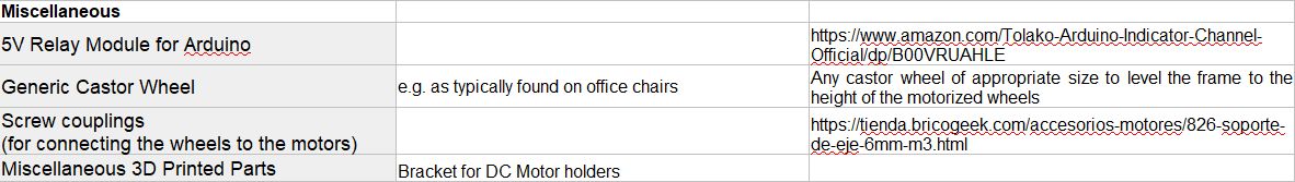
Hardware Bill Of Materials
If anyone could be interested in reproducing this bot either completely or partially, this table lists the hardware elements and a link to manufacturers information or suppliers.

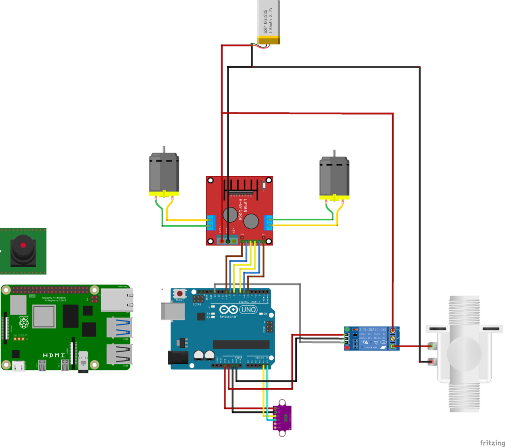
Core Electronic Component Connections
The diagram below shows the core electronic connections (if it is downloaded it is high enough resolution to zoom in and identify all connections in detail), but the Raspberry Pi and its camera are not included because finally we did not use them.
However, if we had managed to use the Raspberry Pi 4 with the Camera Module 2, the Raspberry Pi would have received power from the H-Bridge 5V outputs (bottom right hand in image – the same as those from the H-Bridge to the Arduino Uno), the camera is always connected directly to the Raspberry Pi 4 with a cable attached to the camera at purchase (connection details here:
https://projects.raspberrypi.org/en/projects/getting-started-with-picamera)
and the connection between the Raspberry Pi and the Arduino Uno would have been by USB.
Steering
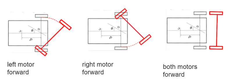
A key design element of the bot is the simplicity of the hardware layout for steering which allows relative simplicity in programming the bot’s motion.
The bot has three wheels. One, the rear wheel, is a non-motorized castor wheel – it can rotate about a vertical axis to be able to point and move in any direction, but simply following the lead set by the other two wheels, which are identical and motorized. In this arrangement, if the left hand wheel is driven forward while the right hand wheel remains stationary, the bot rotates to the right. And conversely, if the right hand wheel is driven forward while the left hand wheel remains stationary, the bot rotates to the left. Of course if both powered wheels are driven together at the same speed, the bot moves straight forward. These three options are shown schematically below.
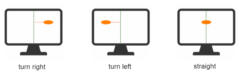
Simultaneously, our requirements in terms of navigating directly towards a detected object in the field of vision are very similar: assuming the vision system is looking straight forward in front of the bot, if an object is detected in the right hand part of the image, then the bot needs to be rotated to the right to be pointing straight at it. Conversely, if an object is detected in the left hand part of the image, then the bot needs to be rotated to the left to be pointing straight at it. Of course when an object is detected at the centre of the image the bot is already pointing straight at it and so needs to be driven stright forward to reach it. These three options are shown schematically below.
Pseudocode
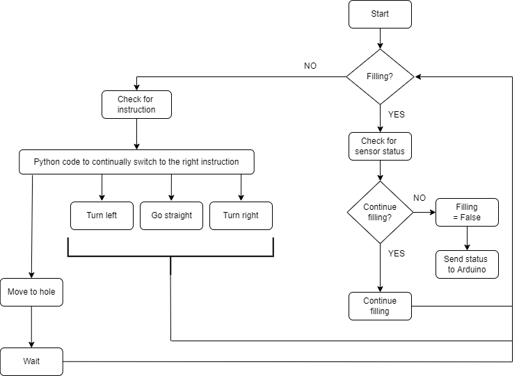
The logic of these simple movements is at the core of the ‘pseudocode’ which lets us move from what the vision system detects (an object in the left, centre, or right of a series of frames) to giving appropriate instructions to the wheels to achieve the desired goal – steering the bot until the detected object is at the bottom of the centre of the field of vision. When this is achieved, which is called ‘Oriented’ in the pseudocode image below, a fourth movement option (additional to Turn left, Go straight and Turn right) is programmed which is called ‘Move to hole’.
‘Move to hole’ is a movement straight forward the required distance to position the liquid-dispensing hardware of the bot, consisting of a small recipient a solenoid and a tube, directly over the point where the detected object left the field of vision.
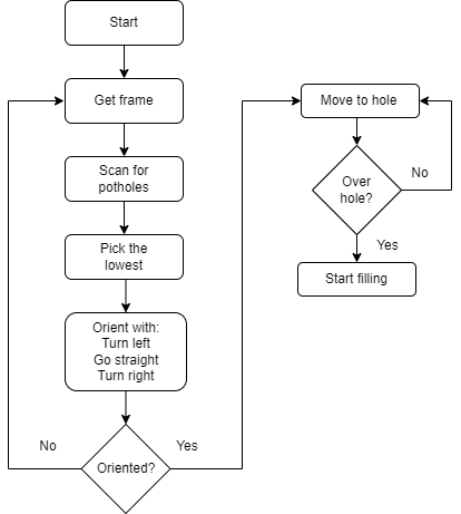
In the pseudocode below the entire process is shown. Unlike the pseudocode above which focuses on linking the vision system to the steering, the pseudocode below includes the process of filling the pothole. Our bot did have a functioning ‘pothole filling system’ – the solenoid was functional and programmed to begin to release liquid after the bot was positioned over the ‘pothole’ and to stop releasing liquid when a sensor detected a fill-level had been reached – but its use does not appear in any videos since our detection was restricted to orange blobs and not potholes.
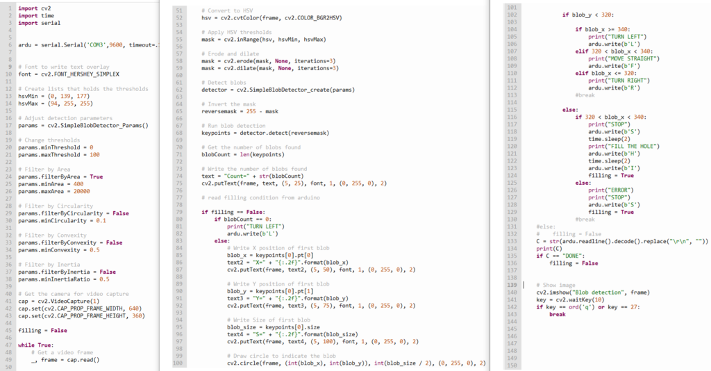
Actual Code
There is python code – pothole hunter.py – written to be run on the Raspberry Pi but finally run on a laptop because of the camera stack problems with the new Raspberry Pi 4. Here it is:
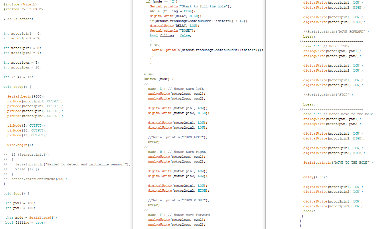
And there is the code on the Arduino Uno. Here it is:
(Lights,) Camera, ACTION
Here are a couple of videos of the bot doing what it’s programmed to do.
https://vimeo.com/manage/videos/695878261
https://vimeo.com/user156563278
Pothole Hunter is a project of IAAC, Institute for Advanced Architecture of Catalonia, developed at the Master of Robotics and Advanced Construction in 2021-2022 by:
Students: Huanyu Li, Libish Murugesan, Christopher Booth and Tomás Quijano
Faculty: Oscar Gonzalez, and Assistant Faculty: Daniil Koshelyuk