“A robot tool that can sculpt foam like an artist”
-Julia Neira | Designboom
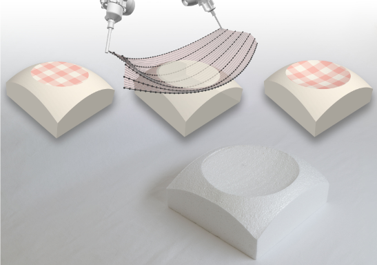
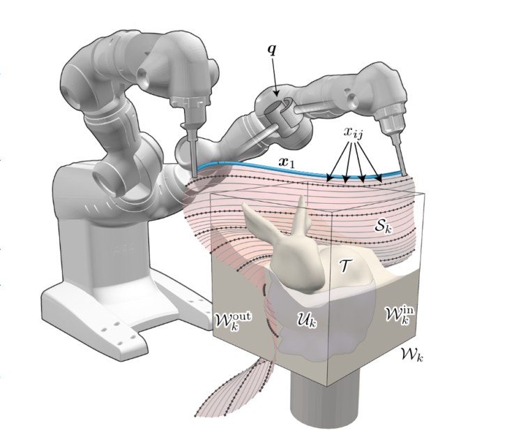
Commenting on the project developed at the ETH in Zurich that explored using a stretched hot wire cutter to sculpt foam. The Hot-Wire cutting applications for double-curved geometries was developed using two robotic arms in conjunction with each other to sculpt freeform shapes using a flexible hot wire cutter.
Source: RoboCut: Hot-wire Cutting with Robot-controlled Flexible Rods | ETH Zurich
Source: RoboCut: Hot-wire Cutting with Robot-controlled Flexible Rods | ETH Zurich
Concept Development
single curve through linear motion (simple ruled surface)
easily achieved using straight wire tool attached to robotic arm.
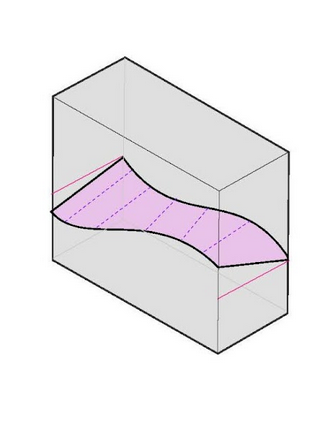
ruled surface
achieved using straight wire tool attached to robotic arm and introducing rotation along the tool path
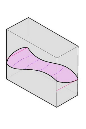
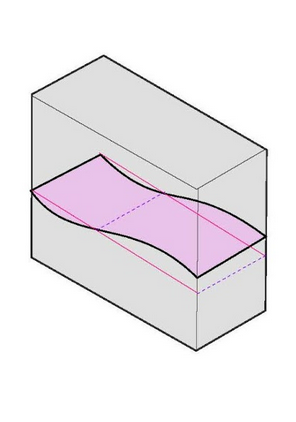
double curvature
requires curve transitions along the path. Rotation can also be introduced for additional complexity.
End-Effector Design
End-Effector Prototype 1.0_Design
End-Effector Prototype 1.1_Design
Curve generation
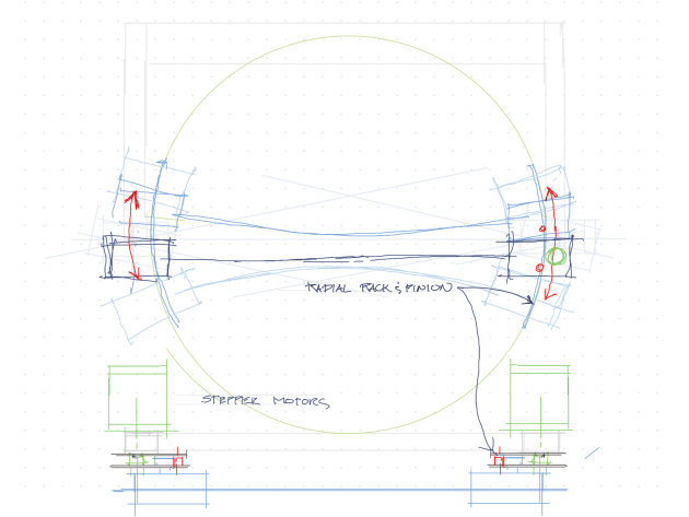
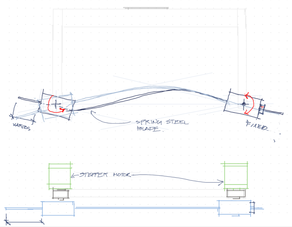
The mechanism for producing the curved blade is based on the on developing opposing tangents that in combination can produce arc splines and s-splines. The curve development would be determined by the tensile properties of the blade shape and material and the blades would have to be calibrated to be able to correlate a specified geometry with the output.
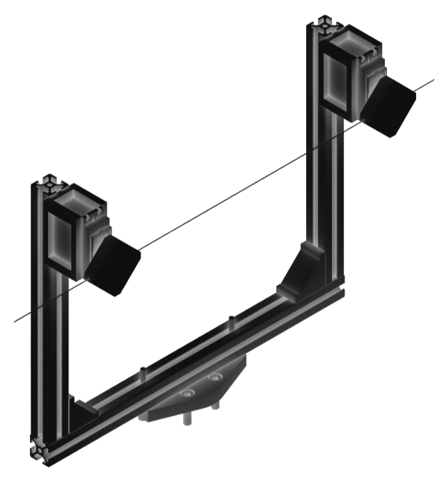
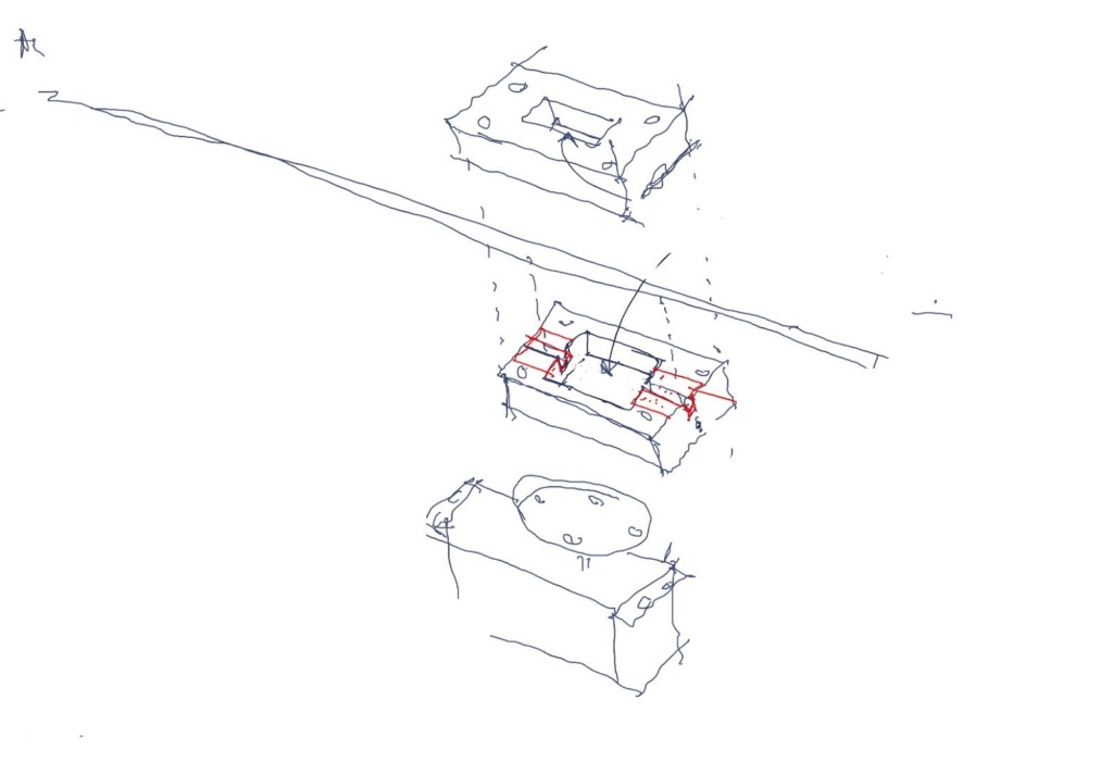
End-Effector Schematics
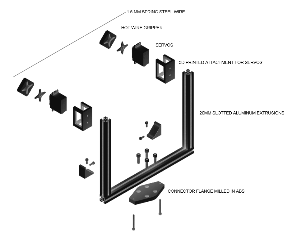
Exploded View of End-Effector 1.1.0
- Frame assembled using standard 20mm slotted aluminum extrusions and connection hardware.
- Servo mounts and hot-wire holders 3D printed in ABS
- Connector to robot milled in ABS
Prototype 1.1.0
Further refinement would include
- redesigning the wire holder so the tangent arcs have their ends at the axes of rotation of the servos
- gearing the servos to provide additional resolution to the curve.
Circuit layout
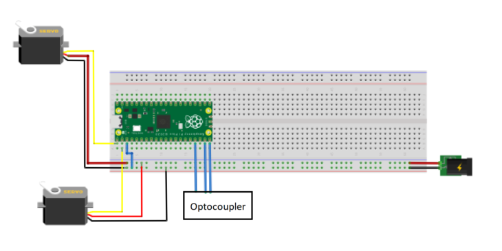
Angle Control
The ROS needs to send a signal in the form of an IO to the Pico as a series of on-off’s (true false) that can be interpreted as an angle. Since the angle is controlled based on the pulse width of the output signal, the IO could be constructed to input the binary equivalent of the pulse width. To simplify our prototype, we decided to limit the angle to (8) possible angles using (3) IO commands for each servo (23)
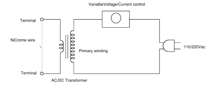
Hot-Wire Schematics
Hot-Wire Schematics
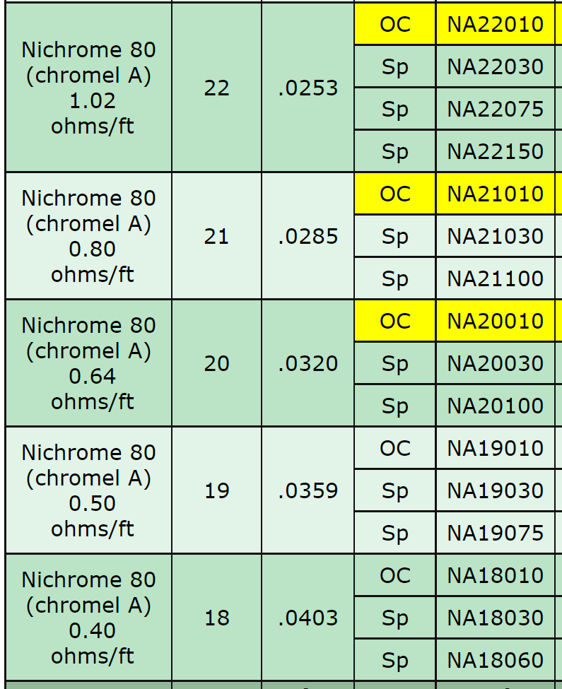
Resistance Table for Nichrome Wire
Implementation of Joules Law
The basic concept of a hot wire cutter is to produce heat through electrical friction, or resistance. The most common material for producing resistance is Nichrome wire of various grades. Line voltage is converted to a lower direct current to produce a higher current at a lower voltage which prevents the circuit from short circuiting. The resistivity of wire is difficult to calculate accurately and primarily derived from empirical data.
Cutting System
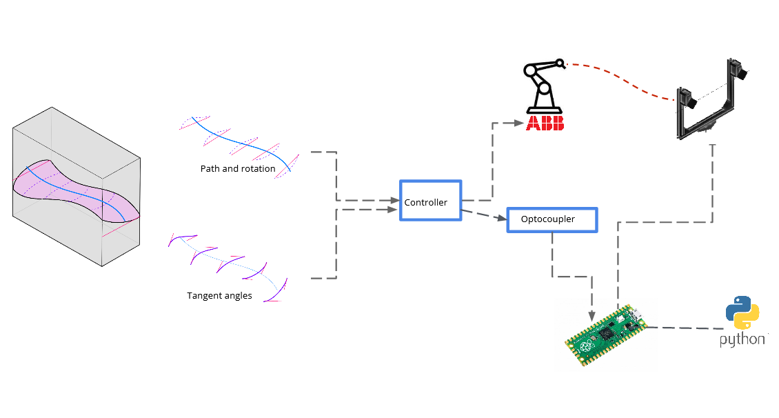
Interpreting geometry and communicating with robot
Geometry is broken down into instruction for the tool path/rotation and angle commands for each target plane and sent to the controller as a set of instructions. The controller passes the angle instruction to Pico through the optocoupler and the Pico communicates directly with the servo motors.
Simulation & Prototyping
Defining tool path and build volume for prototype
For the purpose of getting to ‘proof of concept’, the tool path would be simplified to a straight line path with a controlled distance to move having to account variables such as rotational and angular speed which would be needed to coordinate with the ability of the wire to “burn” off material and avoid inducing a force onto the blade.
The build volume would simply be determined by the range of the robot and the blade span.
Hot wire
Initial experimentation used hot wire. Early prototype failed because either the wire had the right resistance but not enough strength to hold the curve, or they could hold a curve, but had insufficient resistance to generate the required 600-800° C to burn off foam.
Clamp 2.0
Heat required to cut foam combined with the heavier gauge of the wire is more than sufficient to melt PVC or PLA plastic
In addition to adding ceramic insulating tape or to the wire, it would be possible to use a fluid or spray applied ceramic coating such as CERAKOTE. Since the wire is being bent primarily from the front and rear edges, the center portion of the holder could be cut out further reducing the the thermal transfer
Carbon Steel and Stainless Steel Spring Wire
Materials used for experimenting were based on available materials within the time frame of the project. Further experimentation with different gauges of stainless steel spring wire would be beneficial. Stainless steel required about half the current of the carbon steel wire to cut the foam for the same thickness of wire while for the same thickness,
Longer wire would also produce better results. It may seem counter-intuitive, but the longer wire has more resistance and while it will take longer to reach thermal equilibrium, it would produce more uniform heat. The back span on the spline would allow us to give the wire greater flextural strength by allowing the stress to be spread more evenly instead of being concentrated on the leading edge of the servo connection
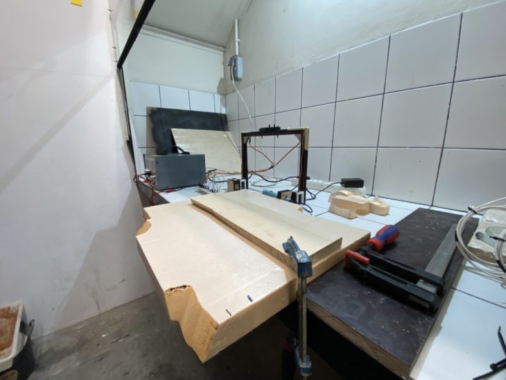
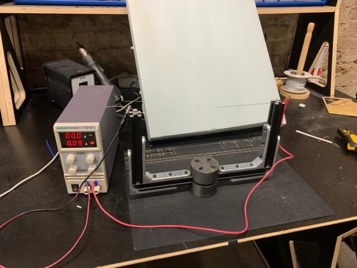
Beta_Test Cutting setup
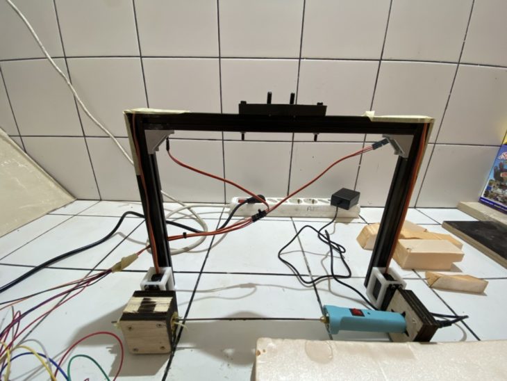
End-Effector with Hot-Wire Knife
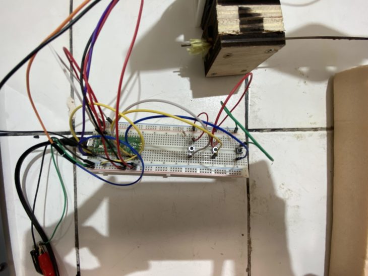
Pico Connections with buttons to simulate Digital IO signals from Robot Optocoupler
Beta_Test Cut Results


Further Development
3 Button prototype
The current prototype works on combination of three buttons to produce 8 combination angles. These combinations are on the raspberry pico.
Binary servo angle input
Further development could add up to 8 binary digits to control angles for each servo. The binary digits would be fed to the IO command from the geometry in Rhino/GH using the arc tangents of curves and converting these to the binary equivalent of the PWM pulse signal.
Python Further Development Logic
The next steps in terms of the Hardware used would be either go with a stepper motor for finer control over the rotation of the wire or stick with a servo motor and introduce a variable speed logic and gear reduction to add resolution to the curve.
Also ideally our next steps would also be to integrate grasshopper with the Raspberry Pico using a .csv file, where the .csv file gets its data from the grasshopper that can be translated to servo.angles in the python code
References
-
http://crl.ethz.ch/papers/hotwirecutter.pdf
- Resistivity: Constantan resistivity and temperature. Schlumberger Limited, 2007.
- Robertson, Ian. Electronics for Electricians and Engineers. New York, NY: Industrial Press, 1987: 34
- The State Education Department. 2006 Edition Reference Table for Physical Science Setting/Physics. Albany, New York: DOE. 2006-2007
PiCutter is a project of IAAC, Institute for Advanced Architecture of Catalonia developed at Master in Robotics and Advanced Construction in 2021 by:
Students: Christopher Booth, Mit Patel, Tomás Quijano, Vincent Verster
Faculty: Angel Muñoz, Shahar Abelson