circularThe purpose of this exercise is to learn about sustainable active systems for collective housing buildings and integrated design processes through collaboration. We worked as a team where every member was assigned a different role as lighting, plumbing and HVAC engineer, and came together to plan the systems of a timber collective housing.
Collective Housing Plans
system
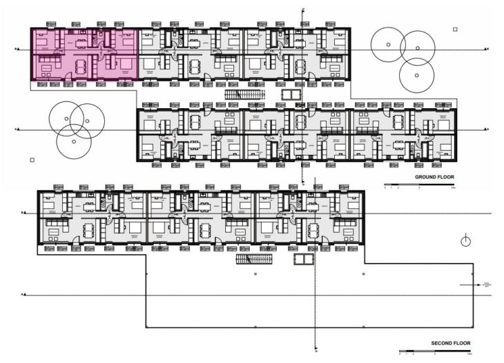
The building consists of two longitudinal blocks with 3 apartments each connected by a central corridor, which houses the staircase and elevators. There is a collective green roof on the second floor, making a total of 15 apartments. The proposed apartment layout emulates the building plan, with two longitudinal rows of rooms. The apartment is thought for a family consisting of two adults, a kid and a grandmother, and the apartment may also be used as a home office. For the exercise, we will consider the apartment highlighted in pink.
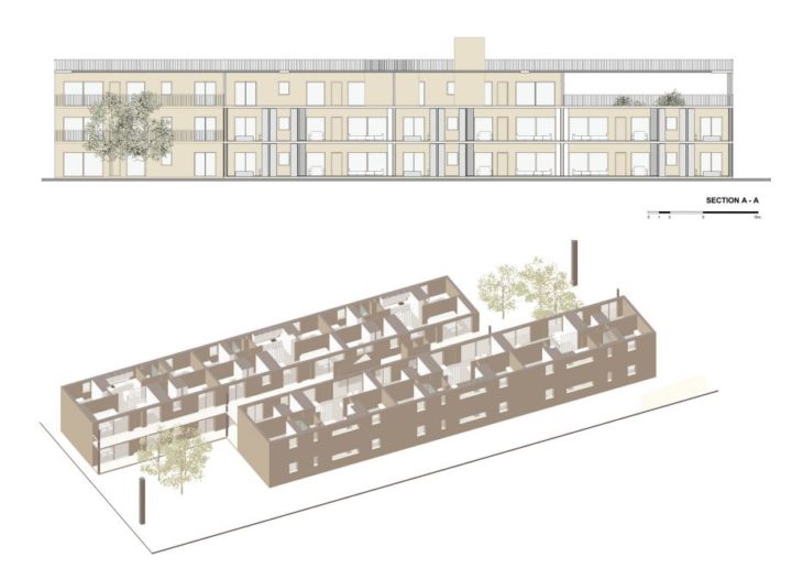
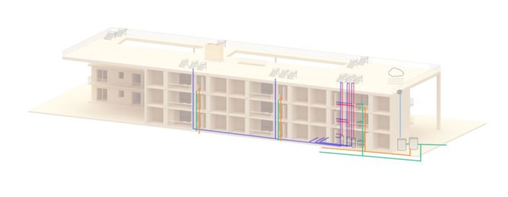
Section and Axonometric of the Housing Project
The climate conditions for this exercise are made-up so that it is impossible to rely only on passive strategies to achieve indoor comfort. Therefore, we need mechanical systems.
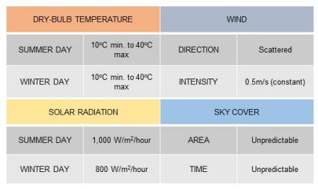
Given Climate Conditions
LIGHTNING
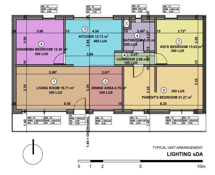
Considering the occupants of the dwelling and knowing that the apartment will be also used as home office, we need to calculate task lighting for the office areas in the bedrooms as well as for the kitchen food preparation and dining area. Light Level or Illuminance is the total luminous flux incident on a surface per unit area, and it is measured in foot candles (ftcd, fc, fcd) in the Imperial system or lux in the metric SI system. one lux = one lumen per square meter.
Dynamic Daylight Analysis
Dynamic Daylighting Analysis
Even though we are working on an imaginary geographic location with hard winter and summer conditions as well as no wind direction, to proceed with the lighting strategies, we must identify how dense the power requirements are in terms of artificial lighting for our project. In order to declare if our project has sufficient levels of daylighting, we assume that is located in Munich. We are using Andrew Marsh software called ‘‘Dynamic Daylighting’’ and introduce epw climate date file for Munich, downloaded from energy-plus website. The reason we are focusing again on this specific city is because we would like to examine the dynamic daylighting for places where there is no sufficient daylighting such in Central Europe. This will also make sense for the water rainfall and HVAC systems. In this case we calculate the illuminance threshold regarding the percentage of daylight entering in a particular space during the day, so we identify the critical points of daylight autonomy of each space to know where to put specific focus regarding the combination of different control systems. In this case, we are going to calculate each room.
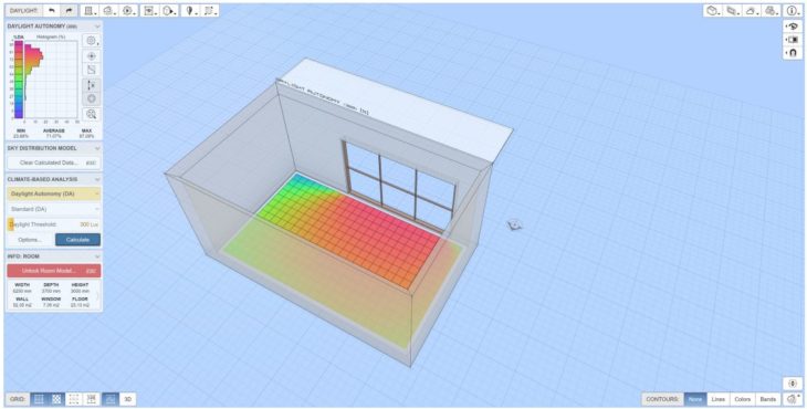
Andrew Marsh Daylight Tool
However, we should bear in mind that this is a guideline/calculation example. The actual amount of lux can always differ, for example, due to the height at which lamps are placed or the distribution of the light. In addition, the desired number of lux is also a matter of personal taste.
Then, we must specify the color temperature according to the activity of each space. In general, we choose warmer color temperature for spaces such as bedrooms and lounging areas and colder color temperature to areas that tasks are performed, such as food preparation in the kitchen, dining area and home office desks. To this extend brighter and more white color would be a good option for hygiene areas such as bathrooms.
The lighting strategy is to use task, ambient and decorative lighting depending on the activities of each room. We’ll look at technical specifications of different luminaries in the market and choose the one that best suits each area.
The result is the lighting plan for the whole apartment.
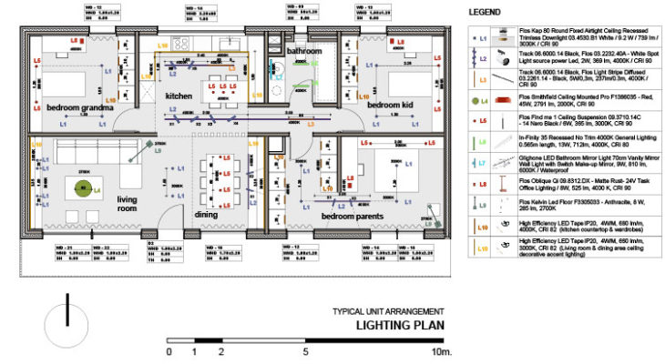
Lighting Plan
Lighting Power Density (LPD)
The lighting power density or LPD is the lighting load in watts/sq ft (or watts/ square meter). For Interior lighting power density calculation, ECBC has two approaches which are as follows:
Building Area Method Here, LPD is determined by using each appropriate building area type.
Space Function Method LPD is calculated by using each area type in a building In cases where both a common space type and building specific space type are listed, building specific space type LPD shall apply.
To convert the W/ft2 to W/m2 we must multiply the Watt/Square Feet × 10.76 = Watt/Square Meter
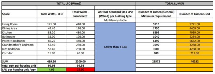
LPD Project Results compared to ASHRAE Standard
Even though the total LPD is lower than the standard, the maximum number of Lumen used are almost 25% more than the minimum requirement. In our proposal, we use plenty of luminaire’s typologies for all spaces and to use less energy according to ASHRAE standard 90.1 we use BMS control systems where sensors will manage the lighting density as well as will turn on and off the luminaires according to each space requirements and natural daylighting autonomy. For this purpose, we must introduce motion/occupancy & daylighting sensors to achieve the highest performance of LED by reducing the energy consumption up to 30%. The sensors will be connected to the preselected luminaires and the dimmable Bluetooth switches to a central BMS control system. Regarding the table above, we choose LED instead of incandescent luminaires not only because they are more efficient as they offer 4 times reduced power but also because the energy load of the HVAC system is reduced regarding the internal heat gains. For the same reason, we consider BMS control system as the best option to integrate lighting, HVAC and fire safety.
This system is integrated to the apartment plan.
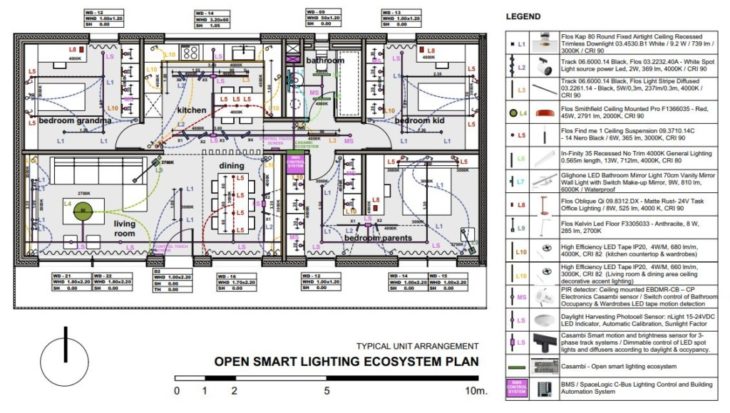
Integrated BMS System
So, the reason we introduce control systems is to combine the natural daylight and artificial lighting in an efficient way to consume less energy while maintain the optimal lighting strategy according to the following key factors:
- Adequate lighting levels
- Low glare
- Luminance distribution
- High CRI
- Appropriate color temperature for each space
- Light direction
In our proposal there are two families of control systems. Motion sensors – in bathrooms lights are turned on/off when someone enters/leaves by saving10-30% of energy. Dimmable sensors are a combination of daylight sensors that lead to central control system and regulate the amount of light of the interior spaces according to natural light. For lighting performance design we had to specify the control systems as it would be very cost effective. In this case, control systems were identified such as:
- Manual controls
- Sensors (occupancy in wardrobe, presence, absence)
- Lighting control modules
- Network components
- Central supervisors
- Lighting management software
- Building safety / efficiency protocols, such as Photovoltaic cells on facades windows that activate and alarm the control system when there is daylighting to turn on or off the lighting devices.
BMS (Building Management System) is the brain of the building. It includes, artificial lighting, heating -ventilation and air-conditioning (HVAC), firesafety, motion detecton, CCTV, mechanical shading devices.
WATER MANAGEMENT AND PLUMBING ENGINEERING
We consider our apartment layouts to determine where we will need access to water. We have one bathroom per housing unit and the kitchen with some appliances such as dishwasher and washing machine. We create a shaft between the kitchen and the bathroom where we’ll place the pipes. We’ll also consider the different activities of the occupants to calculate their water consumption needs.
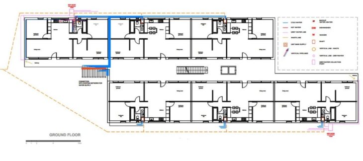
Water Supply System Plan
The main supply system is in the middle of the building to get shorter pipes that will serve all the apartments. For each side of the block, we have a waste pipe that will collect black waters and with inclination will lead them to the main collector and to the city network.
We also use a greywater collection system, and we place two collectors one to each long side of the building which will serve all the dwellings.
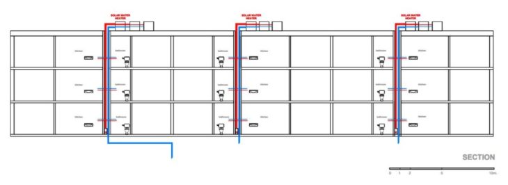
Section of the Water System
When we go into detail for each apartment, it is important to understand that in the same shaft we have the pipes for warm and cold water for the bathroom and kitchen appliances, the waste tube and the greywater collection pipe that serve all the apartments vertically. The greywater collection tubes are connected to the main greywater collection point distributing to the plumbing system. We also collect the greywater from the balcony.
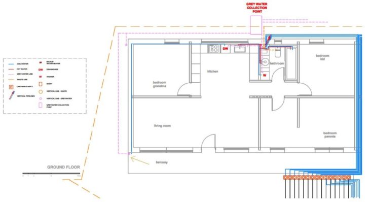
Water Supply of a Single Apartment
The system is connected to solar panels placed on the roof to heat the water. Each apartment will have its own solar heater. In the rooftop plan we can see the solar cells as well as the rainwater collection points. Rainwater will be also integrated in the system, taking advantage of the big roof surface we have.
Considering the water saving strategy we take into consideration again real climate data from Munich to see how our system would work in such weather, and to see if rainwater collection would satisfy the needs of our users. We use different tools such as Meteoblue to make the calculations to see how many liters we could get from rainwater. The rainwater could be combined with the greywaters to get a sustainable circular model for the water cycle.
Overal Scheme of the Sustainable Circular Water System
To concretize our proposal and be able to calculate water consumption, we choose different fixtures with low water consumption and consider different scenarios, from which we can get some conclusions:
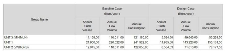
Table showing the different calculation results
1) With the assumption that 2 people are “residents” (being full time at home) and 2 “visitors” (UNIT 2 VISITORS), the annual water consumption is almost half of the option with 4 “residents“ (UNIT 1).
2) When using fixtures with max efficiency (UNIT 3 MINIMUN) you can reduce an important amount of the water consumption per unit.
3) With the example of a rainy climate (in this case Munich) and the annual rainwater collection of 901,666 liters it can be considered that some important needs for water use are being covered (for bathroom & kitchen faucets, toilets, showerhead), together with the option of using fixtures of max efficiency (UNIT 3 MINIMUM). For this amount of rainwater that can be collected, big catchment area of the building plays an important role.
4) In total combining the aforementioned strategies with a grey water collection system for the washers (washing machine, dishwasher), the water consumption of the units can be reduced significantly.
5) The current housing configuration, with baths and kitchens positions, together with the position of the main supply area on the ground floor can help to have an efficient pipe system with small lengths in the horizontal direction.
HVAC SYSTEM
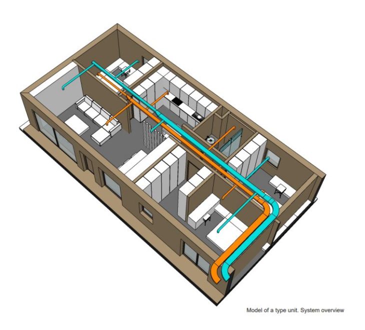
3D view of the HVAC ductwork
The last active system studied is HVAC. Two aspects that will inform our design are the climate conditions and the inhabitants of our housing unit. The former are such that we cannot rely on natural ventilation, and we’ll need a mechanical ventilation system. As for the occupants, knowing the activities they will realize in the apartment lets us estimate the indoor thermal comfort temperatures that our HVAC system will need to provide. Considering the metabolic rate of the inhabitants while realizing different activities can also be useful to estimate the thermal comfort. To do this, we will use the CBE thermal comfort tool, which is based on ASHRAE Standard 55.
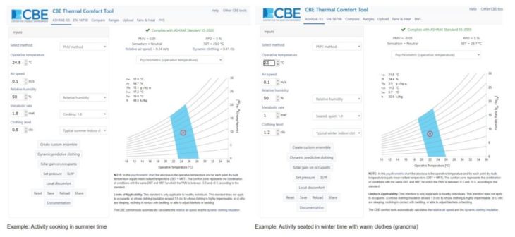
Results from the CBE Thermal Comfort Tool
Thermal comfort estimates have been done for every room in the apartment to have an idea of which temperature range the HVAC system should provide in summer and in winter, and we get that the indoor thermal comfort in summer will be between 22 and 29 degrees, and in winter 18 to 27 degrees. We also look at ASHRAE Standard 62-2001 to see which outdoor air flow rate should be provided, in this case it would be about 7,5 dm3/s /person. So, if we know how many people will use a room at the same time, we can estimate an air flow rate. That will help us in the choice of the air handling unit (AHU)
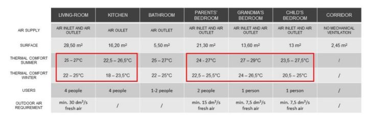
Table with the requirements for each room
The overall strategy for the HVAC system is the use of a single air handling unit with heat recovery system placed on the roof of the building. The building design with the open terrace on the second-floor lead to the creation of a shaft close to the stairs. In this way, the rooftop unit is not directly above any apartment, which could cause noise problems. The supply and exhaust air ducts would go through this vertical shaft and then divide into a branch for each apartment. The layout for each apartment would change slightly to get shorter ducts. And here we see a longitudinal section. All ducts would be placed above a drop ceiling.
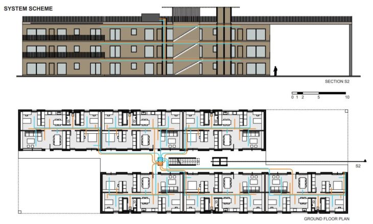
Floor plan and longitudinal section of the housing block
All rooms have inlets and outlets, except for the kitchen and bathroom that would only have air extraction. The living-room has two inlets for supply air due to its longitudinal dimensions and to the fact that we have an open kitchen, that could also need some fresh air supply. Each room would have its own thermostat due to the different needs of thermal comfort for every inhabitant, and another thermostat would be placed in the living room.
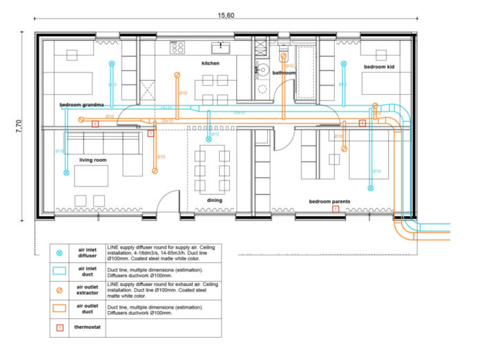
Single Unit Ductwork Plan
In the ductwork plan we have assigned different estimate dimensions to the air ducts, considering that they will get narrower towards the end. We have chosen a model of diffuser that can be used for both air extraction and supply, in this case it is a rounded ceiling diffuser of around 20cm, and the ducts linked to it have a 10cm diameter. The different diffusers have been placed in the rooms to achieve air circulation and avoid air stagnation in winter. The layout of the apartment has also been considered, for example that no user would have an air supply directly onto her head.
From the diffuser’s technical sheets, we can estimate the throw of our diffusers, and therefore the air circulation in every room. With the placement that we have chosen for the air inlets and outlets, we think that we can get a good air circulation and minimize air stagnation in wintertime.
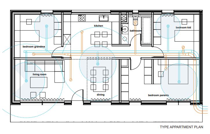
Single unit plan showing the diffuser’s throw range
This exercise gave us an overview of a building’s active systems and got us to understand the needs of its inhabitants to get to comfort conditions. We could also get into more detail to which choices lead to a sustainable building, and had to collaborate to make the systems work together and make some critical decisions such as the placement of the shafts to coordinate lighting, water management and HVAC.
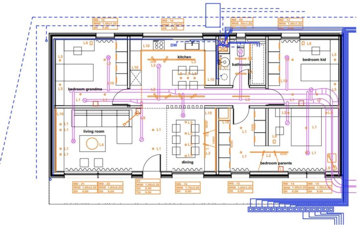
Overlay of the three active systems studied
Useful links:
Andrew Marsh Dynamic Daylight Analysis
http://andrewmarsh.com/software/daylight-box-web/
CBE Thermal Comfort Tool
https://comfort.cbe.berkeley.edu/
Performance Design Strategies for a Mass Timber Co-Housing is a project of IaaC, Institute for Advanced Architecture of Catalonia developed at Master in Mass Timber Design in 2021/2022 by Students: Alexandros Kitriniaris, Eirini Doumani Korka, Maria Cotela Dalmau. Faculty: Patrick Spencer. Course: Techniques 2.2