In this blogpost we will show you our explorations regarding studio, designing pavillion and bridge structures. In these attempts structures have been firstly analysed as shells, comparing regular grids to options derived from force flow.
Pavillion Analysis
Our pavilion consists of a repetition of simple elements that twist, bend and rotate to create an organic geometry. We will study and compare the generation of the pavilion through two different sections; a triangular and a rectangular one. For both, we start analysing the repeated element and the overall geometry in order to conclude in several proposals.
a. Triangular Section
Option A
Geometric Analysis
Analysed Compositions
We analysed several compositions in Karamba and as expected compositions with fanned elements behave better. Fanned compositions increase overall stability because the moment frames are repeated in a different direction than the longitudinal wind direction.
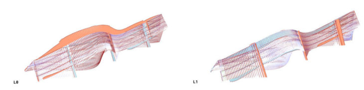
In order to understand how the structure works and which parts of it receive the most stresses, we start by analysing the structure as a shell.
Shell Analysis
We conclude that the angle of inclination of the elements is decisive, where elements that are more inclined towards the ground lean on the other elements. This is further proved by the differences in reaction forces at the supports.
Pavillion section
The most inclined surface would be the most appropriate place for making an opening.
Pavillion Options
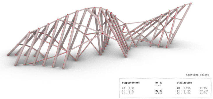
Repetitive elements
The first option consists of a repetition of wooden columns, linked by steel elements and cantilevered elements further braced by arches.
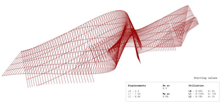
Axial forces
Few elements take the most stress. Through assigning different cross-sections a optimized structure can be achieved.
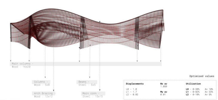
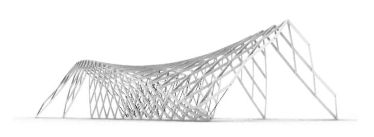
Final Option
Stress lines grid
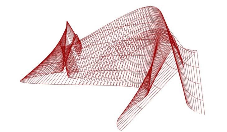
Through the shell stress lines we observe that forces flow in a arch like manner. They help us to better understand how the structure works, placing elements along axial forces, in order to avoid bending. Wooden columns are placed along force flow, and further steel elements are proposed to hold the structure together.
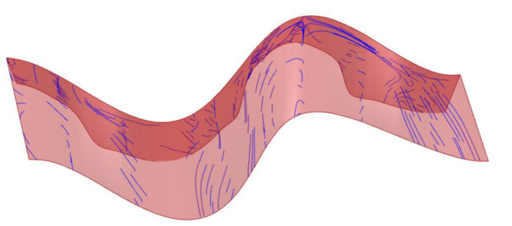
Shell force flow
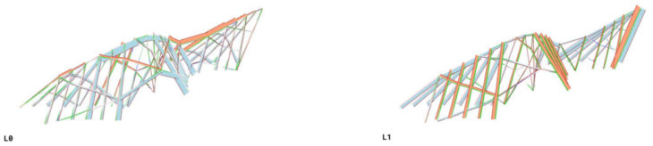
Axial forces
We observe that unlike the first option, forces are now well dispersed uniformly along the structure. Starting displacement values are also optimal.
Although this alternative uses materials more efficiently since the placement of the elements follows the overall geometry, both structures are relevant.
b. Rectangular Section
Geometric Analysis
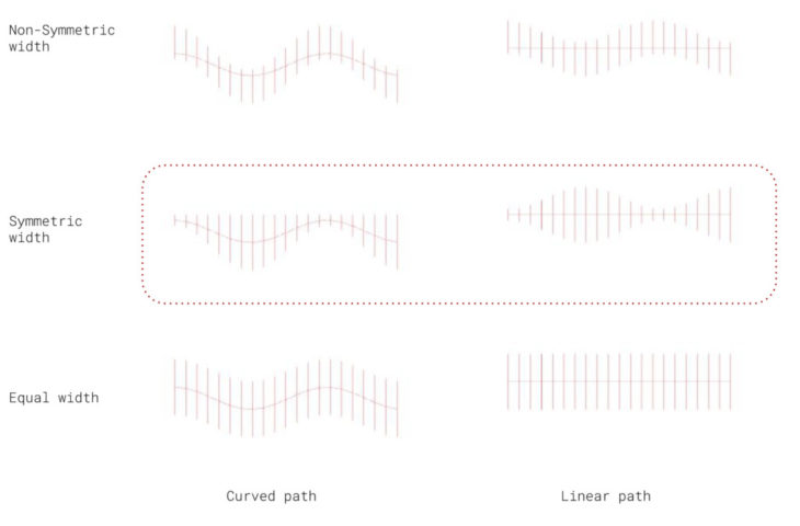
After the analysis of several sections with Karamba, we cannot observe a pattern that defines an option with a clearly better performance, although we can conclude that proposals that follow a curved path have in general a better behavior facing lateral loads.
In addition, non-symmetric width proposals have resulted the two most balanced options in average against all load cases, so we will continue our analysis considering them.
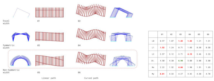
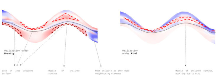
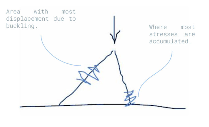
We start analysing the structure as a shell to highlight where are located the areas less stressed. Both against horizontal and vertical loads, the greatest utilization of the structure occurs in the shortest elements of each section; not because of its length, but because its position against the main stress.
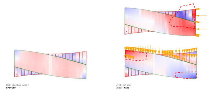
As shown in the diagram, the interruption that occurs in the transmission of the loads to the supports must be completely counteracted by the element perpendicular to the main stress. The utilization will be gradually reduced until that element reaches a 90º angle with the ground. From this point on, the same equal and opposite effect will begin to occur at the other end of the section.
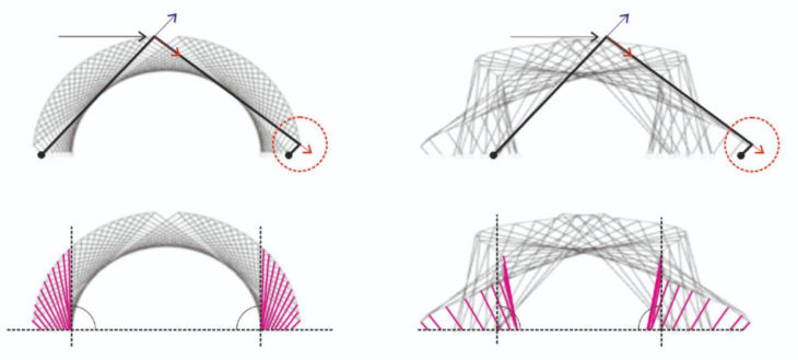
Therefore, these critical areas will be properly stiffened to help to counteract the efforts and optimize the structure.
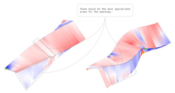
For the same reason indicated above, the elements of the section that transmit the stresses directly to the supports are those that present lower utilization, and are therefore the areas indicated to plan openings in the structure.
Pavillion Options
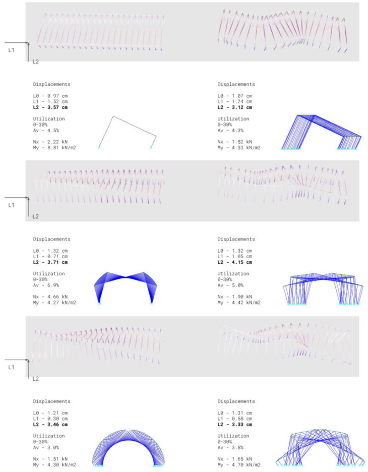
0. Initial setup
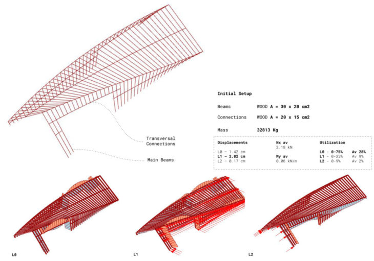
The first option consists of a repetition of wooden columns linked by wooden elements. Highest Utilization occurs under gravity (L0), which means the structure is too heavy for the loads it is facing. Also, local stresses are evident around the openings, while other elements are practically not working, which makes clear for us where should we increase and reduce the cross section of the structure to balance the forces.
1. Repetitive elements
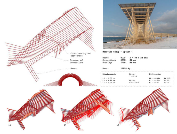
For the second option the connections and the added bracings are made of steel. Again, highest utilization occurs under gravity (L0), which means the structure is too heavy for the loads it is facing. Although we have optimized the cross section of the elements, reducing considerably the total mass of the structure, some elements still reveal themselves to be underused.
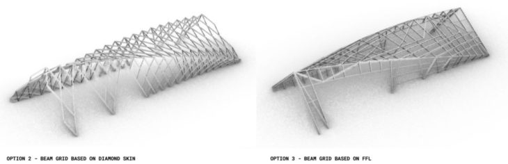
2. Diamond skin
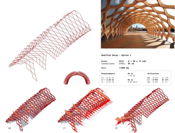
This option, that simulates a diamond skin, has 1/3 of the self-weight of the previous versions, and its elements reveal themselves to be working as an assembly, as the efforts appear in a more homogeneous way.
3. Stress lines grid
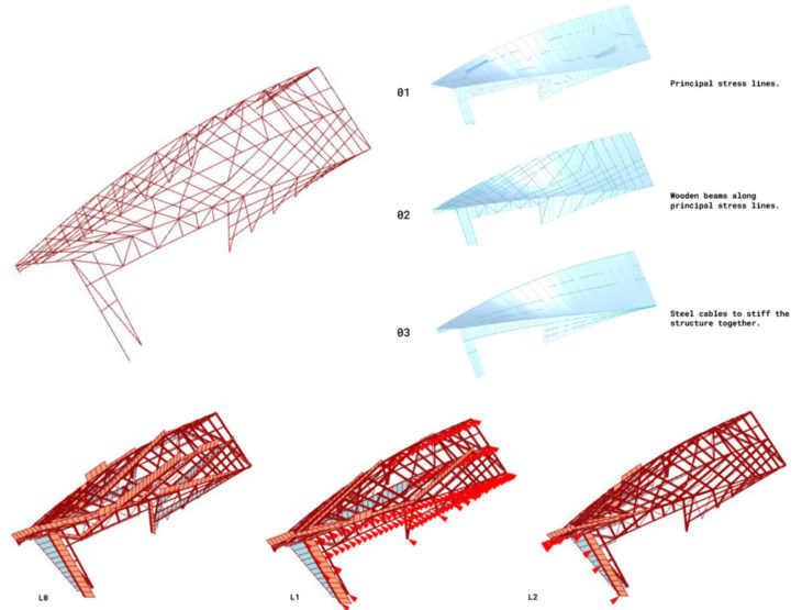
Finally, we tried a design that follows the principle stress lines of the structure as a shell, obtaining a more random grid pattern that, although reduces the self-weight of the initial setup, is still far away from the values we got in the previous version.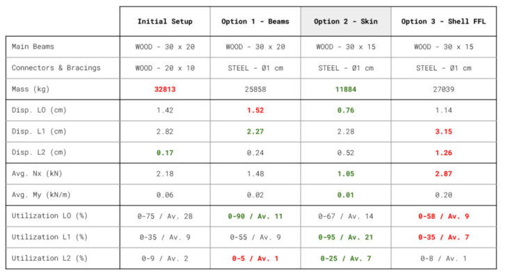
After the analysis of different proposals for our rectangular section pavilion, we conclude that the beam grid version that imitates a diamond skin (Option 2) is the most efficient one, having only one third of the weight of the other options and still showing the most optimised values for displacements and utilization in many cases. Its design proves to be very efficient against horizontal loads, as the diagonal beams act as bracings, generating a very strong stability system that also, as a plus, can be standardised.
It is obvious that the version based on the shell forceflow lines could have still been considerably optimised to improve its lateral stability, but it requires a much more detailed study for it. The heterogeneity of its design demands to carefully analyse the different cross section of its elements, which also avoid the standardisation of the beams and therefore increases the cost of the structure.
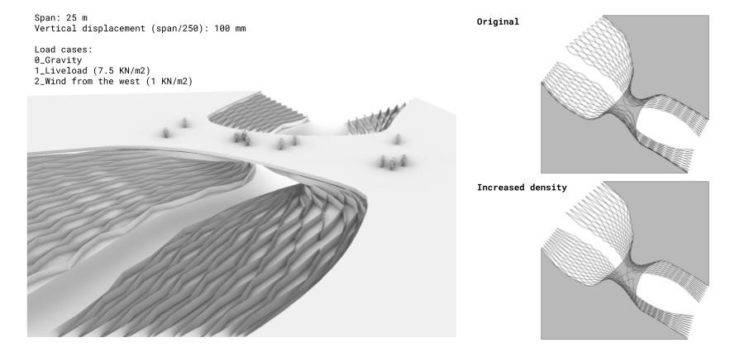
Bridges Analysis
For designing the bridges we have followed two different approaches:
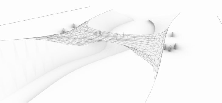
1 – The first one starts from the local elements on the design system, the lattice, and tries to morph them into a bridge that will allow people to cross the canal.
2 – The second one works with the bridge geometry and searches for the best shell structure to span along the canal following a geometrical optimisation process.
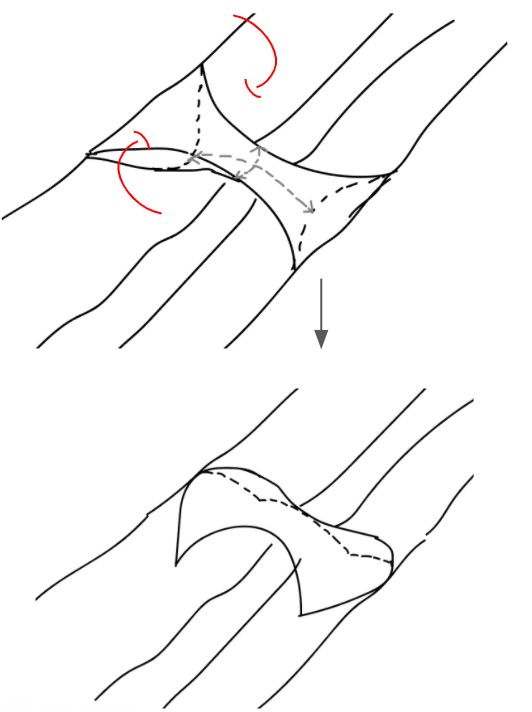
Approach 01
On the first approach, the first step is to concentrate material below the bridge to make it more stable. The first iteration connects both sides of the lattice without including any new elements.
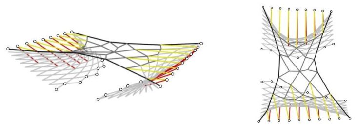
The most stressed elements are the edge beams and the elements in the middle, as they are the most direct path the loads have to the supports. There are high stresses and large cross sections close to the supports and displacements due to liveload and deadload are close. All this tells us that the base geometry is weak.
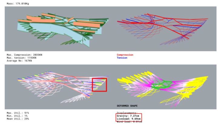
The weakest area is the lattice located underneath. It lacks bracing and hence the capacity to hold the bridge in place increasing deformation and stresses close to supports.
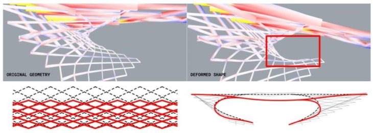
Understanding these issues, the next iteration braces the lattices placing longitudinal elements that allow a better structural performance.
This new family of elements has a direct implication not only in load bearing capabilities but also in weight reduction. Maximum normal values decrease while the average increases which means a higher utilization while reducing punctual stresses. This new bracing elements are now the most direct path for loads to reach the support and the will undergo higher stresses in general becoming the key structural family in this configuration.
Average utilisation increases and the lattice elements underneath are more stressed than in the previous configuration as the bracing transfer loads to them. Deadload displacement is much lower than the liveload one as the bracing increases geometrical stiffness.
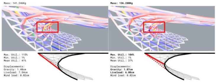
The most stressed points are now in the places of high curvature underneath the bridge. To reduce the curvature effect, placing a connection to the supports in the areas of higher curvature made a major impact in weight and displacement.
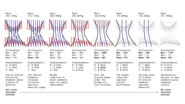
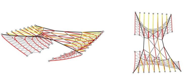
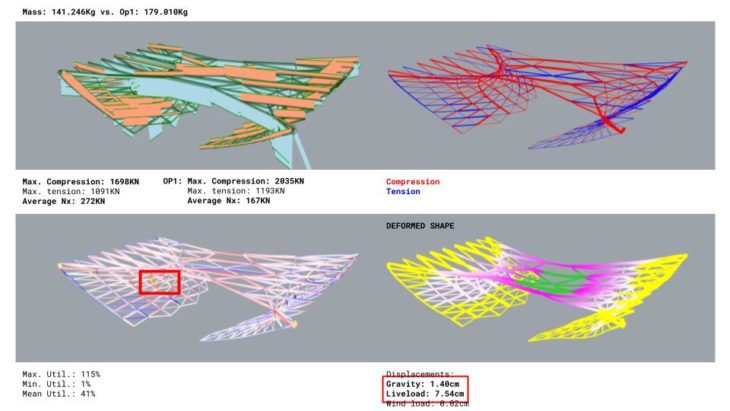
Understanding the complexity of having a completely unstandardised structure, we looked for the elements that would benefit the most from having bespoke cross-sections. Mainly these are the ones that go from side to side and carry most of the loads and the numerous ones that are loaded only locally.
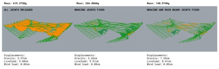
To finish, we studied bending moments to understand the key elements whose joints should be rigid, which are the main beams that would work as a single beam going side to side and the over-stressed bracing elements.
Approach 02
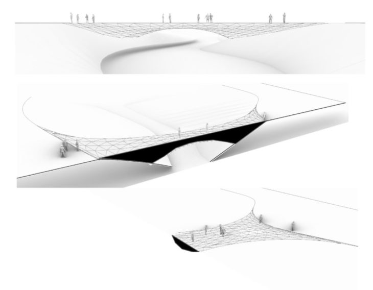
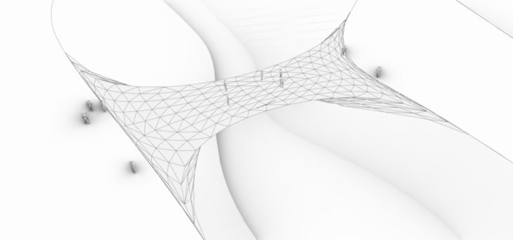
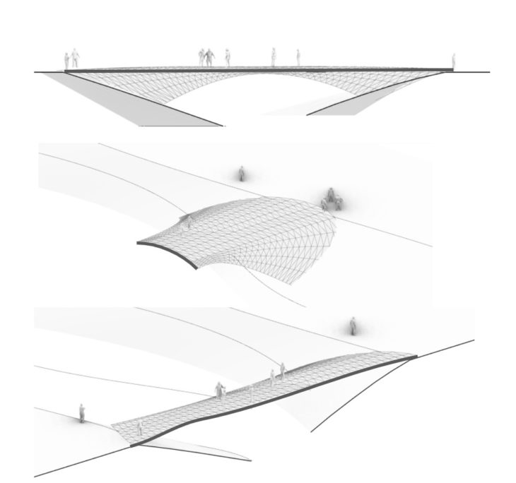
In this second approach, we wanted to explore the effects of geometry on structural performance by studying a doubly-curved bridge structure. We examined the 300mm deep concrete shell structure(s) under dead and live loads to observe structural behaviours and proceeded to optimise this geometry computationally and manually to improve the displacement and utilisation values in the respective loadcases.
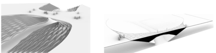
Option 1 Geometry
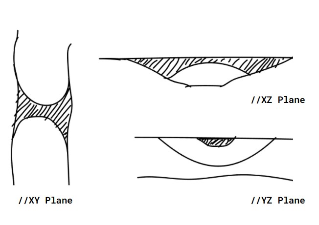
Our initial idea aimed to connect the landscape with a curved structure that grows organically from it. We developed a doubly-curved hollow shell; the geometry is bent in three planes; XY, YZ and XZ planes. With this geometry, we ran some initial analysis to check deflection and utilisation for three loadcases (0 – self-weight, 1 – live loads, and 2 – wind loads) and to see how the top and bottom components of the shell will behave. For the sake of clarity, we will call this geometry Option 1
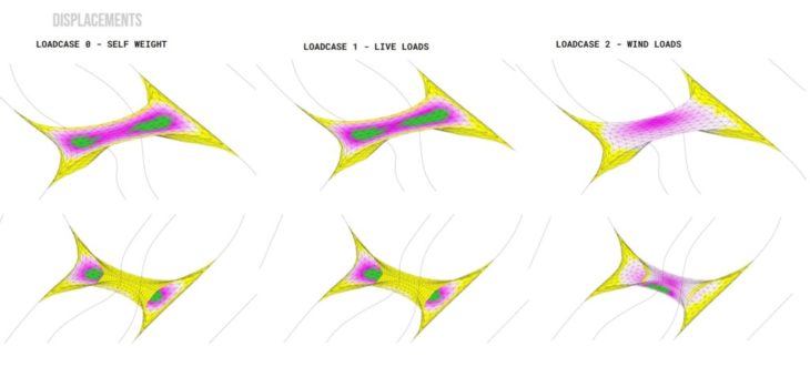
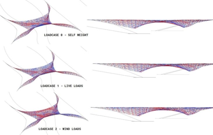
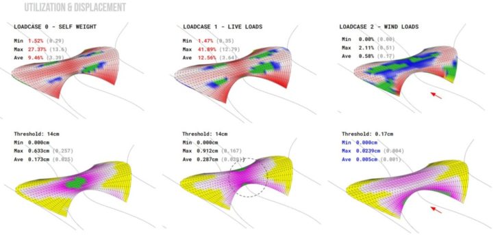
Option 1 – Displacement for different loadcases
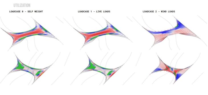
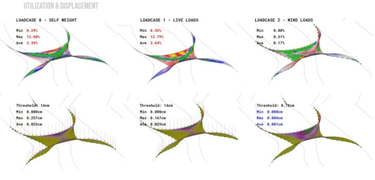
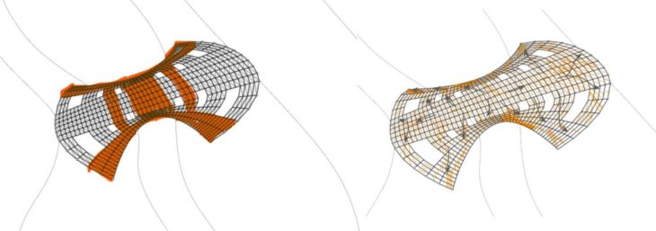
Option 1 – Utilisation for different loadcases
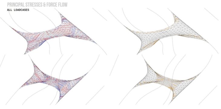
Option 1 – Principal Stress and Force Flow Diagram for all loadcases
From the displacement maps, it was evident that deflection was maximum in the middle of the top shell for spans larger than 6.5m in the vertical loadcases (0-self weight and 1 – live loads) because the shell is hollow. In the utilisation map, it appeared that the bottom shell was not bearing any of the loads in loadcases 0 and 1, signalling that the void reduces effective transmission of loads, and infill material is needed to bridge the load transfer. However, the lower shell showed more usage in resistance to lateral wind loads. While it appears to not bear any load for the vertical loadcases, the force flow and principal stress diagrams indicate that forces do travel through the lower shell; therefore, we chose to study the lower shell separately to understand its behaviour.
Option 1_Lower Shell – Utilisation and Displacement for different loadcases
Option 1_Lower Shell – Principal Stresses for different loadcases
Viewing the displacement and utilisation for the lower shell, we see maximum utilisation, concentrated in an x-pattern, suggestive of areas of reinforcement or material concentration for optimisation. Principal stresses also indicate arch-like compressions in 3-Dimension. Reduced displacement values in this structure for all loadcases indicated that the lower shell is much more effective on its own.
Option 2 Geometry
Given that the lower shell is much more structurally effective and also to have a walkable surface for the bridge, we flipped the lower shell geometry to create and adapted it to fit within the landscape while keeping the curvature in 3 planes. This new geometry = Option 2
Option 2 – Utilisation and Displacement for different loadcases
With Option 2, we see improved, more distributed utilisation – Average utilisation values increased for all loadcases, indicating a better load distribution within the geometry. While displacement values increased, they were below the thresholds for the bridge span. Higher displacements at the edges in the live load cases may indicate that the side arches should be thicker than the rest of the structure.
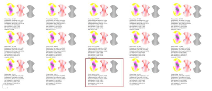
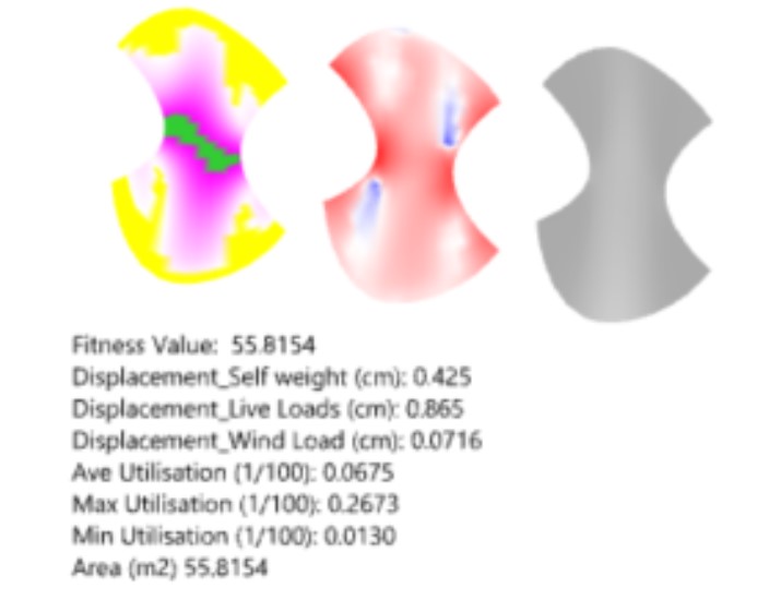
Option 2 – Optimisation
We chose to computationally optimise this geometry, adjusting the dimensions (bridge span, width and structural depth) and consequently its proportions, to derive a geometry that performs better in terms of displacement and utilisation. From the evolutionary solver analysis, we extracted the best 15 iterations from which we selected one that gave the minimal total deflection for all loadcases. This optimised geometry = Option 2B
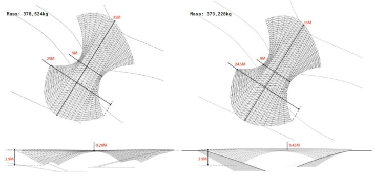
Option 2_Option 2B Dimension Comparison
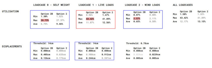
Option 2 _Option 2B Values Comparison
Subsequently, we compared values for utilisation and displacement for Option 2 and Option 2B. Geometrically, the span and width values are similar; however, option 2B has a higher structural depth than option 1, and we believe this increased depth helped improve its performance against the vertical load cases. From the table above, we note slight variations in utilisation values and a reduction in average displacement for all loadcases. More importantly, both options show higher utilisation values for self-weight and live loadcases than for the lateral wind loads, indicating that the structure works more to maintain its weight than it is resisting external forces. Therefore, further manual optimisation (by cross-section variation and material removal) will be required.
Option 2B Analyses
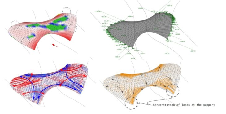
For further (manual) optimisation, we studied the principal stresses and force flow diagrams of Option 2B. There are compressive arches following the curvature of the shell, and they are being held together by tensile stresses. The force flow diagram shows that loads are spread to the edge arches and towards the lower support areas. The reaction forces diagram validates this observation.
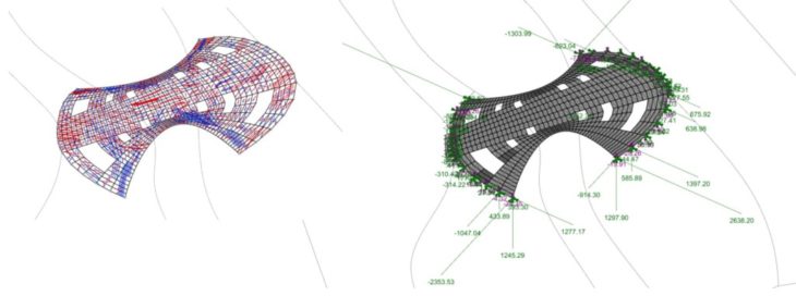
Option 2B – Optimised; Top Left – Material Removal & Thickening, Top Right – New Force Flow, Bottom Left – New Principal Stresses, Bottom Right – New Reaction Forces
We thickened/added materials along the compressive principal stress lines and force flow (420mm thick along these lines and 120mm thick in the rest of the structure). This strategy helped to reduce the overall mass. We also added holes in areas with the least utilisation values. The resultant geometry (now Option 2B-optimised) shows a similar force flow to Option 2B, going from the centre towards the corners, and the reaction forces show that loads are still channelled to the corner support points following the force flow lines. However, we see redistributed principal stresses around the holes.
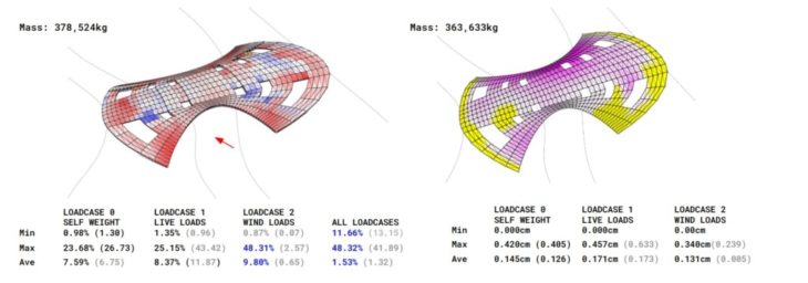
Option 2B Optimised – Utilisation and Displacement Diagram and Values
The resultant geometry (now Option 2B-optimised) shows considerable improvement in utilisation values. Here, maximum and average utilisation for loadcases 0 and 1 dropped significantly (50% reduction for loadcase 0 and 15% reduction for loadcase 1). More importantly, we saw a massive increase in maximum and average utilisation for loadcase 2 (1900% increase in values compared to option 2B). This improvement we noticed after punching the holes in the geometry. While the displacement value for this loadcase increased, it was still far less than the threshold for this bridge depth. The redistribution of shell cross-section to areas of high compression stresses also helped reduce displacements for live loads.
In conclusion, we found that the slightest changes to geometric proportions have implications for structural performance. We also identified structural depth as one of the most critical dimensions to consider when designing. Varying material thicknesses and distribution also have notable impacts on structural behaviour under different load types. Additionally, while this exploration only sought to optimise the geometry by removal of materials and thickening cross-section, we think using the principal stresses to create a beam grid supporting a thinner surface shell may produce similar or better outcomes and could be worth considering for further analysis.
In the end, comparing the two bridge design approaches, one workflow starting with the global geometry and the other delving into the beam grid design directly, both have their merits to tackle structural design. It was interesting seeing that irrespective of how we approached the design, optimisation involved a manual process of material and cross-section distribution, and both hinged on reading and understanding analysis and structural behaviours.
CREDITS
Grid and Gridshell structural explorations is a project of IAAC, Institute for Advanced Architecture of Catalonia developed in the Master In Advanced Computation For Architecture & Design 2021/2022 by Students: Erida Bendo, Lucía Leva, Pablo Antuña and Oluwadamilola Akinniyi; Faculty: Manja van de Worp and Matthew Gabe