BRIEF
This assignment aims to decode the logic of the following façade system through a process of analysis and definition of the computational design behind the project. The project decoded here is a brick labyrinth garden located in Wujiazhuang Village (Dingfangshui, Xiahuayuan, Zhangjiako) and designed by Tsinghua University (School of Architecture) and Joint Research Center for Digital Architecture (JCDA) led by Professor Xu Weiguo invented the “Automatic Masonry System by Robotic Arms”.
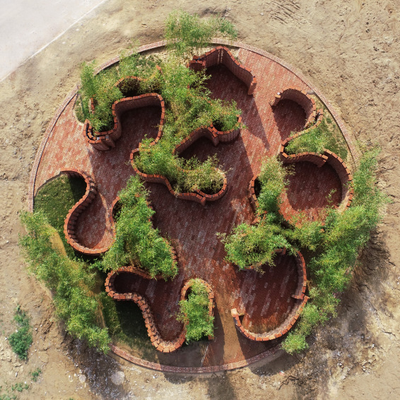

Images: runawaycow, V. (2018). A brick labyrinth garden by robotic construction. [online] Luo Dan’s Archive.
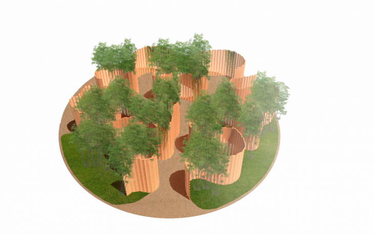
PSEUDO CODE FOR THE PARAMETRIC PARK :
1. Use curve command on rhino to trace the three brick walls from the plan view of the park.
2. Use command “loft” to make a surface for each wall.
3. Rebuild the surface to point count 30 iso curves.
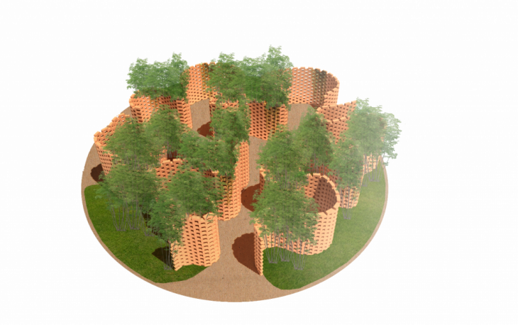
4. To import the surfaces from rhino create a “surface” component and set each individually.
5. Create a “domain box” to define the brick to be used for the wall.
6. Create a “slider” for both x,y and z inputs, this will determinate the parameters of the brick using x for the length, y for the with and z for the depth.
7. Create a “counter” component to orientate the brick on the surface and define the brick sections on the surface.
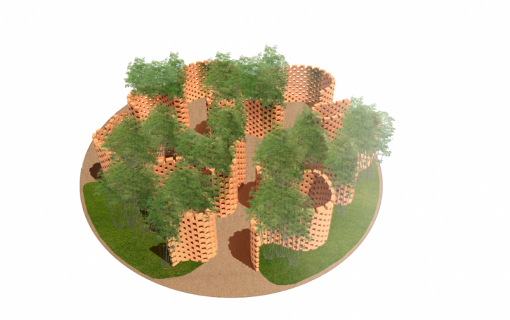
8. Add the surface required to the “shape” input.
9. Set the “point” to start from 0,0,0.
10. Add a “unit Z” direction.
11. Set the distance to the same “Z” input as the “domain box” component. This defines a null distance between each brick.
12. Connect a “curve” and flatten this output to obtain the planes as curves.
13. Use the “dispatch” tool to divide the planes into creating a pattern which will define the distribution of the bricks for each curve.
14. Create a “curve” for each list.
15. Add an “horizontal frame” to each curve to create the frame for each brick.
16. Create a common “slider” to define the count of bricks for the horizontal curves.
17. “Dispatch” both horizontal frames and create one plane for each list A and list B, in order to show the true or false criteria from the “counter” component added previously.
18. Create a common “plane” for the last two.
19. In order to define the brick to be used, connect the initial “domain box” to an “orient” component.
20. The “geometry” of the orient will be the “domain box” (brick).
21. The “source” will be the XY surface of the brick calculated connecting a “deconstruct” component and a “list item” which can identify each surface while connecting a “slider” to the “index”.
22. Create an “area” component to extract the center of this surface.
23. Connect the area to an “XY plane” to define the starting plane for the orientation of the bricks.
24. Add the final “plane” previously created to the “target” input in the “orient” component.
25. Copy and paste the process to each surface of the park.
Computational Design //Assignment 1// IaaC, Institute for Advanced Architecture of Catalonia
Developed at Master in Advanced Architecture in 2018 by:
Student: Sofia Madeira
Faculty: Rodrigo Aguirre, David Andres Leon
Assistant: Daniil Koshelyuk
