The Case Study – Module C, Generate Architects
Module C is Boston’s first ground-up full Cross-Laminated-Timber (CLT) Passive House demonstration project. Comprised of 14 residential units and an innovative pilot affordable co-working space for the local community on the ground floor. The building is entirely comprised of CLT and features a CLT rooftop canopy to mount solar panels. It also features modular bathroom pods prefabricated off site that can be hoisted and easily plugged into the building, further compressing the project schedule and reducing construction waste. The building operates at a net-zero carbon level as they are passive house certified and built to the new Boston Department of Neighborhood Development “Zero Emissions Standards”.
The aim of this subject is to deliver an accurate structural system analysis, highlighting its bracing concept, fire resistance requirements, timber deck, beams and wall construction.
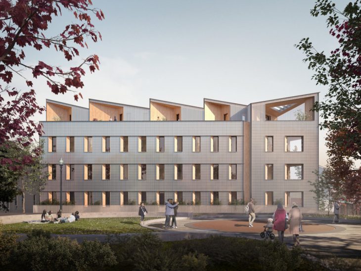
Render view of the mass timber structure . Image from Generate Architects website.
Construction Process
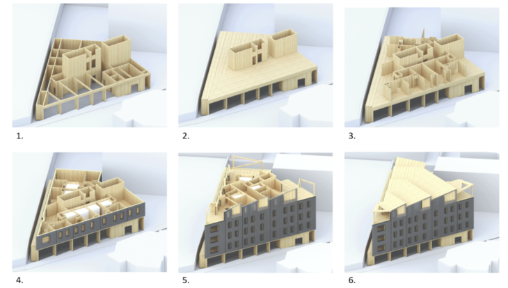
- Ground floor CLT walls are installed including stair and lift cores. Beams are placed spanning between the core and external structure.
- CLT floor panels are lifted into place parallel to the core directions. The beams rest on top of the beams and structural internal walls.
- Internal CLT walls for the next floor are then installed.
- Internal modular bathroom units are then lifted into position and the external façade is installed. This process is repeated from floors 1-3 before the CLT roof is lifted into place.
- Penthouse apartment walls and bathrooms are installed.
- The pitched roof and additional structure is installed.
Bracing Concept
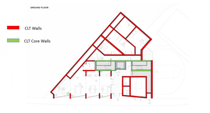
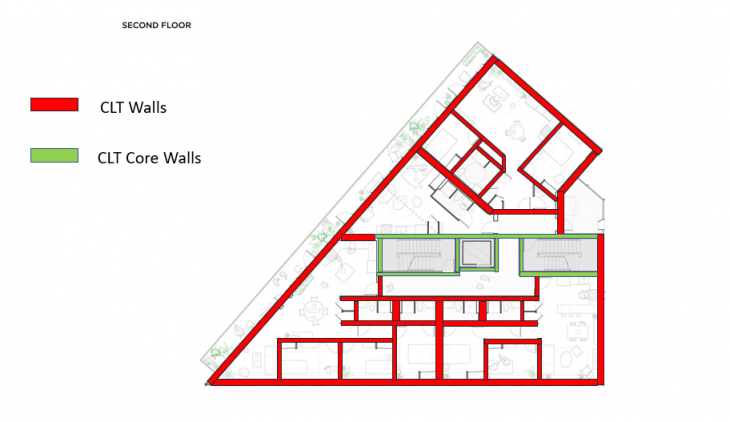
The structure is made up entirely of CLT. The exterior and interior walls are constructed utilizing CLT and support the floor structure from above as well as bracing the structure. CLT is also used to construct both the stair and lift cores. These are located in the center of the structure to anchor it down.
Floor Panel Spanning Direction
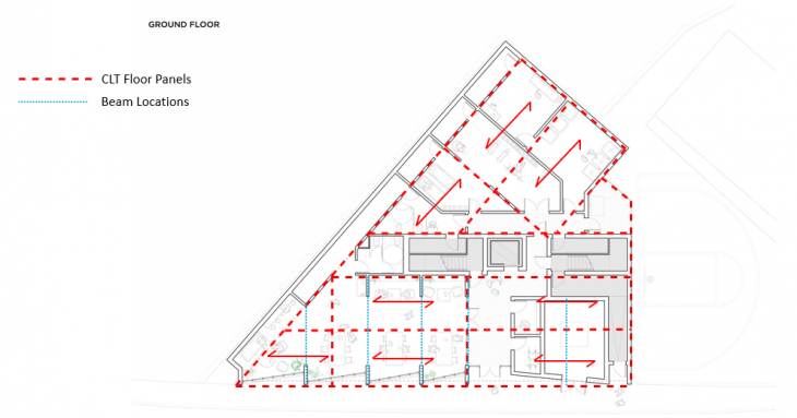
The CLT floor panels are laid on top of the CLT walls and beams and orientated in two directions. When all the floor panels are fixed in place, the walls and beams for the next floors are installed and the building continues to rise.
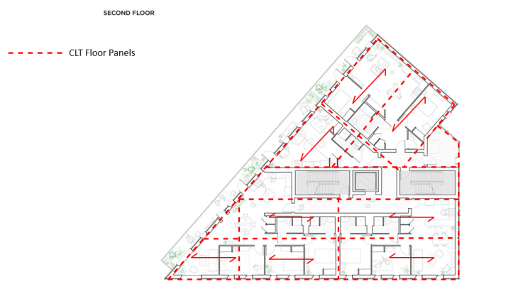
The floor panels span the same direction on the first to third floors and rest on top of the supporting beams and are connected to the lift and stair cores.
Fire Protection
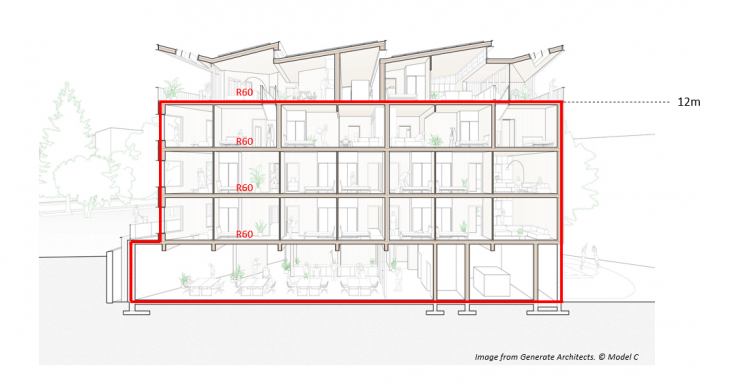
The buildings height and livable floors designate that the project in question is classed as building class 4 for fire requirements. The walls are specified as R60 fire protection to offer occupants the best chance to escape if required.
Dataholz – Calculations
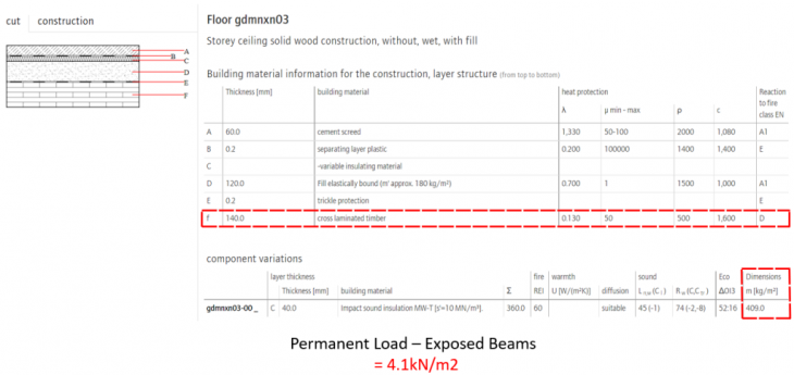
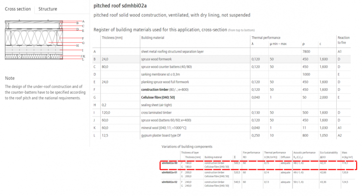
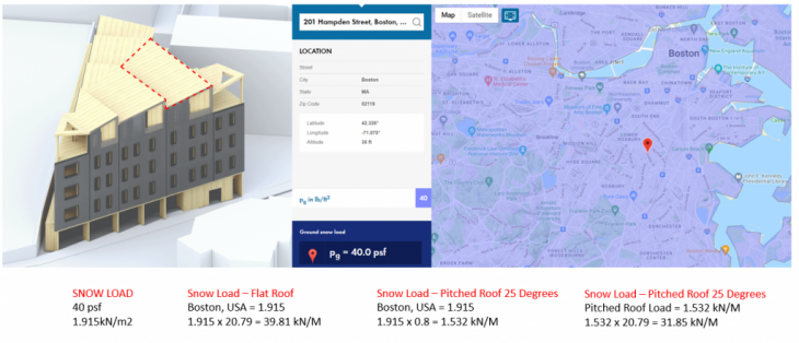
By utilizing Dataholz, we can accurately analyze mass timber products on the current designs. A CLT deck with a permanent load of 4.1 kN/m2 was chosen along with a mass timber roof deck. As the project being analyzed is in Boston in the United States , there is the potential for high snow loads, and so this must be incorporated into the analysis.
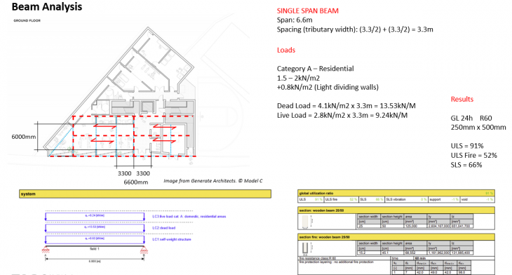
Beam Analysis
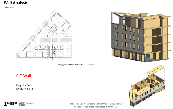
Wall Analysis
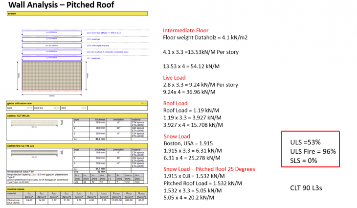
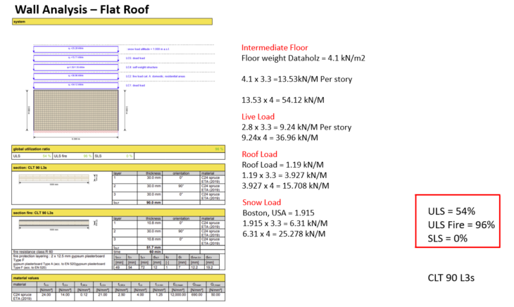
Two wall build up analysis were conducted to test the impact of different roof types. The building in question has a pitched roof construction which was tested to see if it was comparable to a flat roof alternative. The results indicate that there is minimal difference between roof systems impact on the wall below.
Floor Analysis
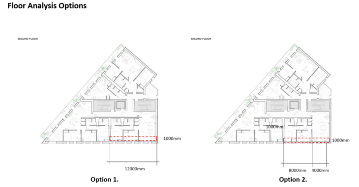
Two floor options were analyzed as options for construction. Option 1 was a continuous floor beam that spanned the 12m gap between structural areas, whereas option 2 broke the continuous span up into 8m and 4m spans with a supporting wall beneath. Three different floor build ups were tested to optimize the floors construction.
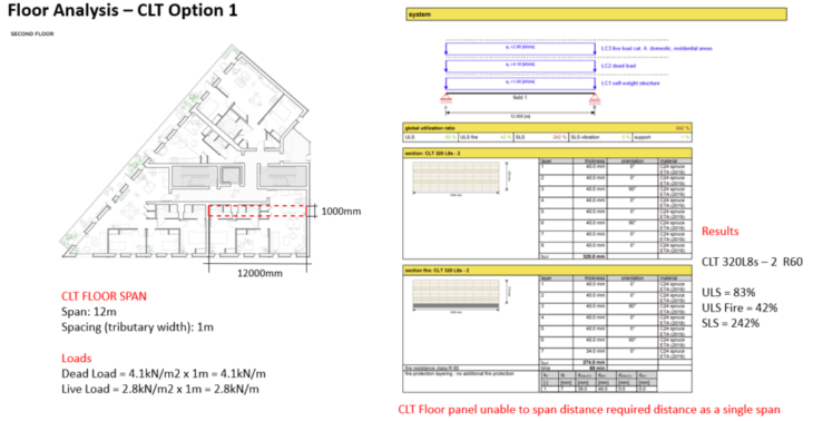
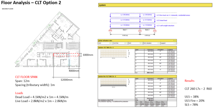
The analysis shows that, if CLT was to be utilized for the floors construction, It would be unable to span the 12m span with the maximum available CLT systems. However, by utilizing floor option 2, the CLT would be able to span the required distance.
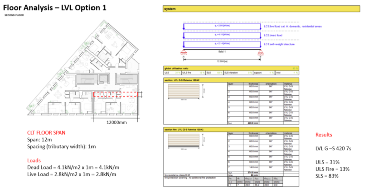
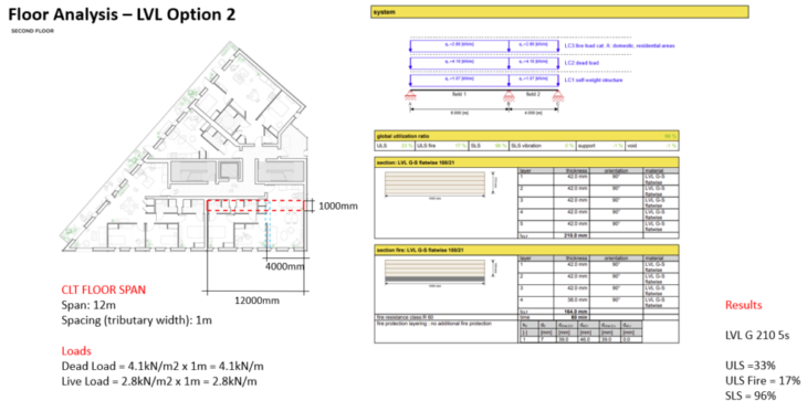
If the project was to utilize a LVL floor system, it would offer the flexibility for both floor design options. LVL, unlike CLT is able to span the 12m distance in a single panel utilizing a LVL G-S 420 7s. By utilizing floor option 2, the LVL thickness could be reduced to a LVL G 210 5s panel.
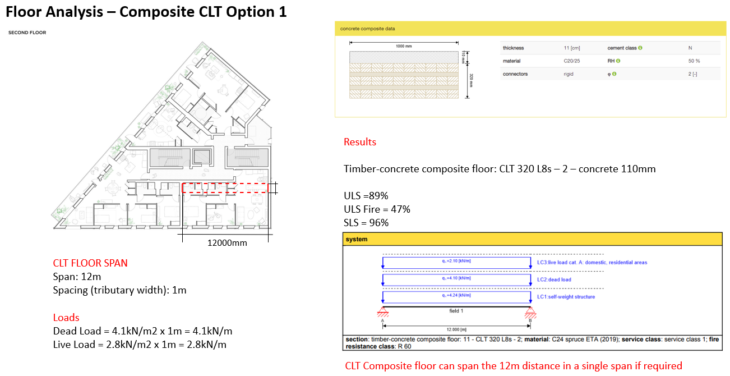
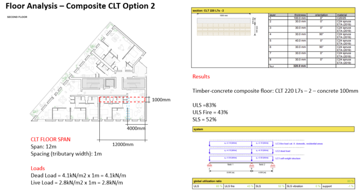
The final flooring system analyzed was a CLT composite deck. Similar to the LVL system, the CLT composite deck was able to span the 12m distance in a single span utilizing a CLT 320 L8s – 2 panel with 110mm concrete topping. Design option 2 allowed the CLT panel to be reduced in thickness to a CLT 20 L7s -2 with 100mm concrete deck.
Results Analysis
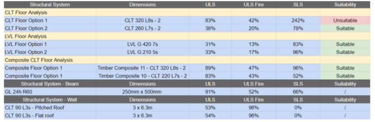
The results show that, while all flooring systems are capable of allowing for both design options, the limitations of the CLT make it less flexible then the other LVL or composite deck options. CLT 90 L3s walls allow for both a pitched roof as used in the original design, or a flat roof alternative. A Glulam 24h with R60 fire protection has the structural capabilities to support the weight of the floors above it.
While the structural analysis of a building is crucial in order for it to function, other issues such as fire and acoustic issues must also be understood and addressed in order to maximize a buildings construction in both its architectural design or for the occupants who will use it.
Useful Links
Generate Architects
https://generatetechnologies.com/
Calulatis
https://calculatis.storaenso.com/
Dataholz
https://www.dataholz.eu/
Structural Analysis of a Multi-story Mass Timber Building is a project of IAAC, Institute for Advanced Architecture of Catalonia developed for MMTD in 2022 by Student Jack Byrne. Faculty: Felipe Riola Parada. Course: Techniques 1.2