Abstract
The system development process started with inspiration from the natural world. Slime mold – a single cellular organism renowned for its ability to find the most optimal route to find the source of food was an initial driver of the design. During the development of the project initial ideas shifted towards a wooden, modular system which could be assembled and disassembled with ease. Timber planks of the same size would allow anyone to use and build the system.
Inspiration
Design initial inspiration came from slime mold.
“Slime molds are among the world’s strangest organisms. Long mistaken for fungi, they are now classed as a type of amoeba. As single-celled organisms, they have neither neurons nor brains. Yet for about a decade, scientists have debated whether slime molds have the capacity to learn about their environments and adjust their behavior accordingly.” – @Katia Moskwitch, quantamagazine
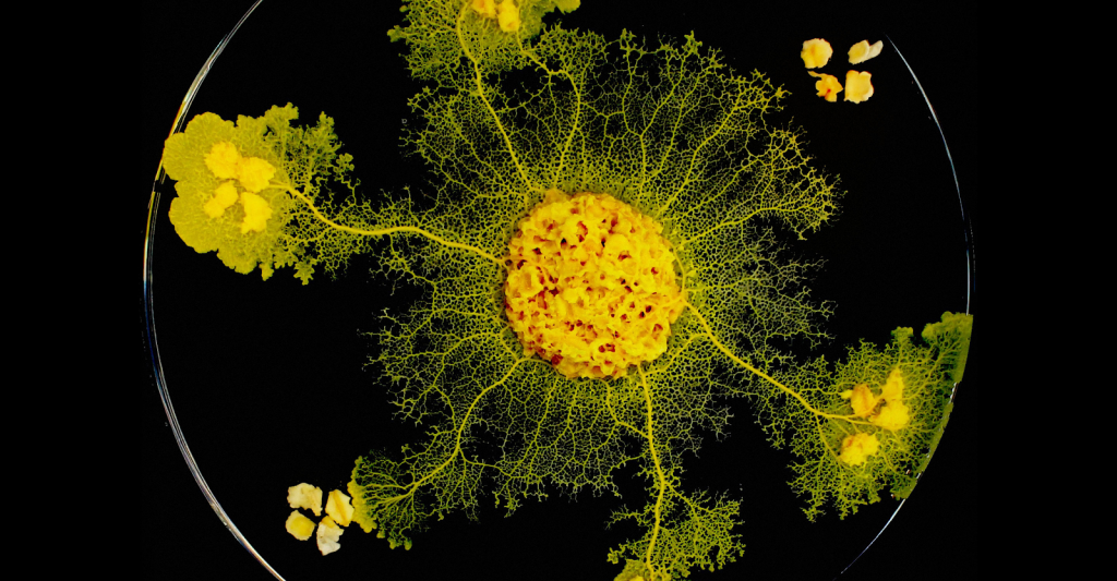
@Audrey Dussutour, CNRS
Initial form finding and exploration
Slime mold behaviour was studied and an attempt was made to simulate its growth using grasshopper.
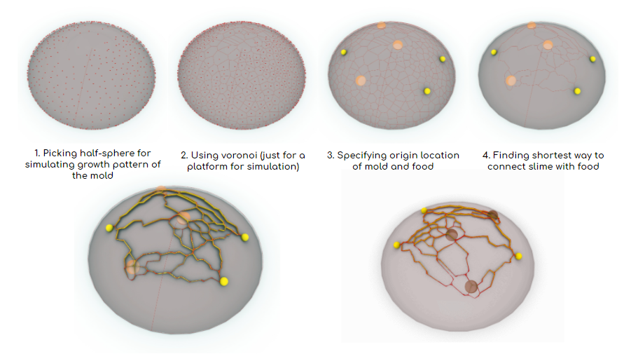
The next step was to take initial algorithm and try to simulate the growth on more complex form.
Final results were then meshed and used in further form development.
Initial exploration of fabrication possibilities using timber
The initial approach towards fabrication methods was to use CNC machine to create tessellated model of the found geometry.
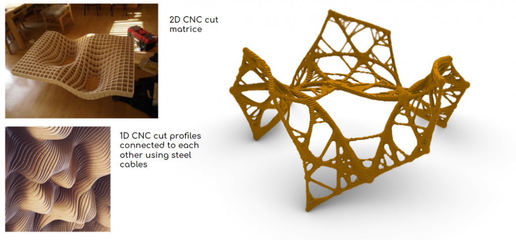
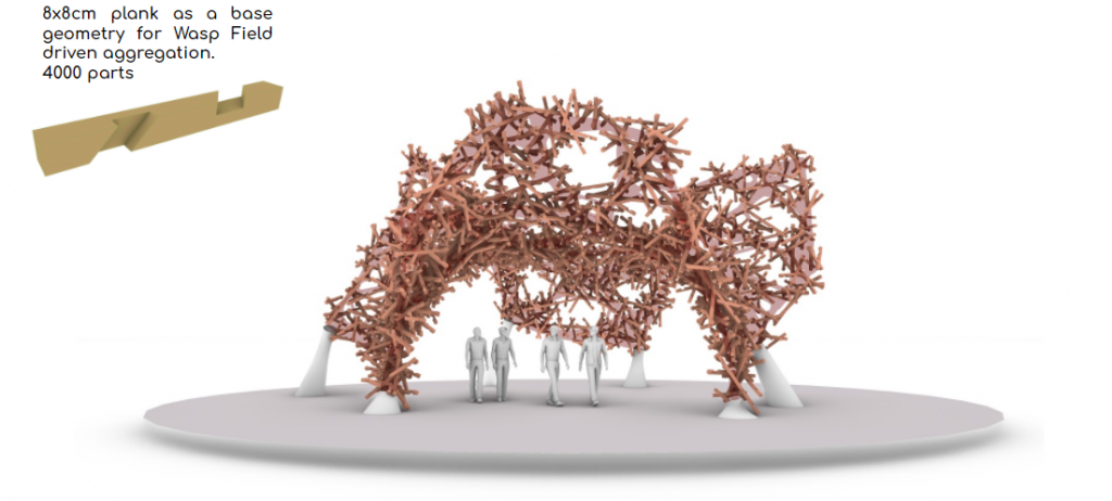
After analyzing the first method it turned out that it was to wasteful during fabrication – another approach had to be introduced. Second idea came up to be usage of reciprocal wood connections, but done in a less organized way. The WASP plugin for Grasshopper was used to aggregate timber elements based on the initial shape and create three dimensional figure..
Outcomes of this experiment were not satisfying either. Therefore, another approach had to be found. Form finding via subdivision of the surface was the next step in project development.
Exploration of form subdivision system and grid creation
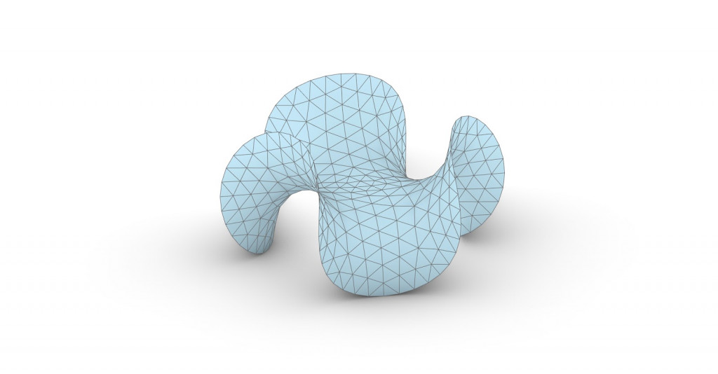
The form found in early stages was used as the boundaries of the surface which was created for further experiments.
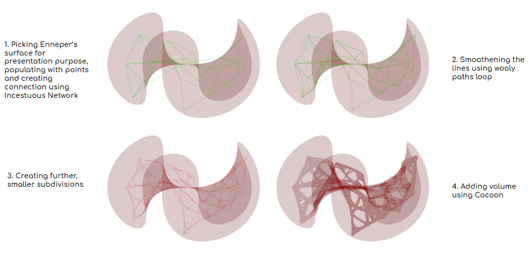
During initial tessellation attempts Enneper’s surface isolines with center point in the middle caused issues with immensely high number of small faces in the middle. In order to prepare model for Karamba analysis, further dividing methods were used.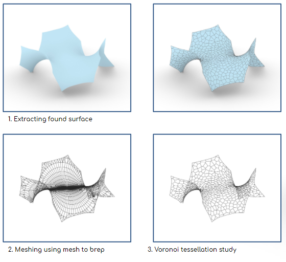
To address specific matrix of Enneper’s surface isocurves and to provide reasonable subdivisions for analytic mesh further study was done.
By extracting isocurves and creating increasing number of subdivisions and connections, a simplified mesh was created.
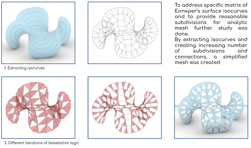
Two outcomes were possible while utilizing the algorithm:
1. Triangular subdivisions
2.Triangular + Quad sbudivisions
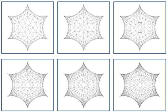
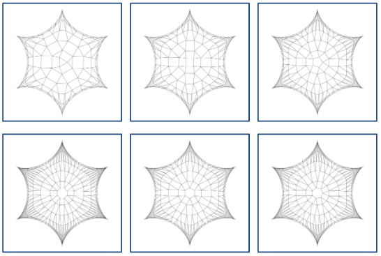
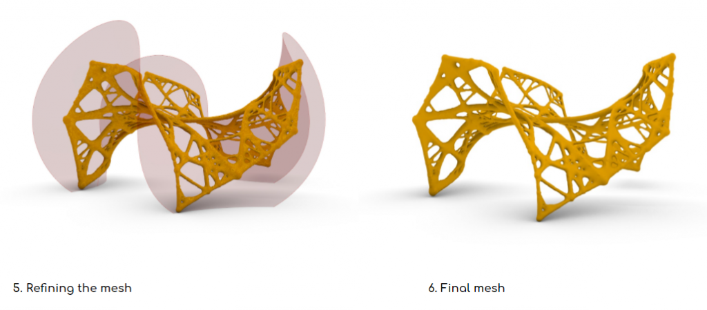
Further steps taken for creating clean mesh for analysis was trying different loop subdivision approaches to unify the geometry.
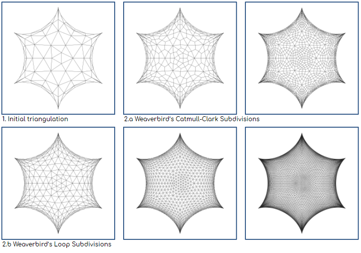

Final iteration was achieved and model for full surface analysis was created.
Structural analysis
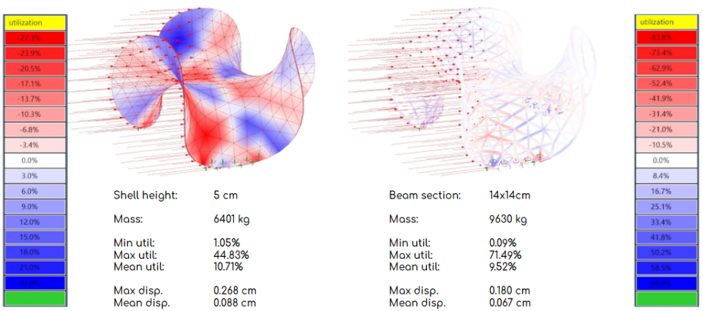
First structural analysis was an exploration of different approaches towards fabrication. The first one was done using shell model, the second using beam. Whole surface was analyzed to better understand how it behaves. Self-weight, gravity and wind were the cases analyzed in simulation.
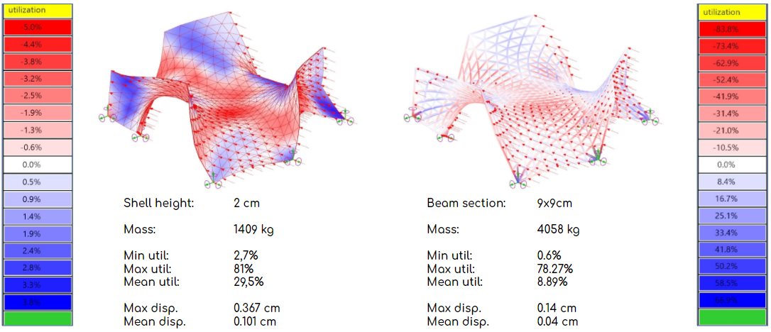
The second step in simulation was to go back to trimmed surface and repeat the analysis.
Further experiments conducted was checking if by increasing the height of the shell, based on the utilization values, the structural stability can be increased. The other objective was to reduce the amount of material used.
![]()
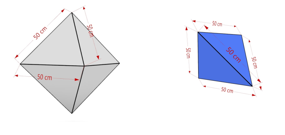
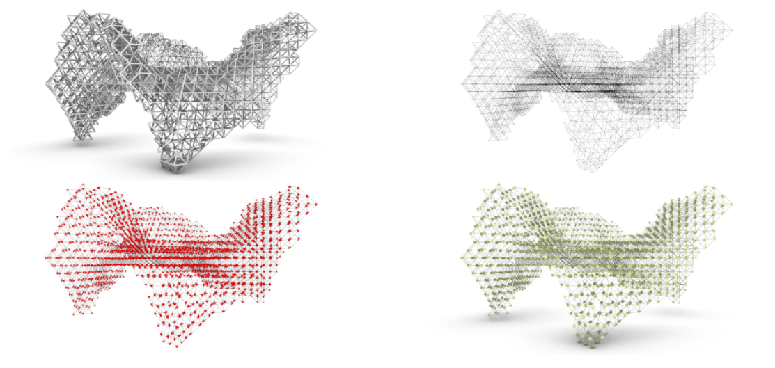
Found geometry was then meshed to create boundaries and set the model for wasp aggregation.
By using octahedrons and tetrahedrons and aggregating them together using WASP plugin, a 3-dimensional grid of the same length was created.

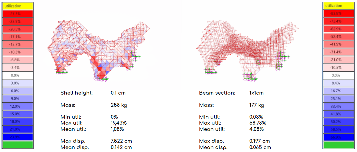
The geometry achieved during grid experiment was taken back for analysis in Karamba to check whether initial objectives were met. The first analysis was done in secluded environment without the wind-load taken into account. Thanks to this it was possible to drastically decrease the section(9×9 cm to 1×1 cm and 4058 kg to 177 kg) in comparison to earlier analysis. That would highly decrease the cost of the system if used in interiors.
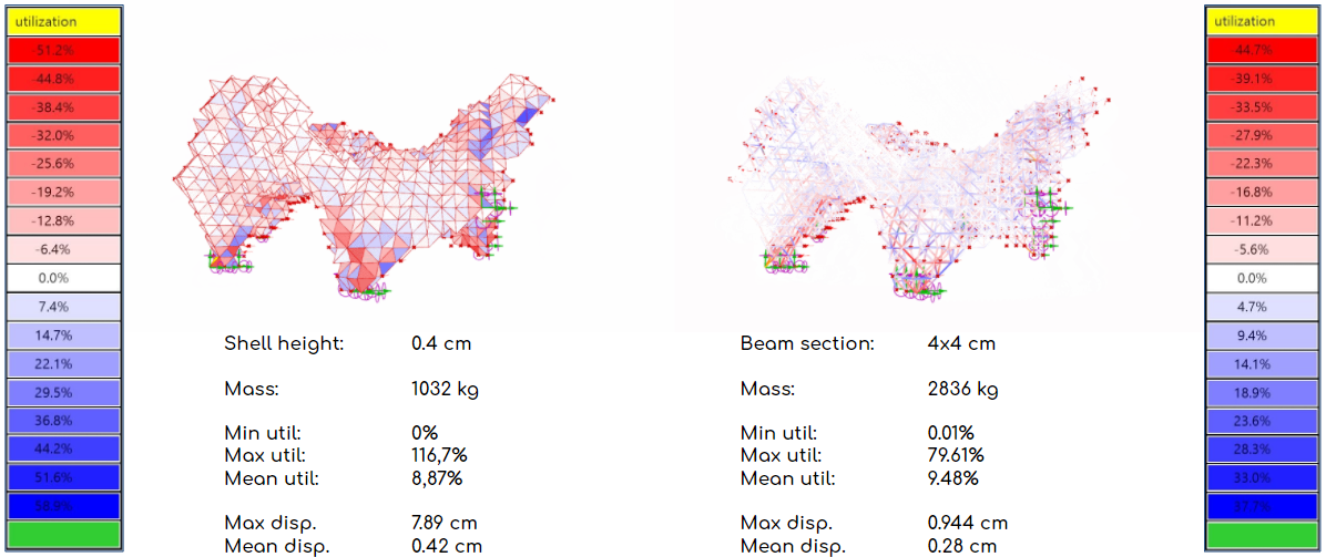
The final analysis was done with the wind-load result case to make sure that the structure can be built outside. This search forced the beam section to be increased to 4×4 cm, but the overall mass was still much lower then while using the original grid system (4058 kg compared to 2836 kg)
Final fabrication approaches
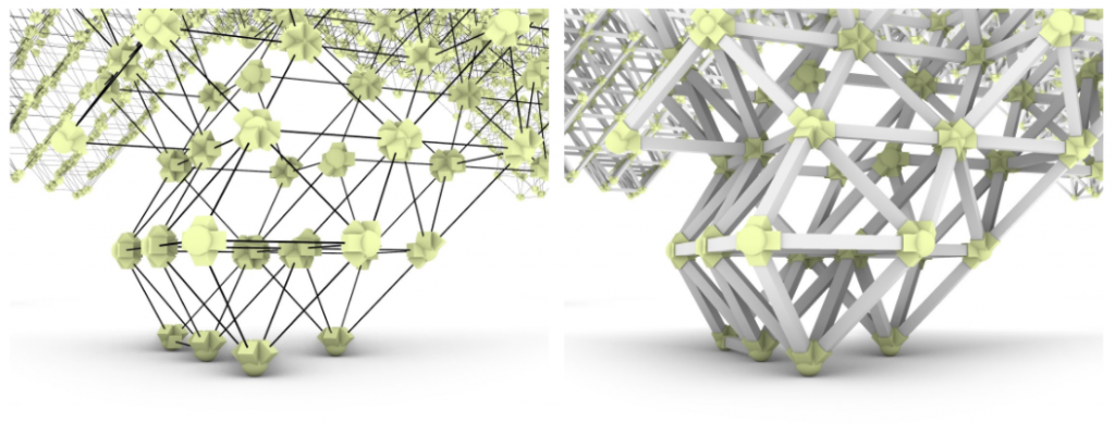
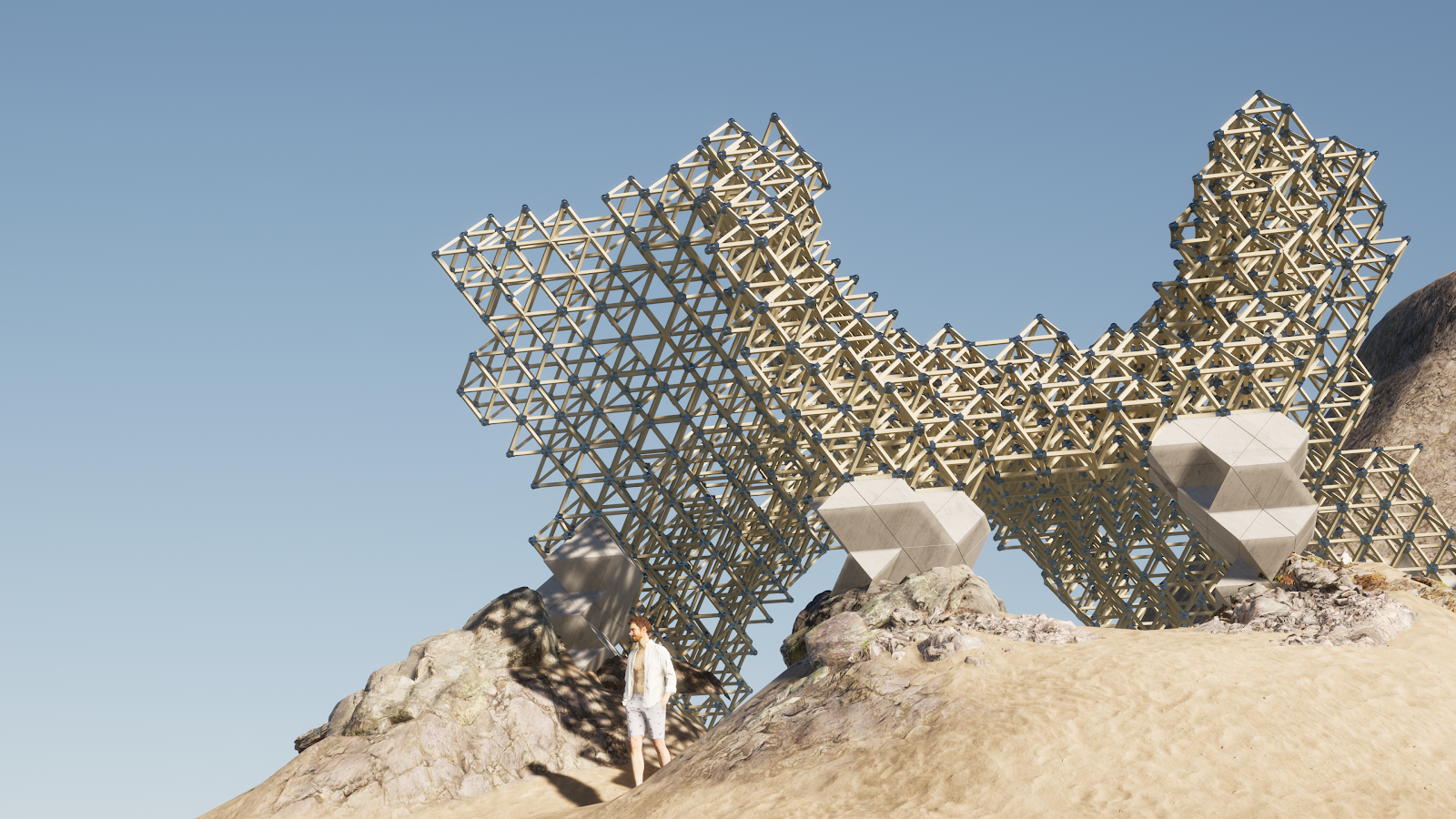
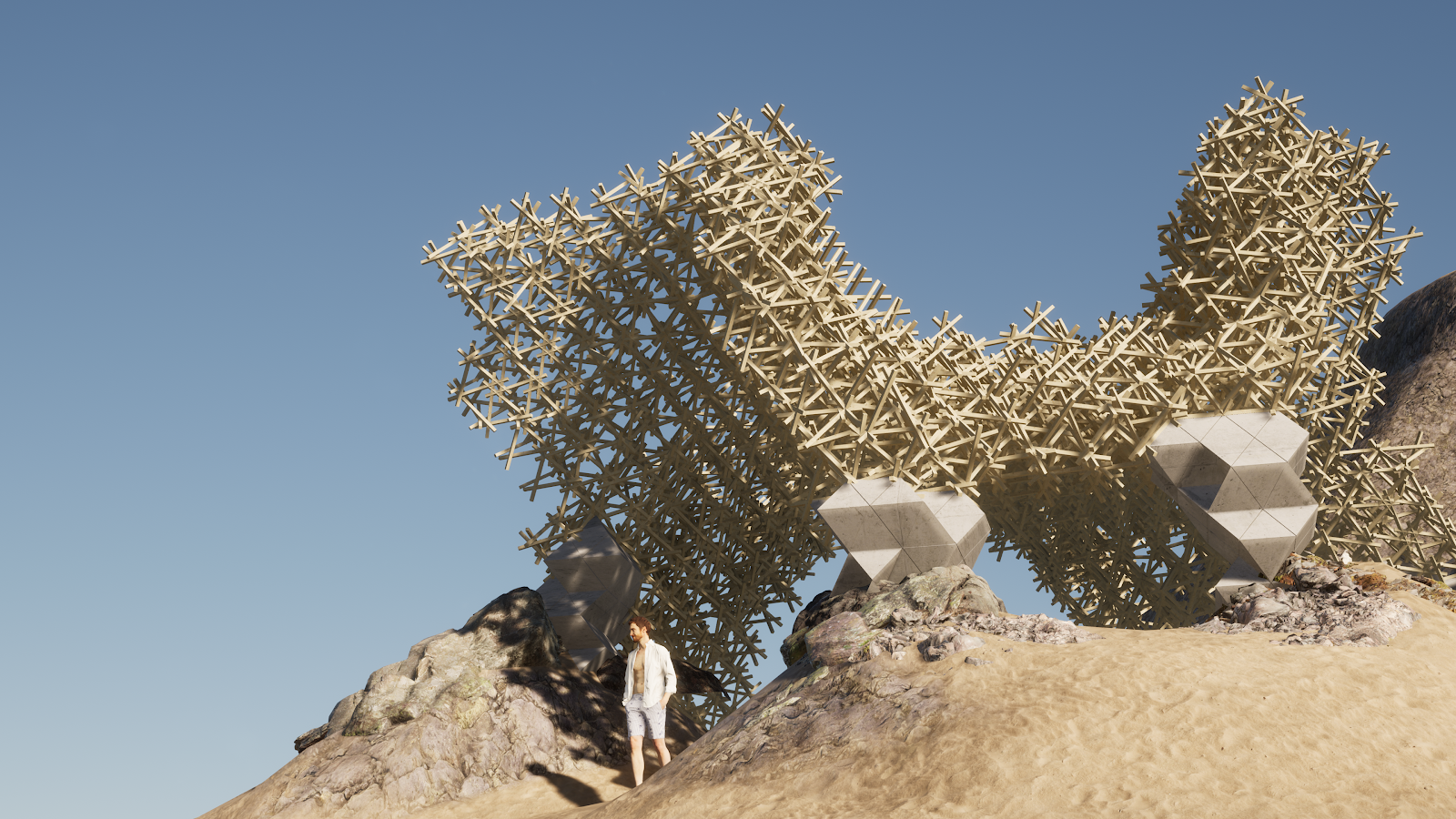
Final ideas for fabrication was to either use steel plates as way to join pieces or to use the self-supported approach. The element used were 5909 4 x 4 cm wooden planks, 50 cm length for regular grid and 70 cm for reciprocal approach.
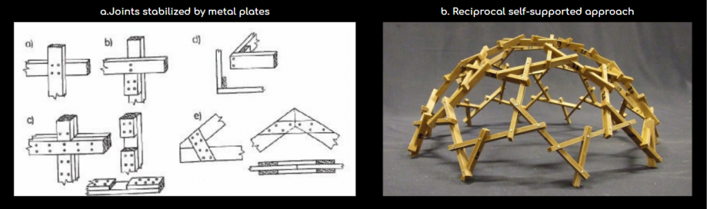
After analyzing the steel plates approach, it was changed to custom plug and play nest-joint system. This action was done to make the fabrication as simple and easy as possible. As the grid consists of the elements of the same length and is based on tetra and octa-hedrons it has a finite number of joint types, which can be prefabricated or 3d-printed.
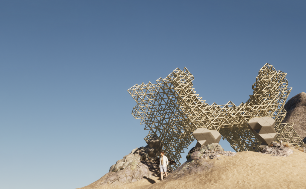
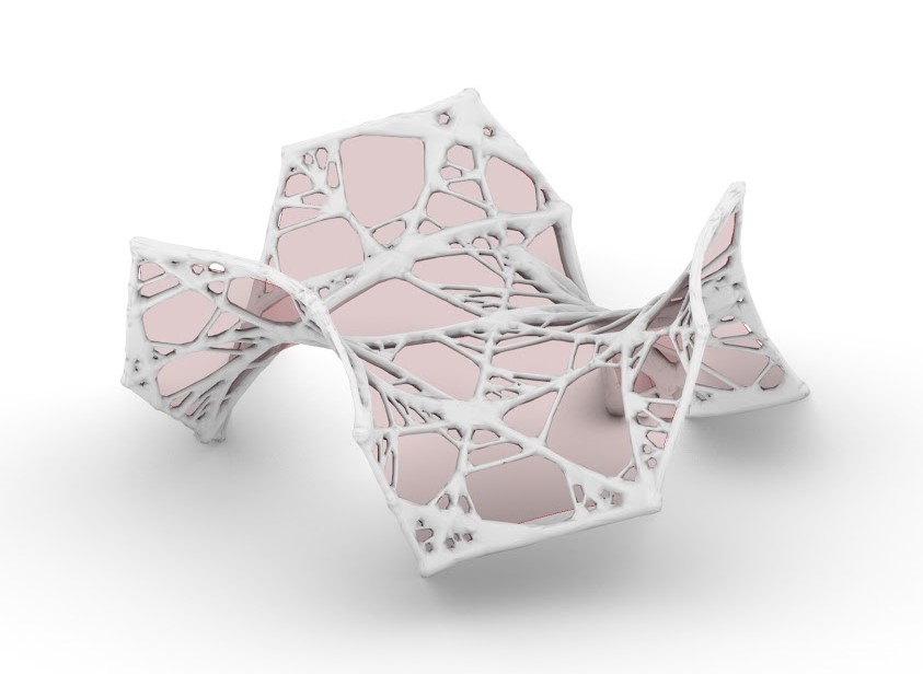
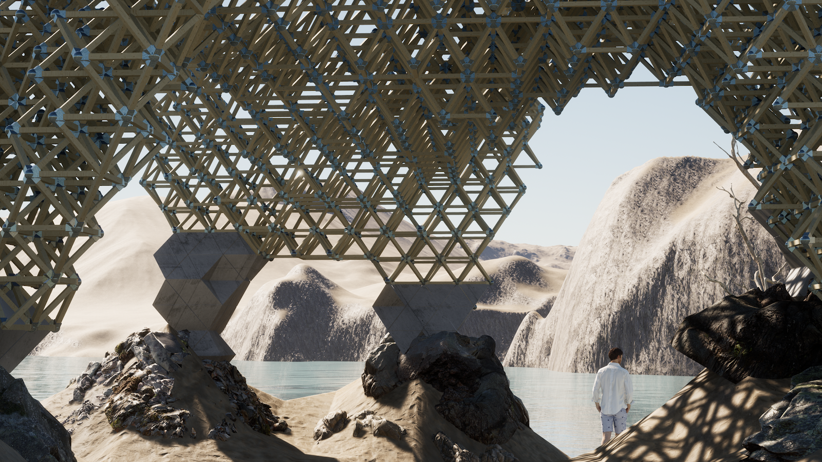
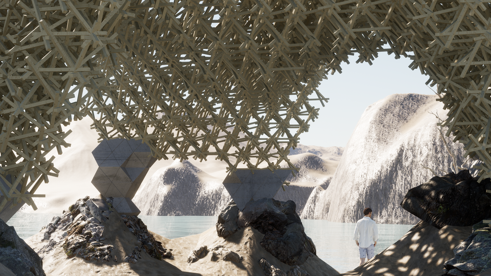
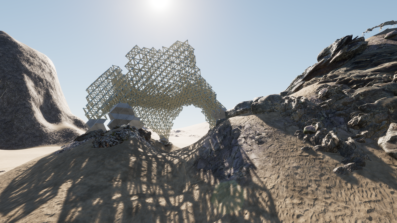
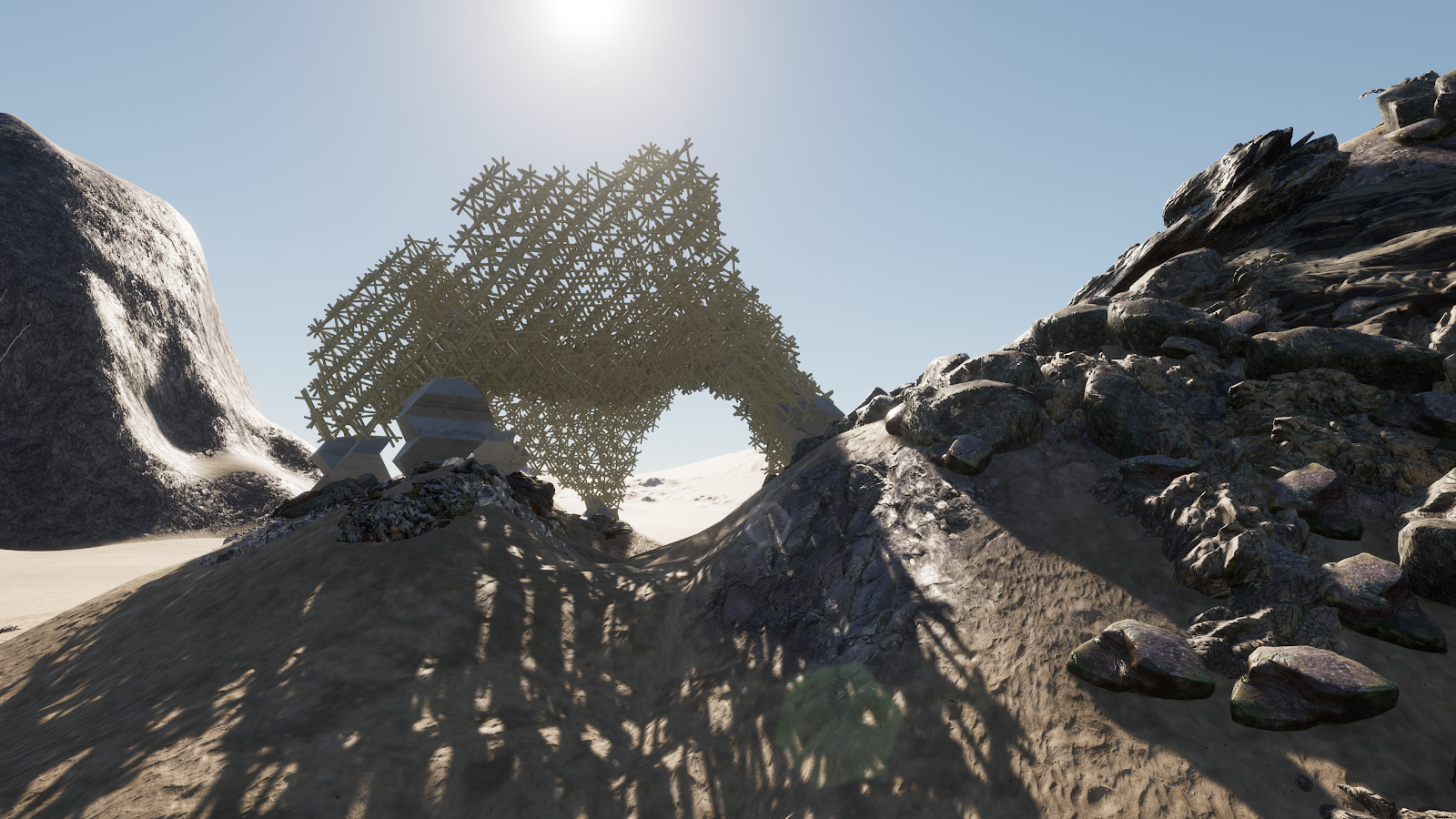
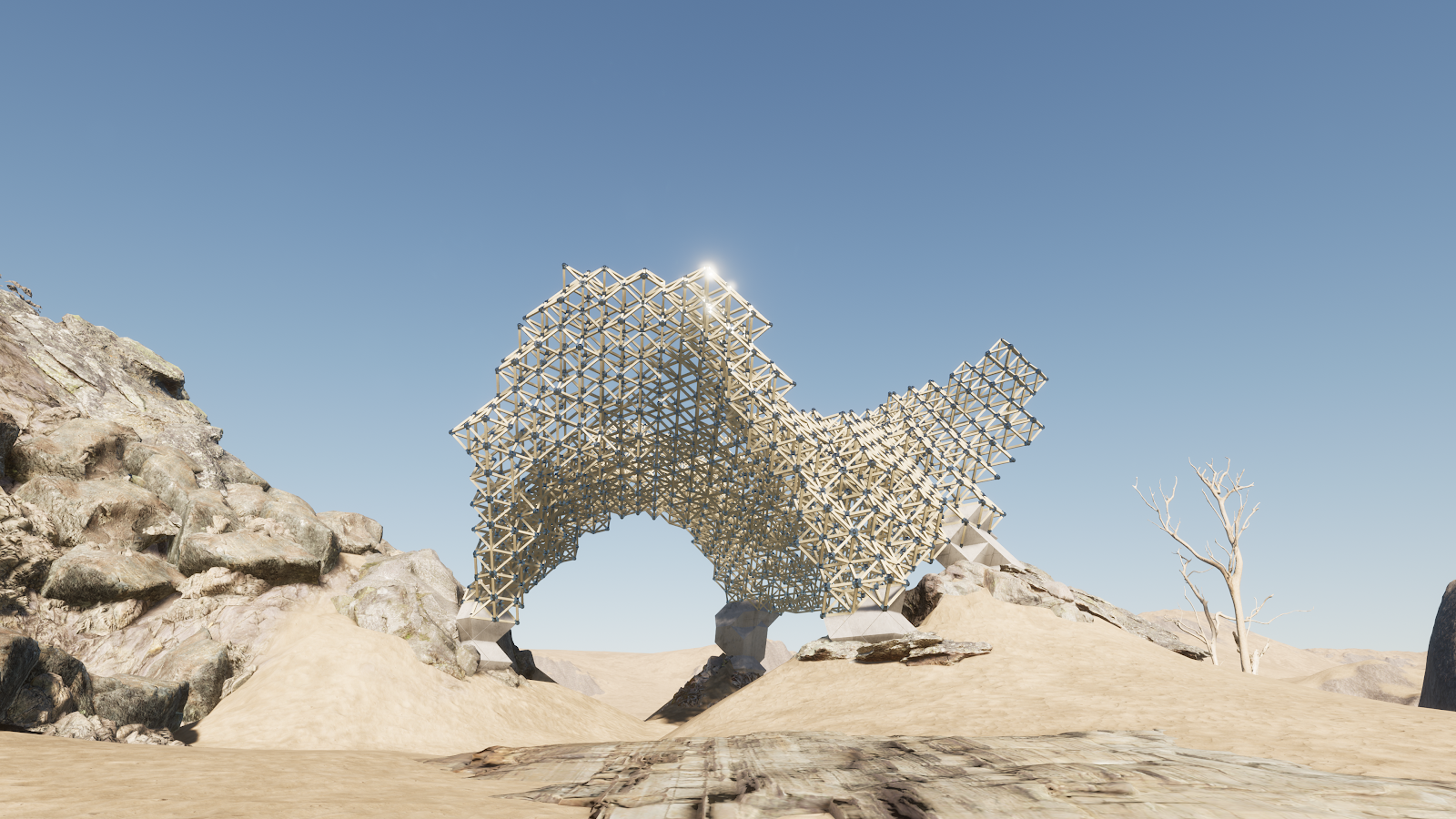
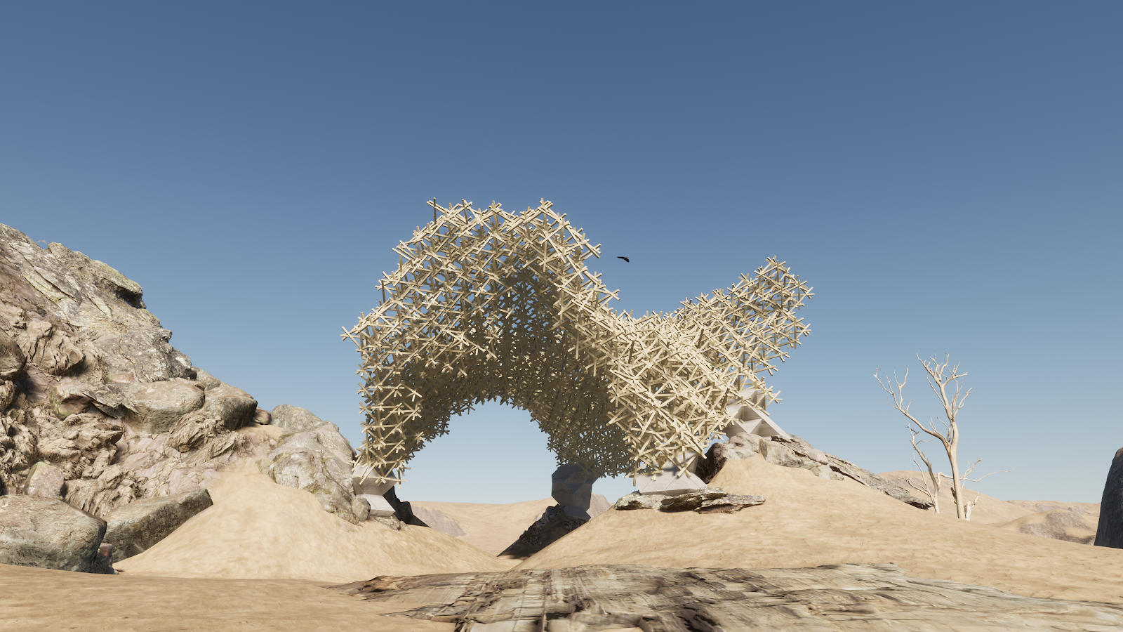
The final outcomes of the system are two fabricatable systems – regular and reciprocal.
Final renders of regular grid system and reciprocal approach
credits
Modular wood pavillion is a project of IAAC, Institute for Advanced Architecture of Catalonia developed at Master in Advanced Computation for Architecture & Design in 2020/21 by Aleksander Mastalski
lead faculty: Arthur Mamou Mani faculty assistant: Krishna Bhat
