MeX_PRIMER
AN EXPLORATION IN MESHING USING LOW-POLY SUBDIVISIONS AS A PRIMER FOR MESH SUBDIVISION AND RELAXATION. THROUGH THIS PROCESS THE USER CAN GENERATE AND CONTROL COMPLEX GEOMETRIES AND PATTERNS STARTING FROM RELATIVELY SIMPLE TRIANGULAR AND QUADRANGULAR MESH FACES. IT SETS A SCRIPTED ENVIRONMENT WITH THE PRIMER AT ITS VERY CORE CHANGING AND CREATING GEOMETRIC PATTERNS.

Mesh Geometries
We start by setting up our script for mesh relaxation and striping, and begin exploring 6 different low-poly mesh options.
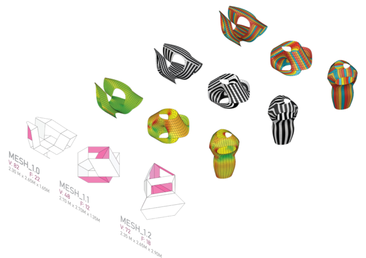
Using Weaverbird’s Catmull-Clark Subdivision, we set up our smoothing and subdivision setting as follows
CATMULL-CLARK SUBDIVISION CONFIGURATION:
LEVEL: 2
SMOOTH NAKED EDGES: CORNER FIXED
ANCHOR POINTS: NAKED EDGES
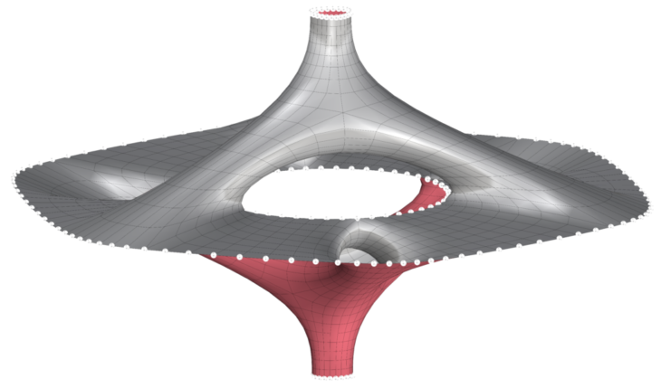
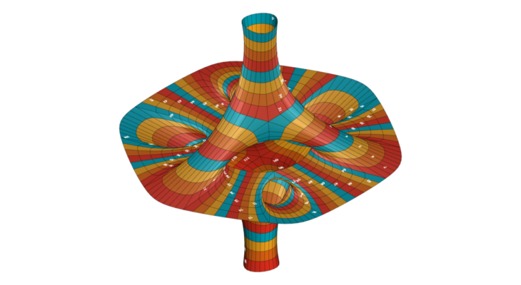
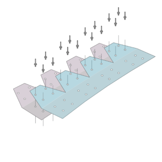
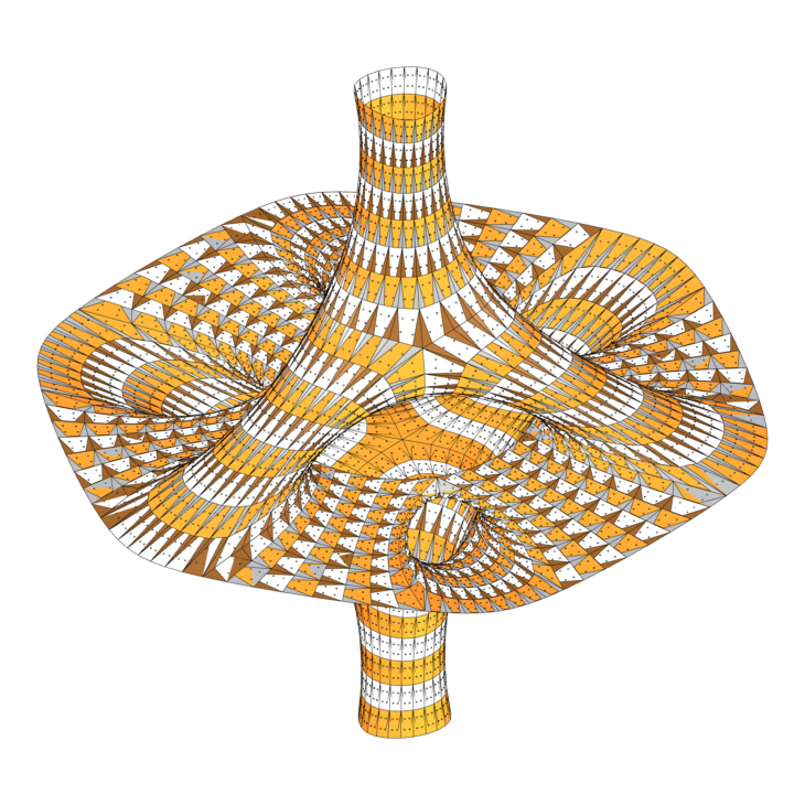
Mesh Relaxation
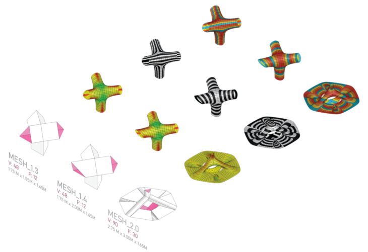
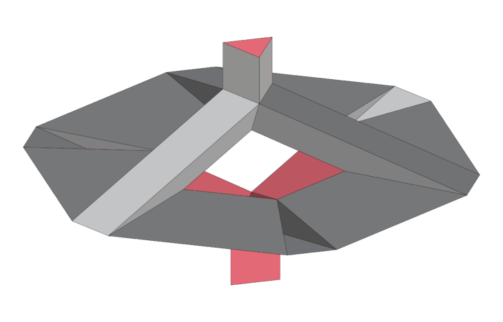
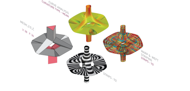
At this point, we choose Mesh 2.0 to go forward with based on the following criteria:
- Curvature factor at all points of the surface are relatively low, meaning easier manufacturability
- The intersecting geometries and tube shaped faces offer many possibilities for repeatable pattern generation
- Hexagonal plan section allows for interesting repetition for multiple units in all directions
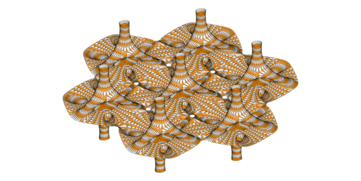
Mesh Topologies
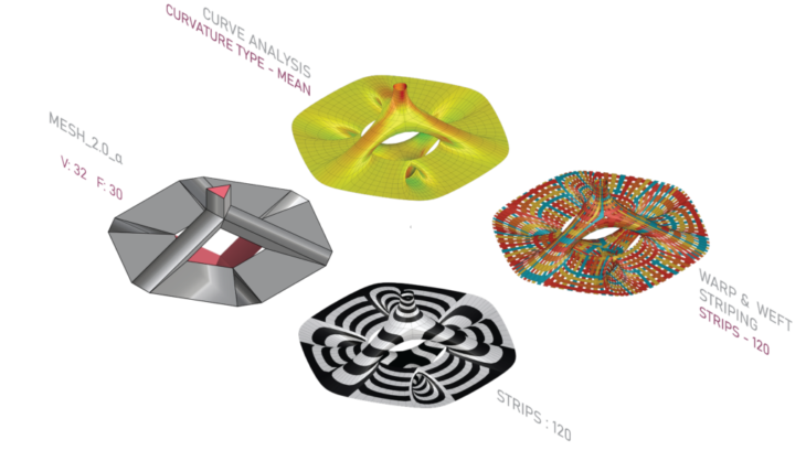
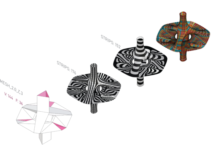
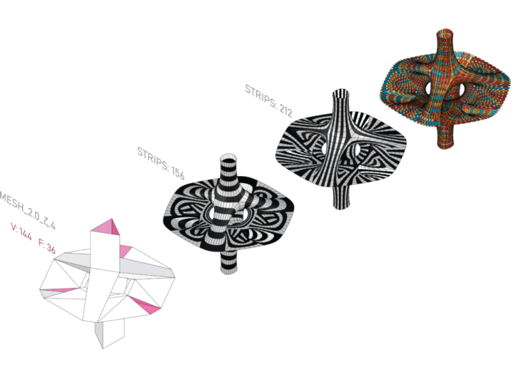
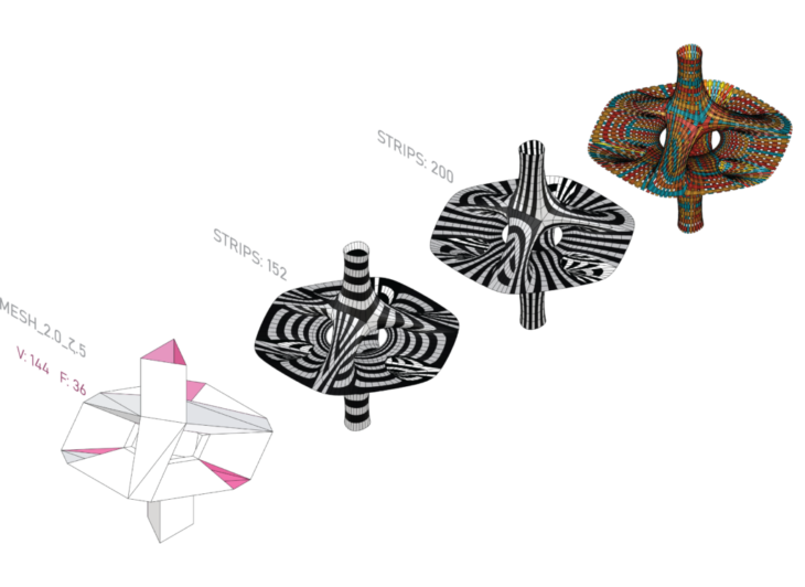
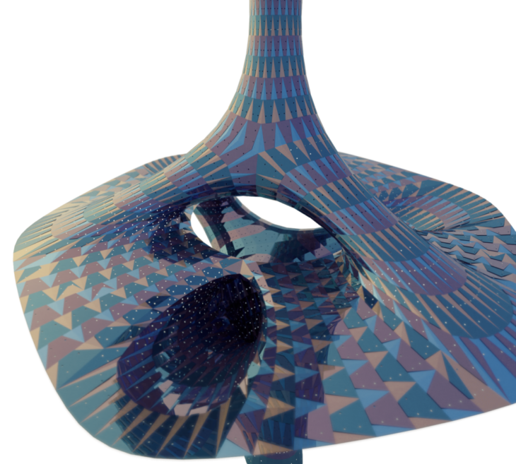
The low-poly mesh definition allows for easy manipulation of the faces. By rotating and subdividing different mesh faces we are able to control the final stripe pattern and topology.
Mesh 1a
Mesh 2b
Mesh 2c
Mesh 2d
Mesh 2e
Mesh 2f
- Controlling the initial topology by having only quad mesh faces allow for easy manipulation and organization of the strips
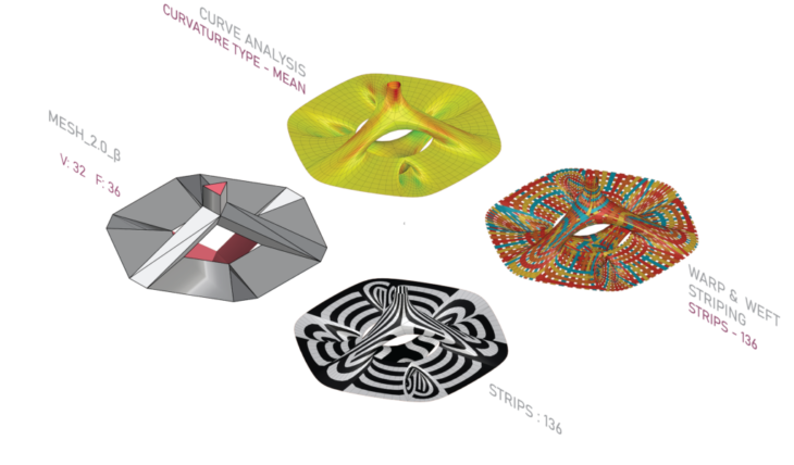
- Beginning to divide our mesh into triangles on the tube shaped faces, we start to get interesting patterns going along those directions. Strip number increases because triangulation breaks continuity.
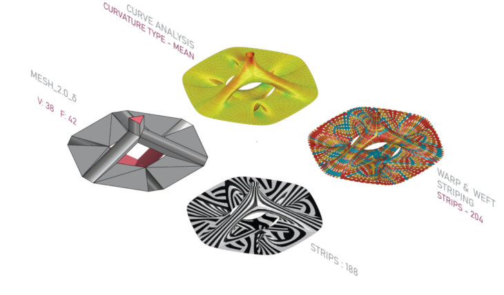
- Increasing the number of subdivisions and triangular faces, we start having very interesting patterns. Continuity greatly decreases and the number of stripes almost doubles. We also start having a contrast between wide stripes where we have less initial subdivisions and thinner stripes in areas with higher subdivisions
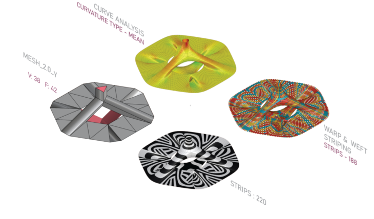
- Dividing the larger faces, we can maintain continuity on the tube shaped faces, but start to have discontinuous patterns on the flat faces. Strip number increases as more discontinuity is occurring.
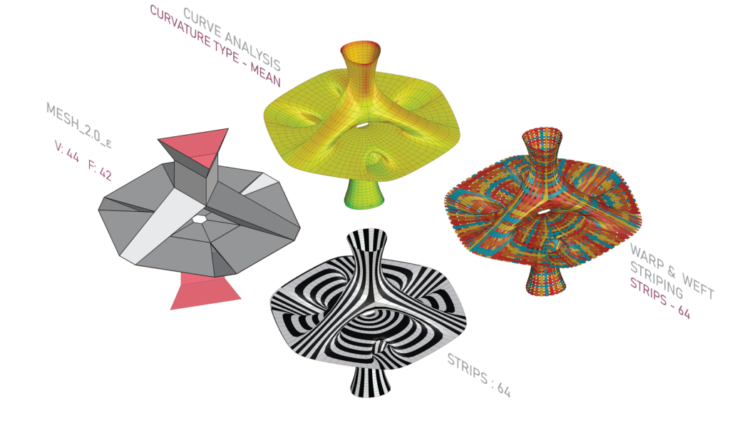
- Adding offsets to the internal edges as well as the top and bottom faces, we can increase the surface area and get more repetition. Despite having a larger surface area, orienting the faces to be more linear, we get very high continuity and the number of strips drops dramatically to 64, but strip length also increases.
- With wider tubular faces, and a bigger top and bottom, we can achieve a more desirable stable structure. Retaining only quad faces, we are able to organize the strips with ease for fabrication.
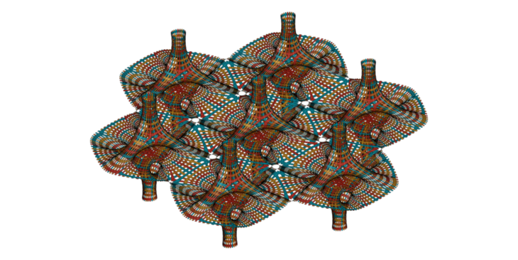
Mesh Face Topologies
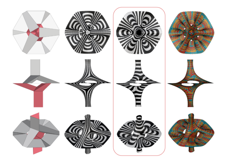
After subdividing, we further explore different striping patterns by rotating each face and analyzing the results.
Mesh 3a
Mesh 3b
Mesh 3c
Mesh 3d
Mesh 3e

Mesh 3f
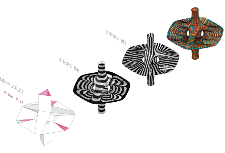
- Maintaining all quad faces, we obtain a relatively high number of strips when strips are all oriented in the same direction, due to the discontinuities created because of the irregularity of the geometry
- Orienting the top faces to achieve circular looped faces, while the bottom with vertical stripes, we can achieve a 90 degree rotation between the top and bottom strips, creating an interesting aesthetic contrast, but maintains similar strip quantities.
- Dividing some quad faces into triangular ones with a script, we break the continuity on those faces but generate more intricate patterns. This creates some issue for manufacturing as we lose edge anchor points for some strips. Low continuity here means a higher number of strips.
- Keeping the same subdivisions, but rotating the faces, we can achieve similar results but with a higher number of strips.
- Dividing the tubular faces, we achieve a lot of discontinuity on the curved surfaces., which would not be desirable in manufacturing.
- Rotating the faces, we have a cleaner pattern with higher continuity.
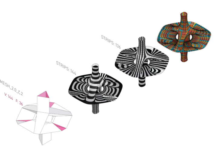
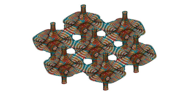
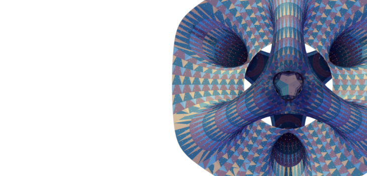
Final Mesh Iteration
The Final Iteration chosen is the Mesh 3f and the warp & weft direction for the same was also finalized because of the kind of continuity in strips it forms which in turn reduces the amount of strips formed for fabrication.
Mesh 3f Details:
- Total Strips: 112
- Open: 48
- Closed: 64
Final Mesh Iteration
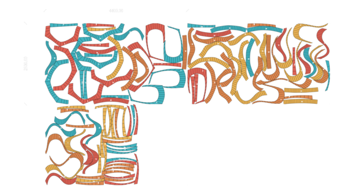
Unrolling & Nesting
We unroll the strips and lay them flat to analyze them for Laser Cutting
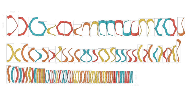
Using the OpenNest plugin, we nest the strips onto three 4400 x 2500 mm sheets which is the bed size of a GWEIKE LF3015LN – Fiber Laser cutting machine which we used as a reference
3 Sheets Needed
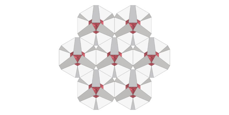
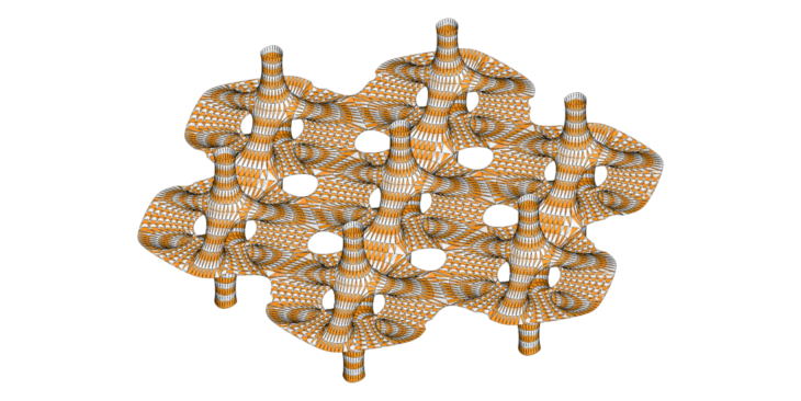
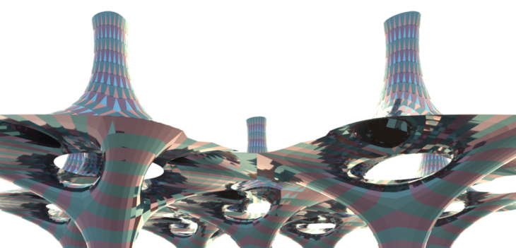
Further Development
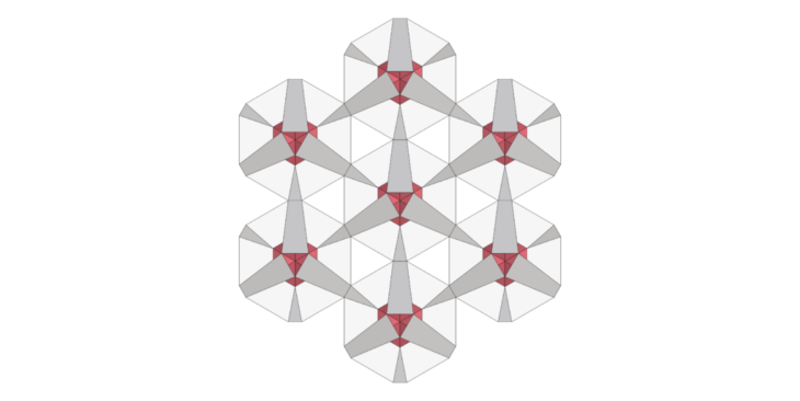
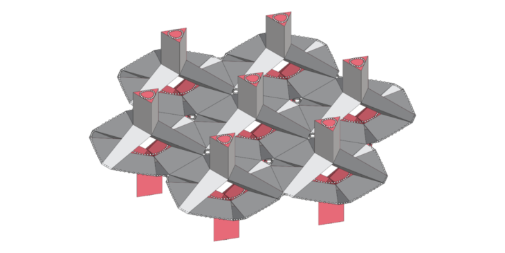
We further delved into the idea of tessellating this mesh to create a Pavilion.
There’s two options in this as well where the module (Mesh 3f) is being connected to each other either using :
- the longer naked edges as shown in the figure FD1.0
- the shorter naked edge as shown in figure FD2.0
FD1.0
FD2.0
FD1.0 Kangaroo Anchor Points
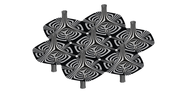
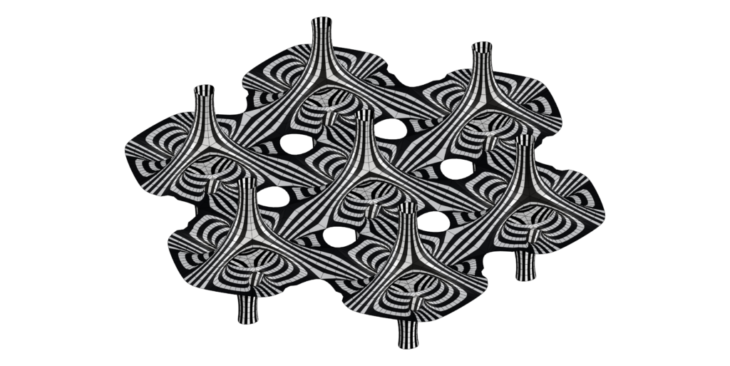

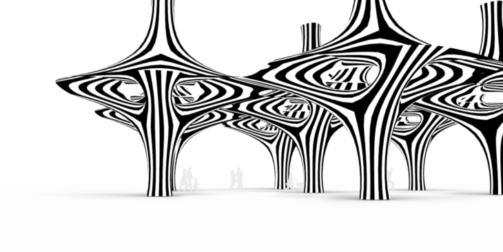
Dragon Skin
DragonSkin, a fabrication design strategy developed by overlapping subsequent strips with trapezoidal flaps and riveting them. This method can facilitate fabrication and creates a striped scale-like aesthetic for the Final Mesh Iteration that was selected
DragonSkin Joinery

Renders
MeX_Primer // SOFTWARE I is a project of IAAC, Institute for Advanced Architecture of Catalonia developed at Master in Robotics and Advanced Construction seminar in 2021/2022 by:
Students: Alfred Bowles, Mit Patel, Huanyu Li
Faculty: Andera Graziano
Faculty Assistant: Eugenio Bettucchi