LA BORDA – Envelope Team
The first thing to identify regarding the envelope analysis to Revit is the component categories:
Envelope Components
- North & South Elevations
- Parametric Blinds
- East & West Gable Wall Elevations
- Steel Structure
- Roof Trusses
- Atrium Gutter
- Parametric Curtain Wall Panel
- Steel Walkway
- Flat Roof Steel Beams
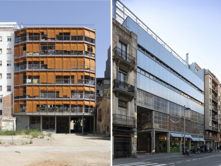
SOUTH & NORTH FACADES (@La Borda)
Secondly, we have to share the workflow between Alexandros and Jack, who are responsible for the modeling of the envelope in Revit BIM Collaborate Pro as well as synchronize the workflow with the central model and the other groups and teams in order to complete a final BIM model of the La Borda Mass Timber Co-Housing in Barcelona.
So the workflow strategy is shared as follows:
- Identify areas required to fulfill the envelopes team requirements.
- Divide the work amongst the team members – Alexandros – North & South Elevations, Jack Atrium roof.
- South Elevation, Galvanized steel supports, Mesh net railing, Timber curtain rollers, Aluminum shutter doors.
- North Elevation – Vertical corrugated Metal Facade, galvanized steel, vertical corrugated metal shade ports, aluminum doors.
- Jack – Semi circular glazed atrium roof, east & West gable wall curtain walls, Steel structure, Roof trusses, Atrium gutter, Parametric curtain wall panel, Steel walkway, Flat roof structure.
- Model the components into the Central Model – designating the correct workset for each component.
- Create new families for certain components – Timber curtain rollers, Roof trusses, Parametric Curtain wall Panel
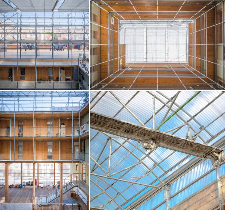
ATRIUM ROOF DETAILS (@La Borda)
During the first step of the analysis, we tried to specify the geometry workflow, identify missing information, and organize the views, layers, worksets, and families categorization between different teams.
The main issues discovered throughout the process are the following:
- Steel Atrium trusses – connections
- Parametric curtain wall panel
- Semi circular roof appearance
- Facades Components issues:
-
- highlighting why certain workflow decisions were made,
- distributing the work – each individual was responsible for a specific part of the building
- how tasks were divided and allocated,
- different parts of the building were allocated to individuals
- envelope South + North Facades
- how modeling conflicts were mitigated,
- CLT wall conflict with the Structural team with align and reference plans so as to lock the insulation with CLT structural and façade envelope.
- Interior wall coordination
- which model elements proved complex or difficult to realize and why,
- Timber curtain Rollers -South Façade
- Corrugation – North Facade
- how the building systems function
- the movable timber roller systems according to the sun pathway
- semi-transparent façade with polycarbonic envelope
- metal opaque vertical corrugated metal
- what assumptions were made based on limits in the as-built information,
- missing information regarding the curtain wall ground floor façade- North elevation
- drawings and real photos did not match – corrugated polycarbonate fixed to galvanized steel had 2 horizontal beams – actual has 3 + 3 on 2nd floor actual has 4
- no dimensions on South façade stairs/ entrance + no window dimensions and levels (ground Floor)
- where coordination between subteams proved critical, and generally
- some elements and levels were locked and could not be altered
- the communication with the interior, structural subteams for the North façade
- South elevation door has been changed with window from other teams – locked
- North façade introduced a door instead of a window from other teams – locked
- any challenges and discoveries encountered along the way.
- CLT wall separated from insulation + envelope facade
- Timber curtain rollers
- Corrugation façade not compatible with BIM LOD 200 for better visual aesthetics of the façade
- curtain wall -> Metal mesh railing as material – > edit pick – graphics -> pattern diagonal
- highlighting why certain workflow decisions were made,
-
SOUTH ELEVATION (@Alexandros Kitriniaris)
NORTH ELEVATION (@Alexandros Kitriniaris)
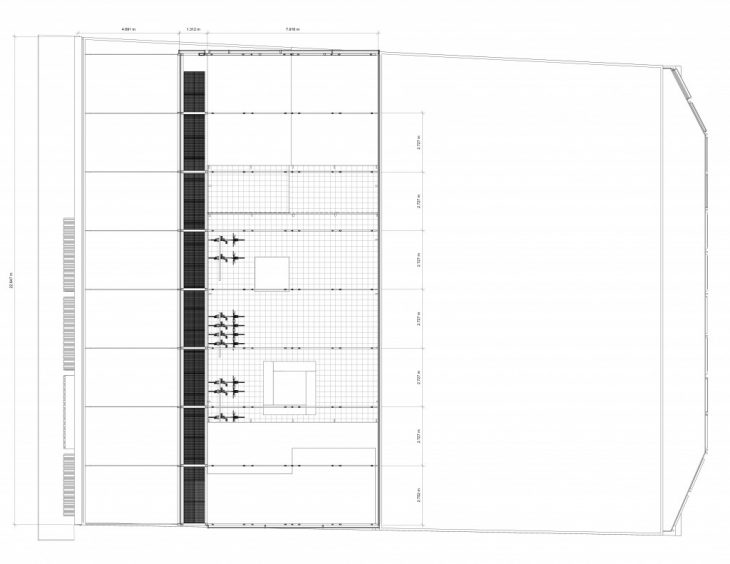
ROOF PLAN VIEW (@Jack Byrne)
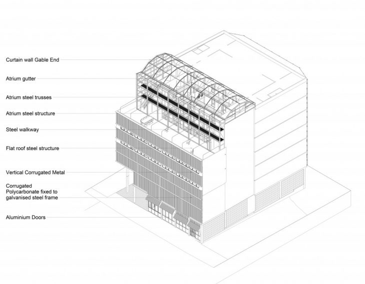
3D AXONOMETRIC OF SOUTH FACADE (@Alexandros Kitriniaris &Jack Byrne)
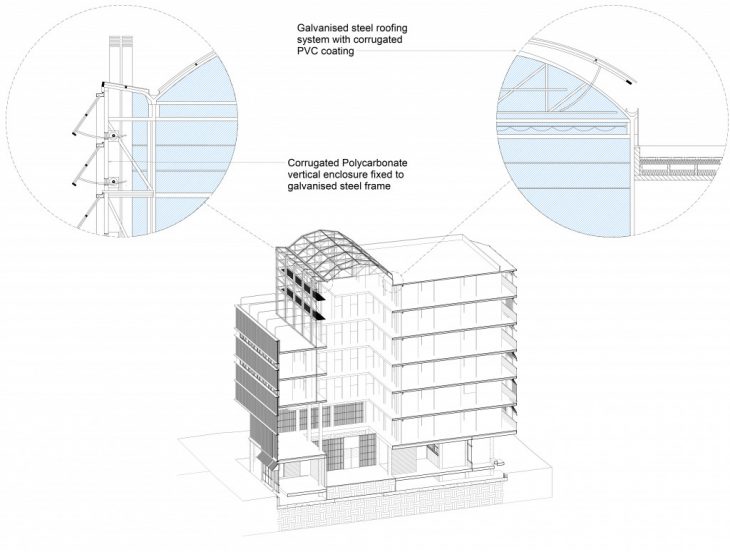
3D SECTION & ROOF DETAILS (@Jack Byrne)
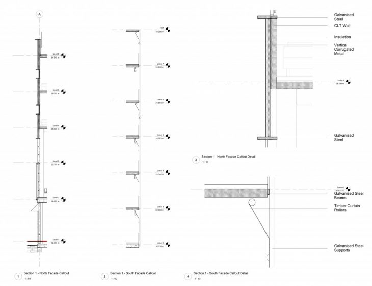
SECTIONS & DETAILS OF THE SOUTH AND NORTH FACADE SYSTEMS (@Alexandros Kitriniaris)
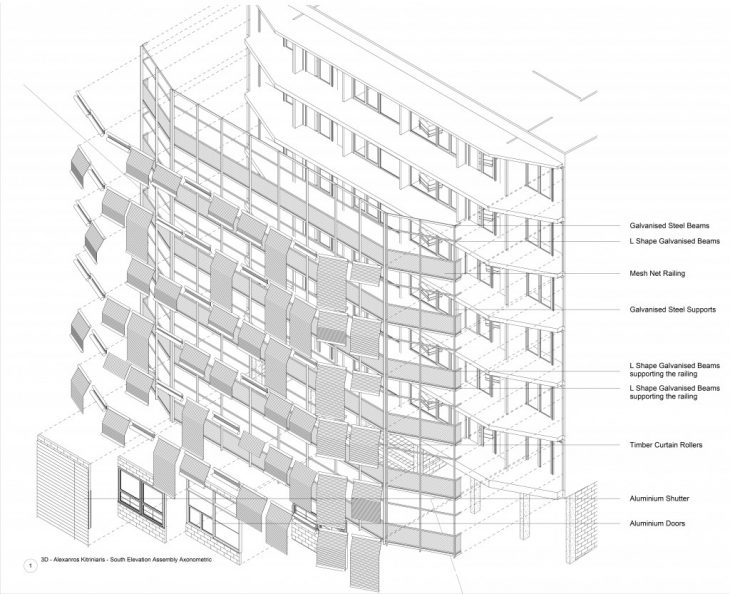
3D EXPLODED ANALYSIS OF SOUTH FACADE (@Alexandros Kitriniaris)
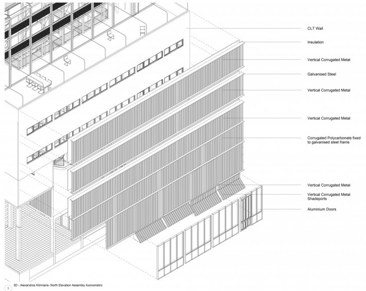
3D EXPLODED ANALYSIS OF NORTH FACADE (@Alexandros Kitriniaris)
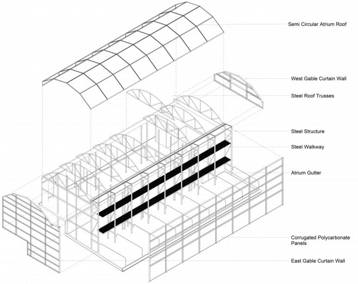
3D EXPLODED ANALYSIS OF ROOF CONSTRUCTION (@Jack Byrne)
—
Mass Timber & BIM Modeling of the La Borda Co-Housing is a project of IaaC, Institute for Advanced Architecture of Catalonia developed at Master in Mass Timber Design in 2021/2022 by Students: Alexandros Kitriniaris, Jack Byrne. Faculty: Michael Salka. Course: Tools 2