LATTICE 03 – Robotic 3D Printed Spatial Lattices
Introduction
LATTICE 03 explores the convergence of digital modeling and fabrication by designing spatial lattice structures and testing robotic rapid prototyping techniques. The goal of the workshop is to design and develop a 3D printed structure made of a collection of discrete spatial lattice cells which together make a complete structure with a focus on gaining an understanding how to develop and implement design fabrication strategies
The challenge for the project is to design and fabricate a lightweight beam structure capable of spanning 50cm., to 3d print it in PLA plastic using a custom high volume, 6 axis 3d printer, and to test the structure for weight to load capacity. Initial design is based on a reference geometry, or structure and using a combination of form-finding software using physics simulation and discretization algorithms to set up toolpaths for prototyping. The key elements of the design are:
- distinct spatial lattice cell shapes exist
- a minimum requirement that the overall cell shape can tesselate to fill space
- distinct routing is possible within the cell,
- cubic cell geometry,
- optimized routing within the cell.
This strategy allows us to build truss-like members in 3D space without the need for printing supports. Using a technique of depositing material continuously in the direction of the stress lines, we are able to print these structures with less material and time than a more conventional “slicing” approach to 3d printing which deposits material in successive horizontal layer. Depositing the material in this fashion also creates more continuity in the direction of the forces within the structure.
Considerations
Because of the routing of movements within the cell, which includes a mixture of horizontal, vertical and diagonal movements in succession, this type of lattice cannot easily be achieved by normal 3D printing techniques, which are heavily dependent on ‘slicing’ and then working in layers either top down or bottom up. Even using a robot’s 6 degrees of freedom, it remains a challenge to orient the extruder at all times so as to extrude where required while avoiding already deposited material.
The approach to resolving design to fabrication challenges involved testing, early prototyping in concert with design development. By recording initial attempts to build the component structures and adding successive layers of complexity by attempting to print combinations with adjacent components, the digital model is adjusted to take into account materiality and the limitations of of the fabrication process.
Geometry Definition
The reference geometry is an arched truss adapted to based on 3 x 3 box truss lattice with diagonal bracing, a flat top surface and an approximated catenary curve for the bottom surface. Depth and width of truss are also approximated based on overall depth using a general equation for a single span beam, WL2/8. These approximation are a factor of the constraints of the workshop format in order to focus design fabrication strategy as opposed to predictable structural performance.
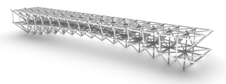
Final Design – Isometric
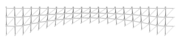
Elevation

Plan View
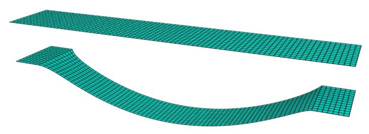
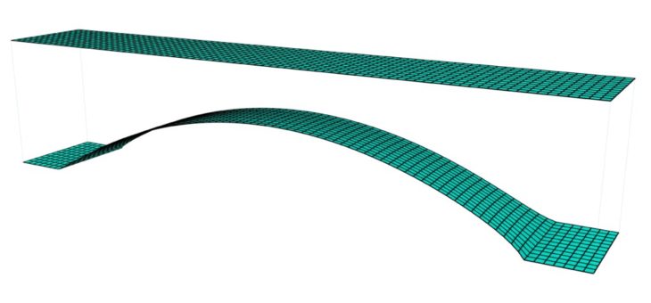
Form Finding
The 5ocm span is defined as a horizontal mesh plane and subdivided into smaller units. Using the kangaroo solver the mesh is deformed, or “relaxed” by applying gravity in order to approximate a catenary arch. The arch is then inverted and connected to the original horizontal mesh to support the horizontal span.
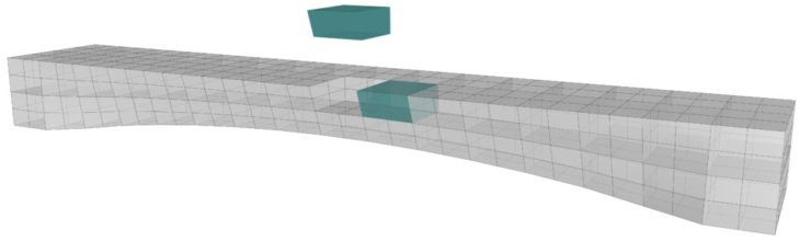
Discretization
The space between these top and bottom faces is connected to create a closed volume. The volume is then discretized subdividing it into individual 3D box geometry using the Pufferfish plugin within Rhinoceros to create individual cells for printing where each cell will correspond to a spatial lattice cell.
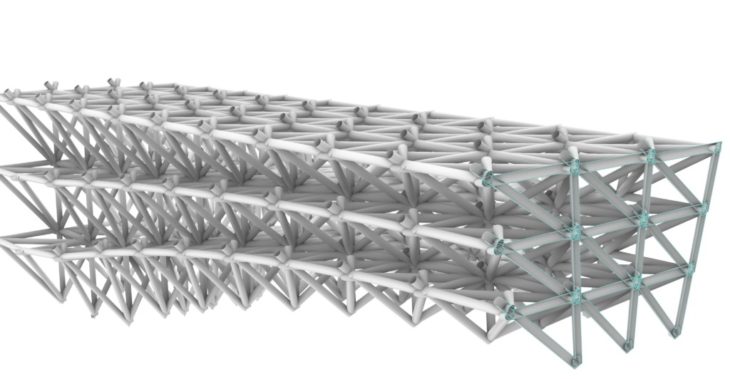
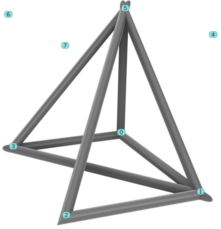
Defining Truss Members
The bounding edges from each cell in are extracted, and the remaining diagonals are generated using a pattern that follows the respective box edges and vertices as required to be able to print the structure by continuous extrusion. Note, the primary consideration for the direction of the diagonals is based on fabrication rather than, again structural predictability.
Generating planes at each vertex, we define the robot path and orientation. This then allows us to flexibly orient the robot to optimize the printing quality and strength and to avoid collisions between the robot and the surrounding printed units.
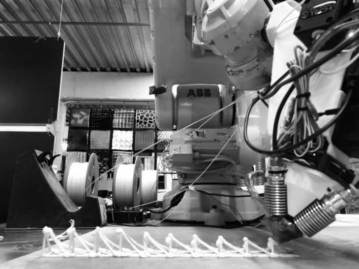
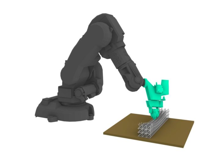
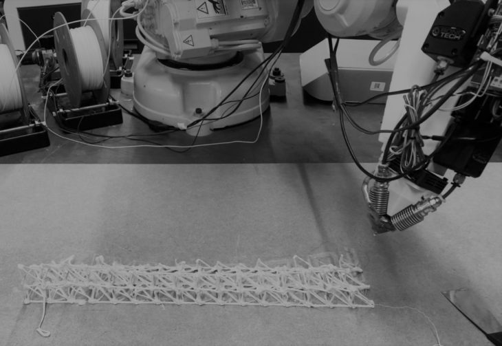
Fabrication
Fabrication is based on building the lattice of repeated units and stitching the ‘non-standard’ components with partial units at the open edges. The bridge is inverted for fabrication to allow the curved elements to be built in the air above the build table.
The core parametric cell has a lead-out point that matches the neighboring cell’s lead-in point. A string of cells can thus be printed by continuous extrusion effectively substituting each 3D box with it’s spatial lattice cell to create the 3D lattice structure. The parameters of the cell can be modified include changes to produce different overall geometries, in this case the transition from flat to arched surface.
The overall design can be broken down into a series of strings of cells, but the way in which one string connects to another string must also be solved in terms of a ‘locus’ or path that allows continuous extrusion to be used.
The solution can be described as all strings on one layer being printed in a zig-zag fashion. And how the transition is made from one full layer to the next must also be solved, and the solution can be described as the finishing corner of a complete layer becomes the starting corner of the next layer.
A Time Lapse of a 1x20 cell print can be viewed here
Unit Printing Strategy
The tool path for printing is generated by constructing a series of targets using a plane defied by each mesh vertex. By controlling the plane offsets and orientations at each vertex, it is possible tune the model geometry to compensate for material thickness and manipulate the robot to avoid collisions with neighboring cells.
Since the PLA is extruded as a relatively thick paste, through a 2mm nozzle, and the paths between targets includes a variety of movements in space, vertical rising movements, diagonal rising and descending movements, horizontal movements, controlling printing speeds, wait times, and fan states to allow for cooling and hardening of the material between targets is also required.
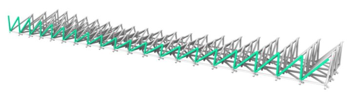
Bottom Layer
Bottom layer is built of sequential rows extracted by branch manipulation of the data tree.
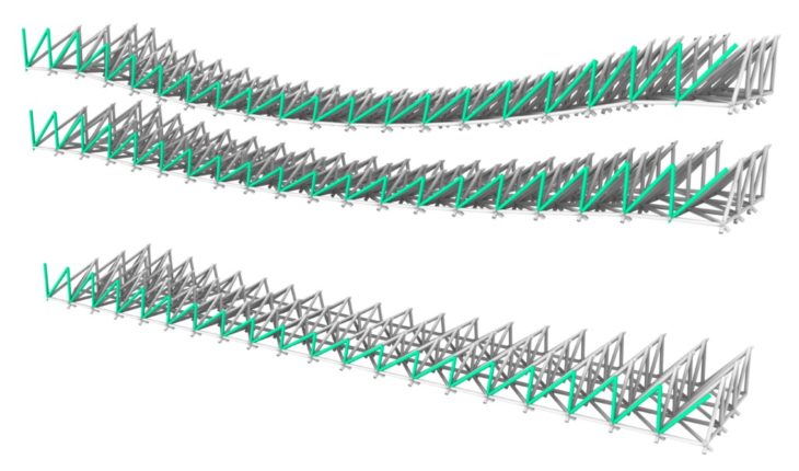
Bottom Layer with Stitching
In order to close up the last layer of each row and support the subsequent layer, a stitching is added to the last row with diagonal & vertical lines.
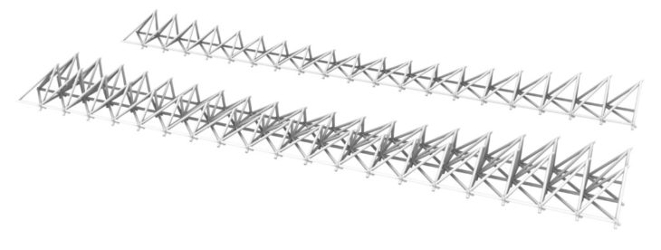
Layered Assembly
3 layers are stacked to create the final bridge volume
Prototyping
In practice much experimentation is required to perfect many details regarding the continuous extrusion process apart from the path to be followed. Another parameter that required much experimentation to improve results was the position and orientation of planes guiding the motion of the printer head. There were clear limitations on the possible orientation of the printer head to avoid collision with the structure itself, and these limitations vary at different places on the structure and at different stages of the build.
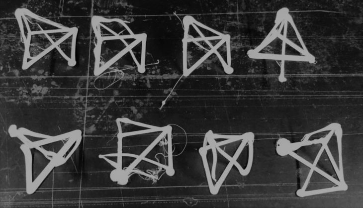
Initial experiments on individual cells.
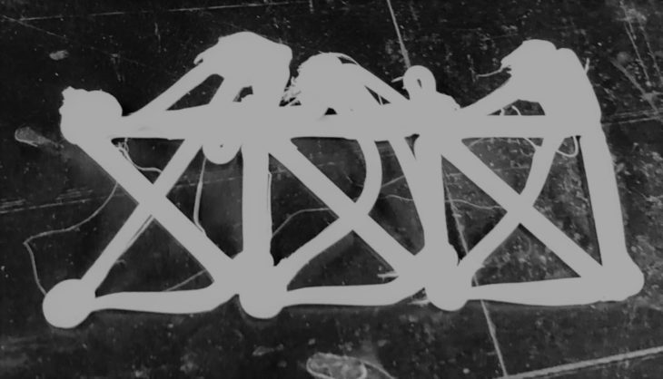
Experiments on connected cells.
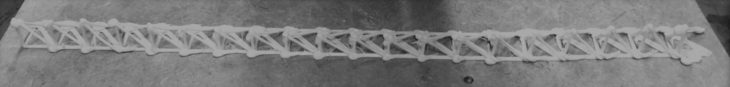
Experiment on full row.
Experimentation required a mix of deciding plane positions and orientations together with a selection of pause or wait times to allow material cooling. By experimenting and studying the results together while bearing in mind the mixture of plane orientations/move speeds/wait times that had been used, towards the end of the workshop a certain ‘sensibility’ as to what parameters were more likely to yield better results was beginning to be formed by the team members.
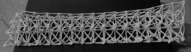
Final Printed Structure
LATTICE 03 is a project of IaaC, Institute for Advanced Architecture of Catalonia
Course: Masters in Robotics and Advanced Construction (MRAC)
Year: 2021-2022
Students: Alfred Bowles, Christopher Booth, Tomas Quijano
Faculty: Eduardo Chamorro, Marielena Papandreou, and Michael Dicarlo.