Understanding the possibilities of BIM beyond creating 3D models of architectural and engineering projects will open a world of possibilities for all actors involved in an architectural project. It can be an analysis, accounting or programming tool, and it is definitely a communication and collaboration tool. During the second term of the Master in Mass Timber Design (MMTD) course Tools, we have built a 3D model of an existing mass timber collective housing in Barcelona with Autodesk Revit: La Borda by Lacol.
Model overview
Students were organized in groups and assigned different tasks: Site and structure, facades, interior layouts, analysis and visualization, and worked together in a Revit model via the could. We were in charge of site and structure, and this is how our workflow worked:
Model Setup
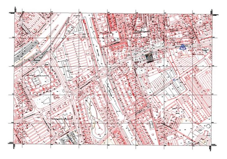
For the model location, coordinates were set using the inbuilt mapping service from Revit. The true north angle was set using the information available in the site plan background.
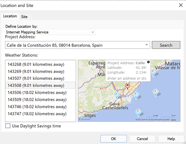
Model setup
Background files to be used as reference for our drawings were added to the site plan, floor plans, and sections as reference, PDFs were imported and scaled using graphical scales and “snap” functionality was activated. Reference elements like gridlines and levels were created using the information and backgrounds provided. Dimensions were added to these elements and distance between them was locked. After final coordination the gridlines and lever were pinned.
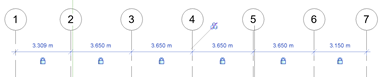
Guidelines
Property lines were placed using the information in the backgrounds drawings, and the survey point: was adjusted to reflect real world elevation above the sea level.
Different worksets were created to differentiate between the backgrounds files, site elements, structural elements in timber, structural elements in concrete, these worksets were set as non-editable.
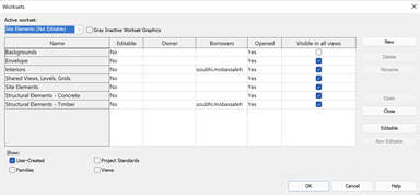
Worksets settings
Site modeling
After the Site Plan view and Workset were created, the modeling started by linking a CAD file from the city of Barcelona with city blocks and topography as a base.
Topography file from the city of Barcelona
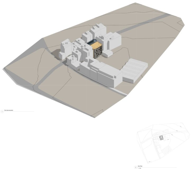
Surrounding buildings were modeled as in-place built components, using extrusions and void extrusions and assigning the correct heights (Level 1 = 14,89). All surrounding buildings were classified as “Existing” in the Properties Palette. The topography was modeled using a Toposurface which was Split to create the sidewalks, and a building pad was placed under the building. The toposurface was later adjusted around the building.
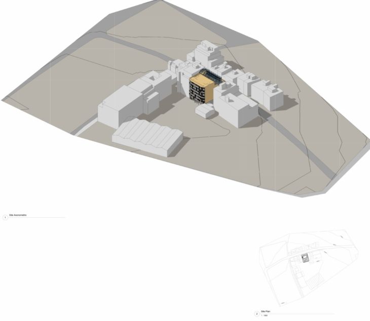
Site overview. Axonometric and site plan
Structure modeling
The building has a concrete structure in the basement and ground floor, and a timber structure in the upper levels. After the model setup was ready, the As Built Structural Set of Plans were used for reference, different elements were created such as the foundation slab, reinforced concrete columns, beams, and retaining walls.
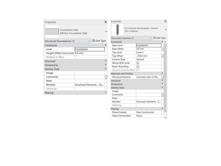
Concrete structural elements
Following the levels of the project, from the second level upwards it’s a CLT and Glulam structure. Most of the CLT walls on the second and third levels are CLT C24 120mm, while in the rest of the levels are CLT C24 100mm. The double-height space on the second and third levels is built from Glulam columns and beams. The beams were aligned in the proper position and were assigned the corresponding specification depending on the level at which they are located.
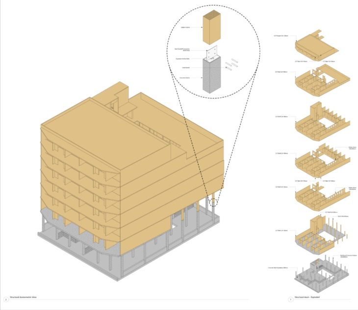
Axonometric and exploded axonometric of the concrete and timber structure
For the staircase, as well as other structural elements, external references(.dwg) were used that provided us with the exact measurements of the modules.
Building the staircase with external references
Drawing documentation
Finally, we created layouts to document our work.
- Titleblock: Family file for the titleblock was adjusted
- Sheets: were created in reference to required information from site and structure
- Site Plan and Axon:
- A 3D axonometric was created for the site overview.
- The Visibility/Graphics menu was used to hide elements from other worksets in the view. Also Hide in View option
- Texture, shadows and lines were adjusted with Graphic Display Options menu
- The view was placed on a sheet, scale and title adjusted
- A site plan was created, using the same workflow (adjusting the existing site plan view) and placing it on the presentation sheet
- Structural Plans:
-
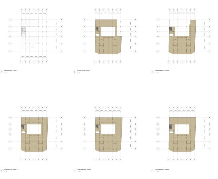
Structural plans
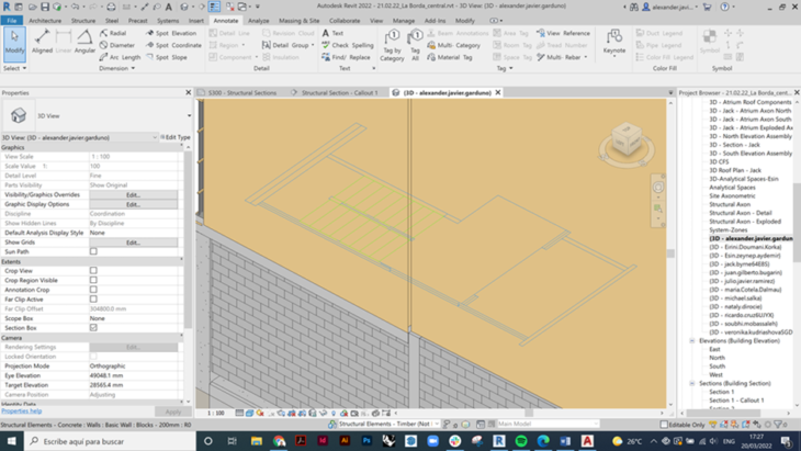
- Structural Sections:
- -Two sections were created, one longitudinal and the other transversal, scale 1:100
- -From a section a 1:25 callout was made (facade cut)
- -A 1:10 callout was made of the connection between the wall and the CLT slab with its metallic connector.
- -Only the structure workset was used
- -Hide structure elements that were not relevant to the view
- -The switch join order was changed to remove the finishes of the structure
- -The views were inserted in Sheet to start detailing the documentation.
- -The color of the structural elements and the style were homogenized.
- -Details 1:25 and 1:100 (CLT Hatch) were detailed with 2d resources
- -Specifications were inserted inside the sheet
- Structural Axons:
- Views were created
- Structural worksets were isolated
- Revit and CAD links were turned off
- Model parts were created from deck assemblies and non-structural parts were hidden
- Elements were grouped and displaced to create the exploded axon view and detail
Annotations were added to the drawings
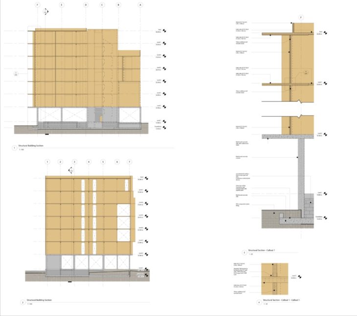
Detail section
The site and structure group was critical for setting up the model and its work was taken further by the colleagues in the facades, interior layouts and analysis groups.
La Borda: BIM collaboration via cloud services is a project of IAAC, Institute for Advanced Architecture of Catalonia developed for MMTD in 2022 by students Julio Ramirez, Juan Bugarin, Alexander Javier Garduno Sanchez and Maria Cotela Dalmau. Faculty: Michael Salka. Course: Tools