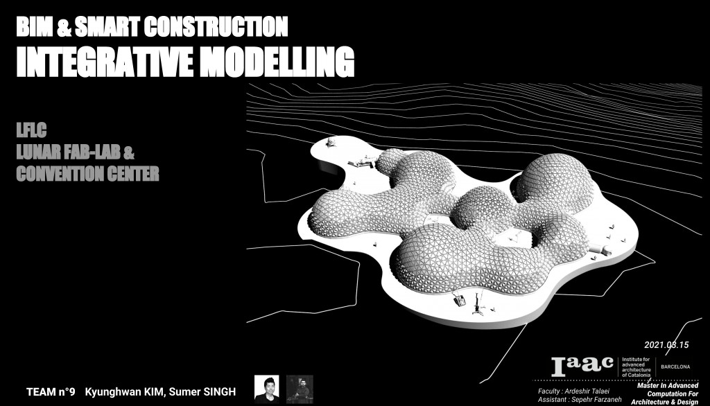
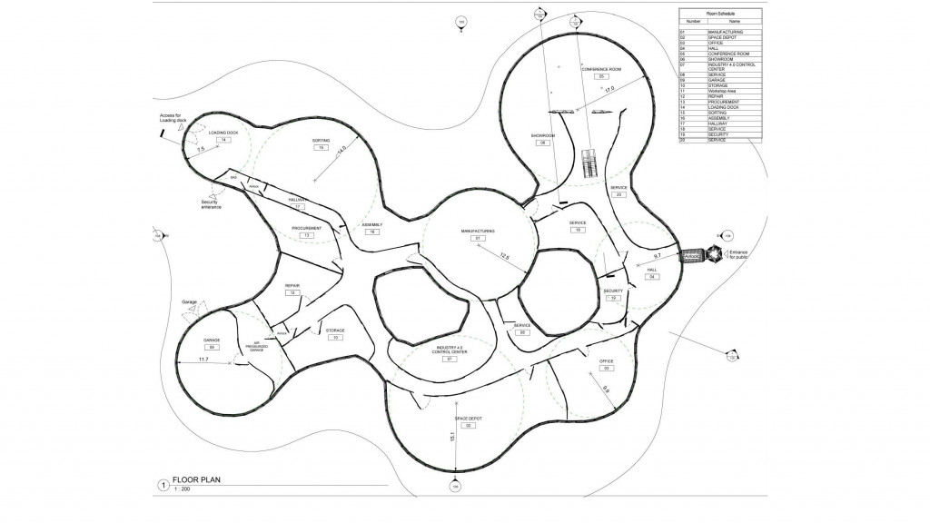
 The LFLC (Lunar Fab Lab and Convention Center) project within the Integrative Modelling course was a natural fit for the adaptive components features inside of Revit. In order to fully use the collaborative potential of Rhino inside Revit, we explored form finding and iterations inside Rhino/GH, created a single adaptive component panel family inside Revit, applied all the panels to the form inside GH, and then brought into the Revit environment for further detailing, diagrams, and drawing creation. Within Revit, we were able to create panel composition details, lists for panel details and quantities of the different types of panels, exploded axonometric views, floor plans, sections, elevations, and isometric views. By using the Rhino inside Revit feature, we were able to truly harness the collaborative power of the 2 powerful softwares: Rhino/GH and Revit.
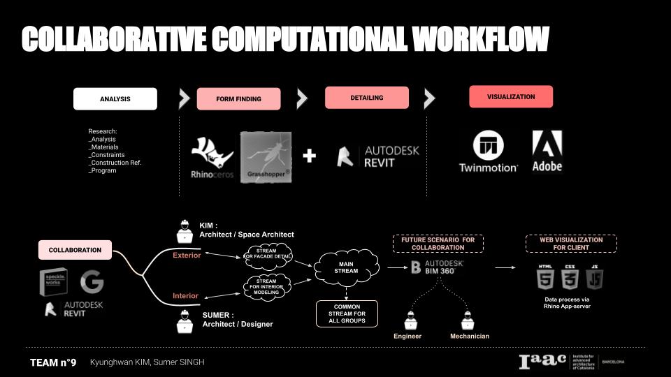 The collaborative computational workflow for the project started with the Analysis of the project using any means necessary. The form finding was done using Rhino and GH and the detailing in Revit. The visualization was finally done in Twinmotion, Maya and Photoshop.
Here, Rhino & Grasshopper were mainly used, then those data was transferred into Revit through Speckle tool and Rhino.Inside.Revit(R.I.R). The data was used internally between the 2 group members. This fed into the main overall studio stream. In the future we see ourselves using BIM 360 and also creating interfaces for clients using web visualization tools. At this blog page, we are going to mainly talk about how was the working process of Rhino.Inside.Revit going for the Lunar Fab-Lab Convention Center(L.F.L.C). If you want to find out more detail for this project, click the link below!
See the project of the L.F.L.C Project, ‘Click’ !!
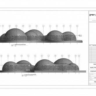
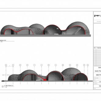
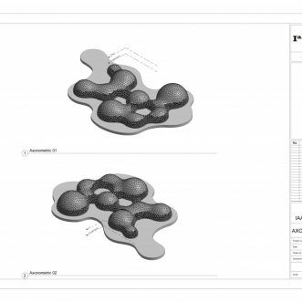
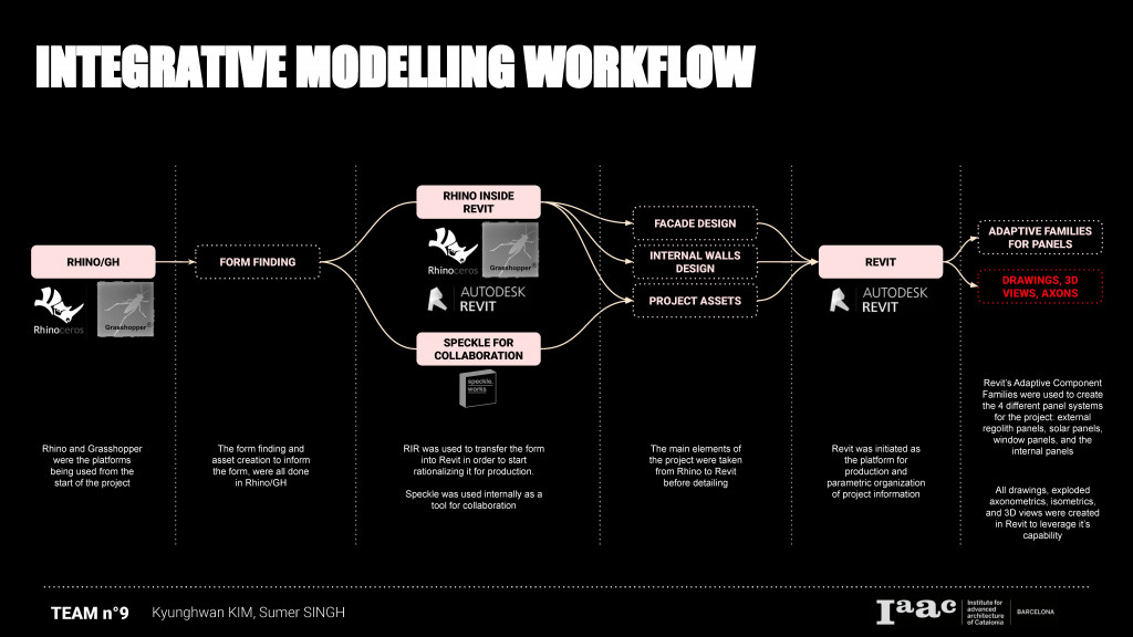 The integrative modeling workflow started with Rhino/GH for form finding, detailing using both R.I.R and Speckle, and then finally using the Adaptive family capability inside Revit for the Panels, and also to produce the Drawings, 3D views and axonometric views.
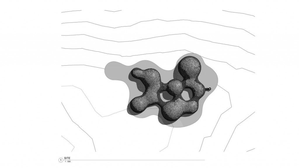
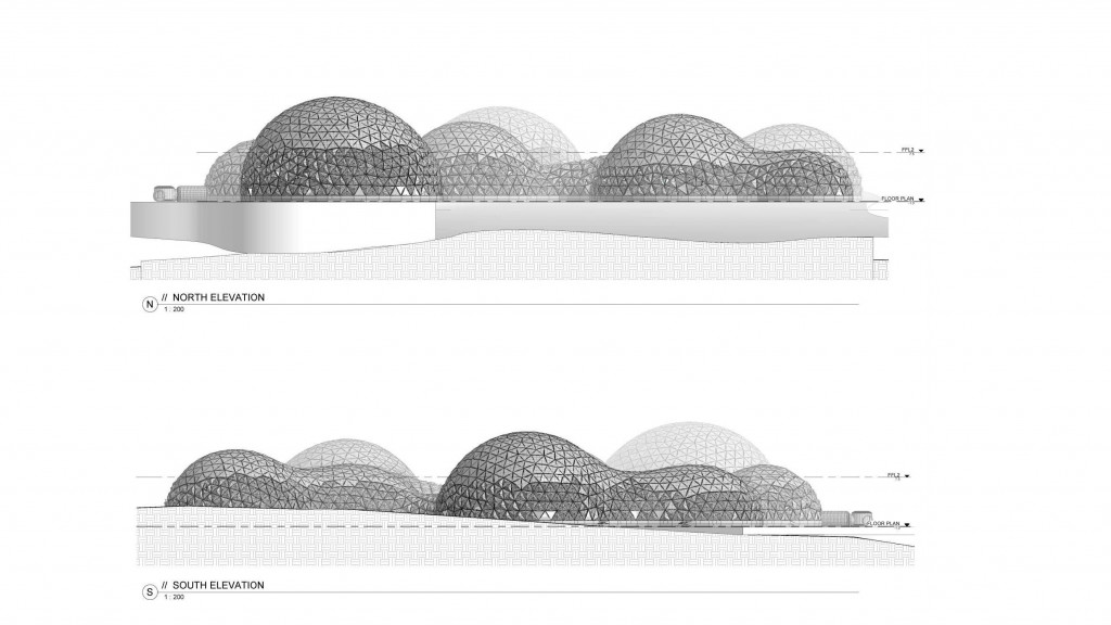
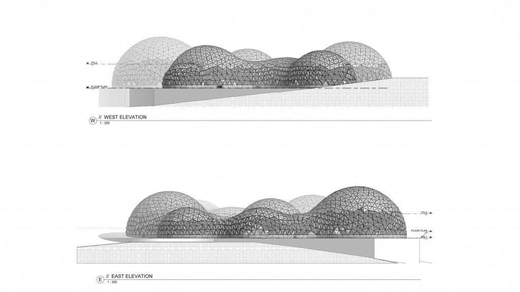
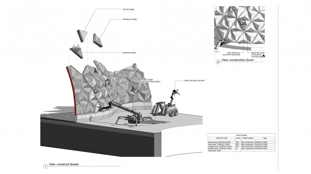
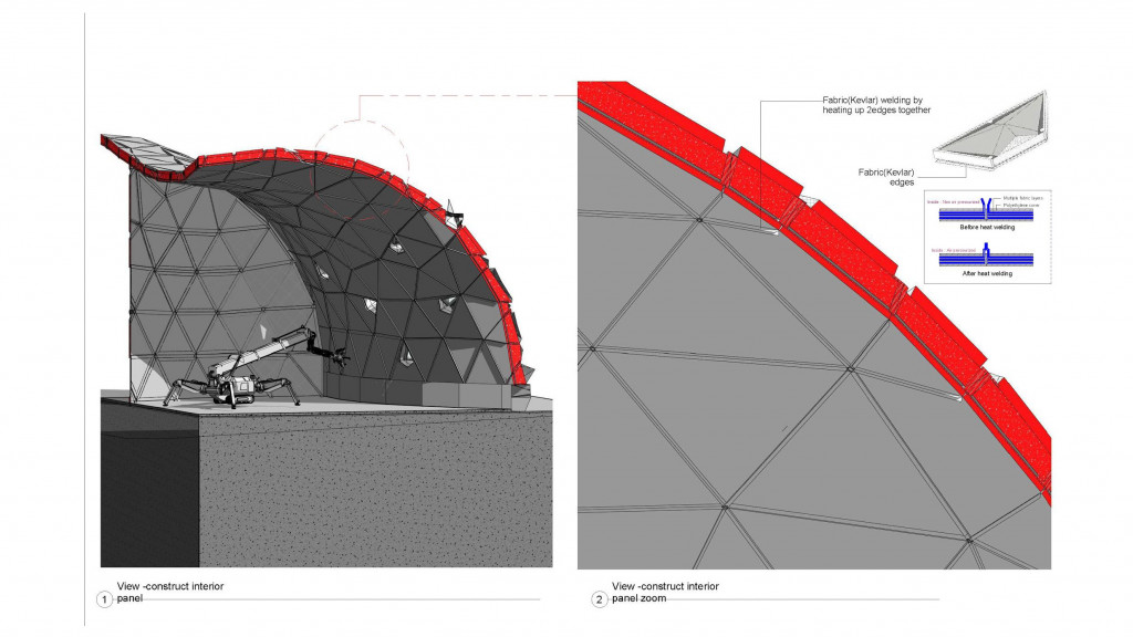
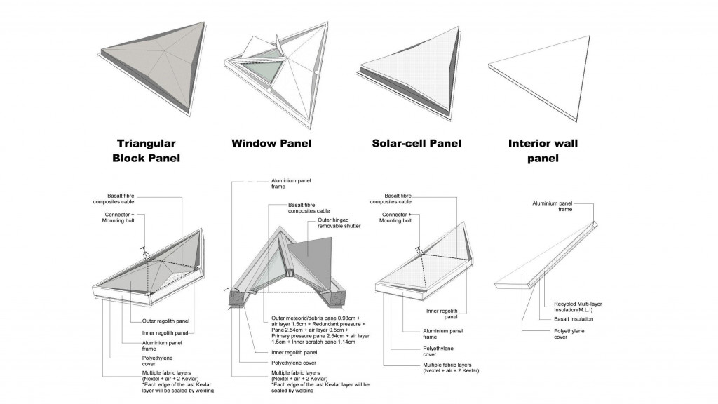
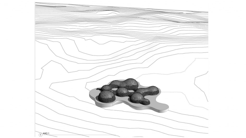
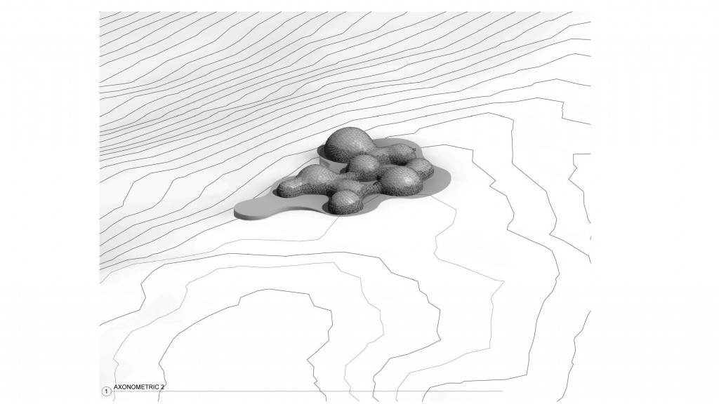
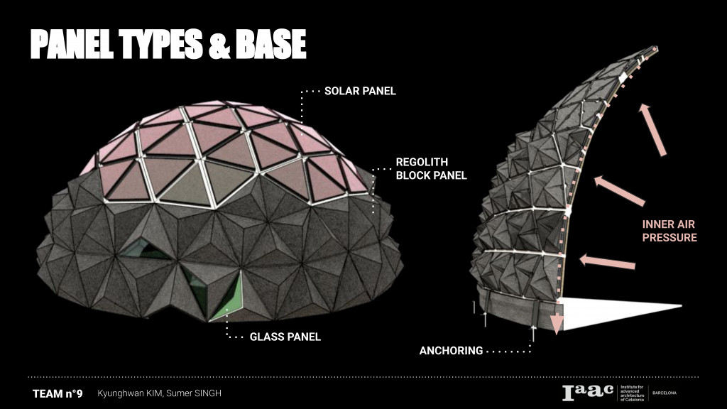 As you can see at the image above, the L.F.L.C has a simple dome geometry because of supporting inner air pressure in the low gravity (1/6 of Earth). The inner air pressure is 14.7 psi because, if it is too low like skylab or sâce shuttle, it has an advantage of less inner force and it takes less time to depressurized for crews when we go outside. Inner fabric material of Kevlar can be welded to keep inner air pressure. For the outer shell, we have 3 different panels for outer wall of the dome. The three triangle panels are below ;
- Solar panel : Electricity for self-sustainable architecture
- Regolith block panel : Reduce space radiation (SPE, GCR)
- Glass Panel : Giving an opportunity to observe outside not only for the security reason but also, for the psychological comfort. However, not too many windows because of radiation. Each windows will have attachable aluminum shutters.
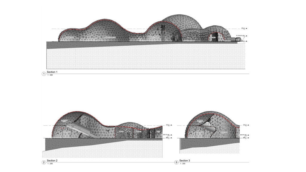
In stead of having big concrete foundation which is ineffective and can be risky, we choose a anchoring system to fix the dome.Furthermore, the weight of regolith panels would add self-weight of building to fix on the low gravity environment.
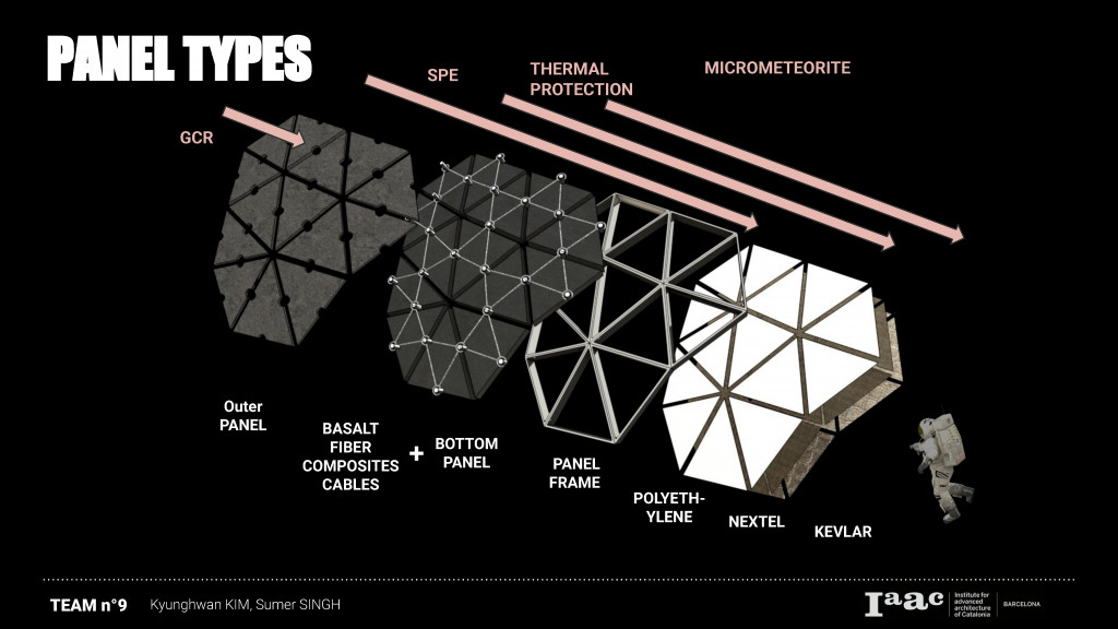 Each panel has a basalt fiber composites cables between 2 layers of regolith panels. Every fiber composites cables are linked together. This can be successfully used in compression and bending active structures as well as in tension active structures. Basalt based materials are environmentally friendly and no hazardous against pure lunar regolith. The fibre extruder will build to draw 30km of 30um diameter fibre from the reservoir, metal coat it with calcium and wind around a collecting reel. It may use 75kW thermal solar concentration. Tensile test on a 25um fibre indicated approximate strength of 5000kg/cm2 which is equal 70,000 psi. The regolith panels are fixed by panel aluminum frames which is covered by polyethylene at the bottom. Then in side there are Nextel for thermal protection and Kevlar for the protection against micrometeorites.
So, the biggest question that we had was how to send this complex panel system which counts over 5,000 panels into Revit. The main reason to use Revit was for detailed architecture drawing for our future collaborators or fabricators.
First test with ‘Speckle’ was successful. Although, we had a number of panels, it was fluent to send geometries data into Revit from Grasshopper. However, we couldn’t give family information for different 3 panels. In other words, they were inserted as a just ‘geometries’, not as a panel or wall. It was complicated and heavy because each layer of panel was inserted into Revit.
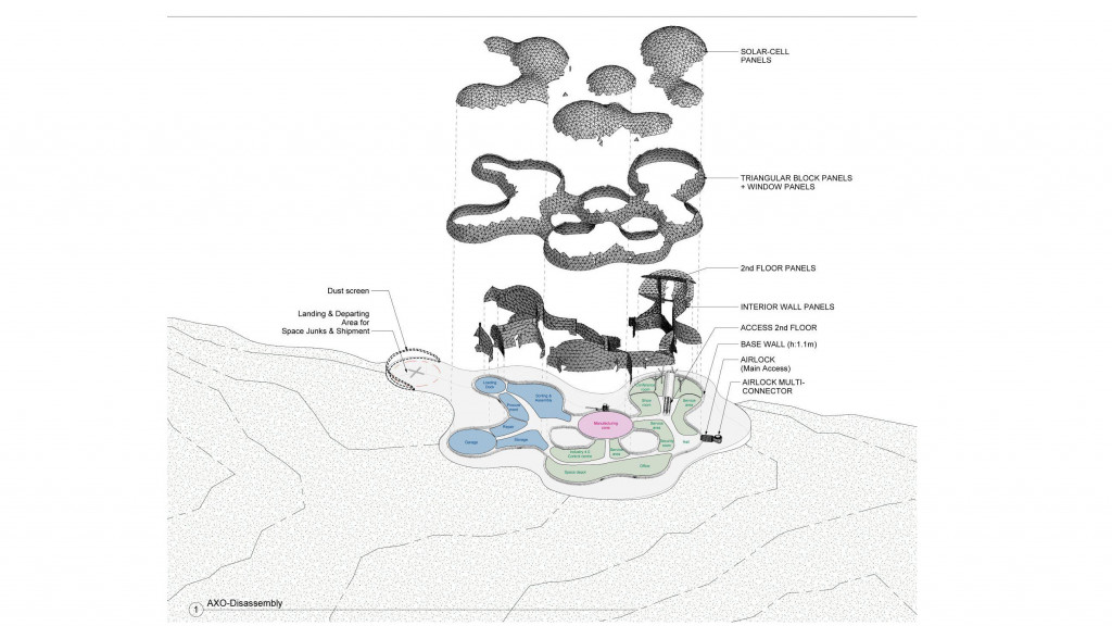
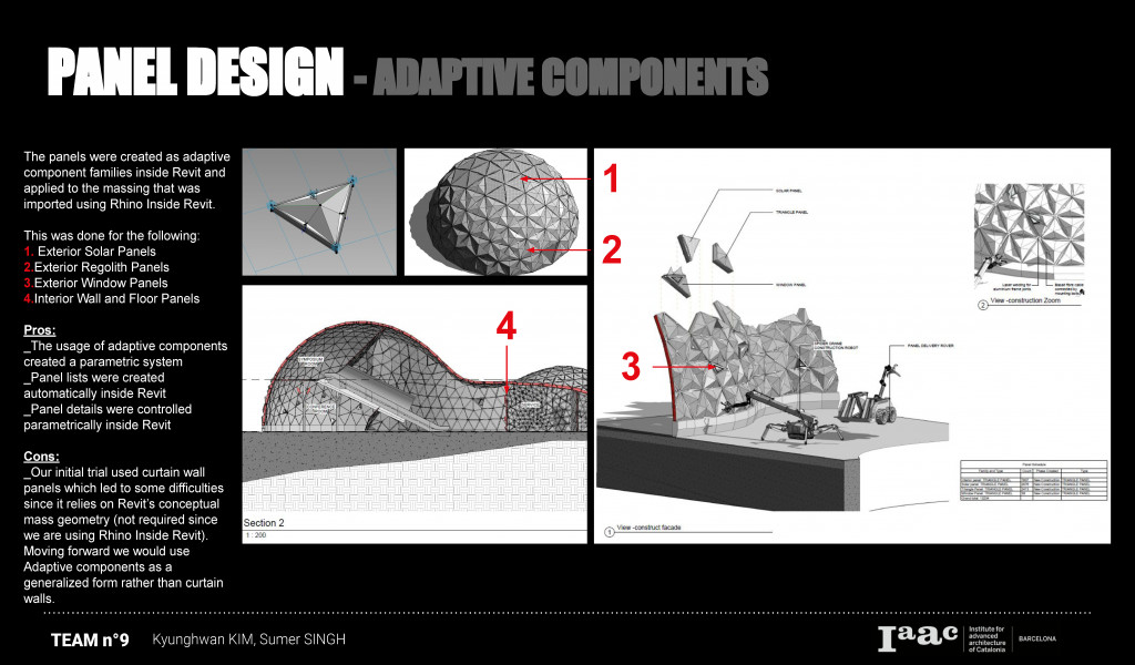 Therefore, we had to remodel our panels in Revit by using ‘adaptive family’ function. Consequently, we could have a number of each type of panels and it was easy to control each panel for axnometric.
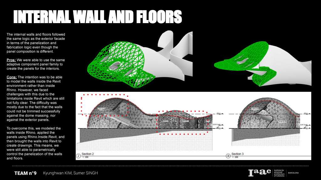 A single adaptive family was created and then applied to different types of the panels that make up our building: exterior solar panels, regolith panels, window panels and also the interior wall and floor panels. This was a big advantage of using the adaptive family components inside Revit by being able to vary the thicknesses and compositions. We were also able to create panel lists and quantities for the different types of panels.
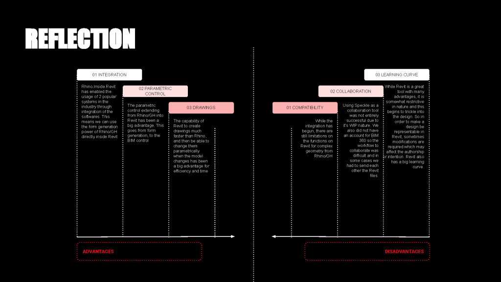


 In conclusion, Rhino.Inside.Revit was very useful to work between Revit and Grasshopper. However, if we could start from Revit first instead of Rhino, it might give us more efficiency of working flow. Because first of all, Revit offer more various and easy method for high quality visualization. Second of all, if the final document will be done in Revit, it is more easy to modify Revit geometry in Grasshopper then send back to Revit thanks to the function of family and material quantity sheet in Revit.
Students: Kyunghwan Kim, Sumer Matharu
Faculty:Ardeshir Talaei
Support: Sepehr Farzaneh