IVY DATA-DRIVEN IMMEDIATE ASSEMBLY
Data-Driven immediate Assembly is a project developed during the Software I Seminar of the MRAC-20/21-program. The task was based on developing a pavilion or similar structure based on a sensible data. The structure should be generated from small components using grasshopper aggregation method and Anemone was used for this design approach.
Design approach & Data Collection
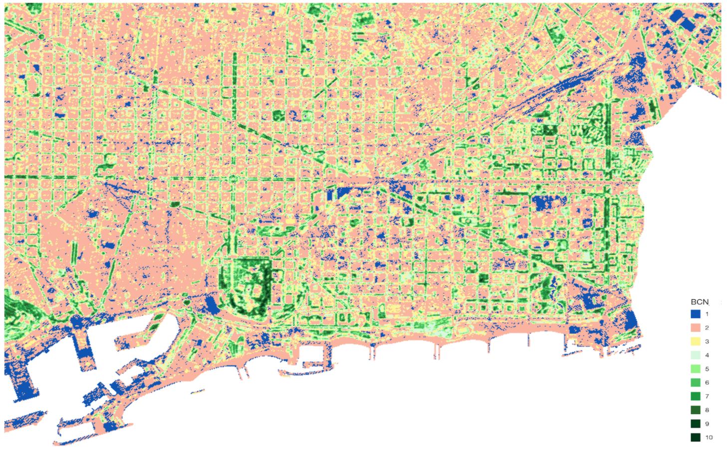
This project focuses on design generation using sensible data, NDVI (Normal difference vegetation index) data of Barcelona was decided to be collected.
The aim behind using the NDVI data was :
- To create components for aggregation.
- To use data to create design patterns within the aggregation. ( various outcomes can be achieved depending on the different locations in the city).
Data input and processing
NDVI data were collected from the OPEN data BCN website.
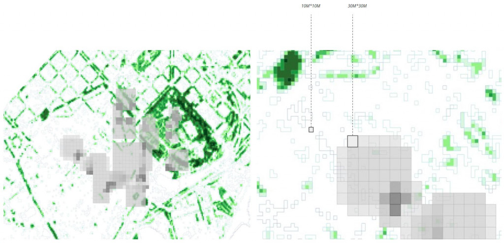
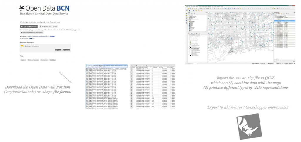 The data was then imported in Rhino 6.0 over the Barcelona city map so as to generate the NDVI color map. The NDVI data were further processed in Rhino. Then we extracted basic component geometries from the NDVI map, a total of 7 geometries extracted.
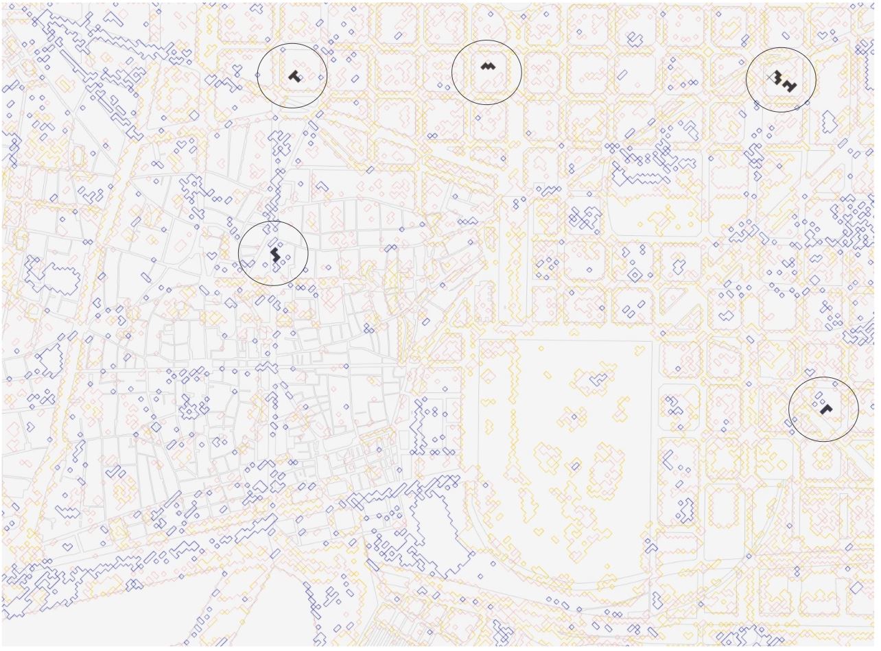
NDVI Map outcome (imported in Rhino)- Highlighted geometrical shapes extracted from NDVI map
Component generation, aggregation logics, and aggregations
After the import of NDVI data in rhino, we observed several geometrical shapes and extracted them to generate basic components
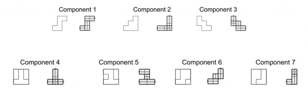
First basic components generated (Above)
We extracted selected geometries from the NDVI data then transformed basic shapes so as to create interlocking assembly and better architectural outcomes. With each transformation, we tried aggregations to create meaningful outcomes.
First Component Transformation from basic with interlocking logic (Above)
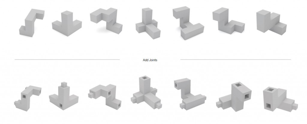
Based on the components generated, we created grasshopper logic. Each component has multiple male (outgoing) and female(receiving) connectors. Male and female connectors connect with each other in the logic to create a shape/outcome. Below image, first aggregation outcome from the above mentioned components.
First Aggregation (Above)
As the above components were very basic in shape. So we further modified them so as to to create better interlocking, use the NDVI data in the components, and to generate better aesthetic outcomes
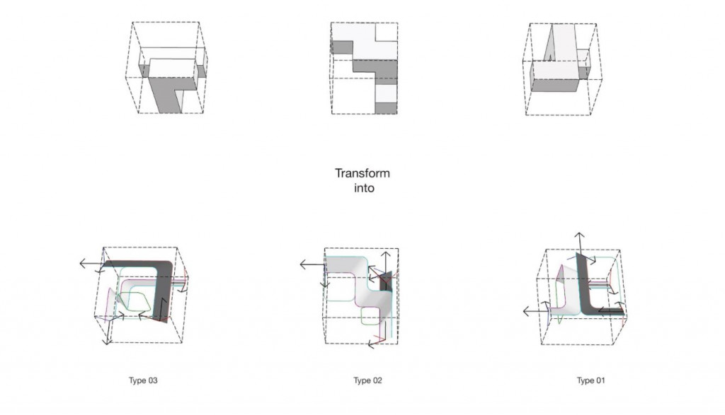
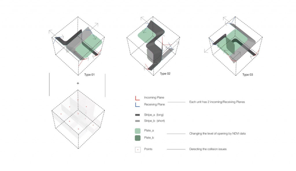
Component Transformation (Above)
With the new modified components, we tested different/several logic. First, a few aggregations were not satisfactory. The aim was to generated uniformly spread aggregation.
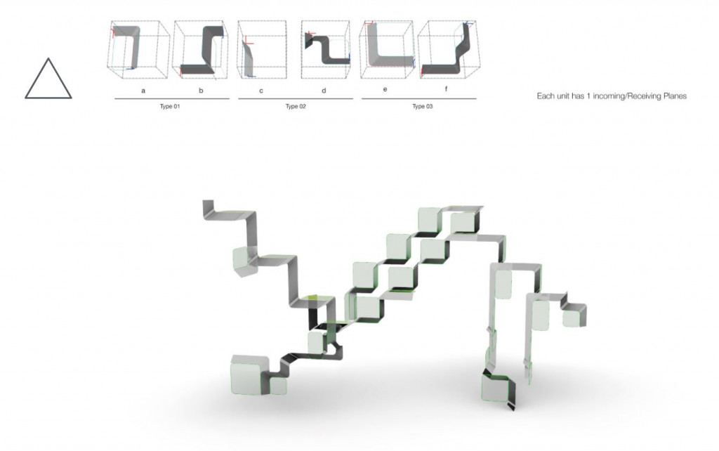
Second Aggregation Logic (Above)
In the above aggregation logic, each component unit had 1 incoming/Receiving planes. This logic was not satisfactory because it generate a linear outcome which didn’t meet the design expectations.
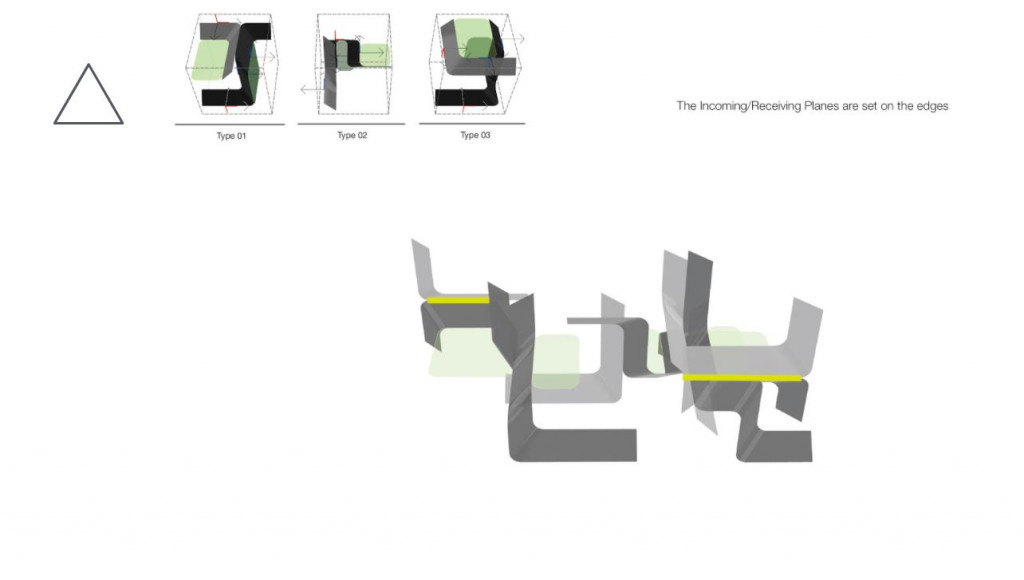
Third Aggregation Logic (Above)
In the above aggregation logic, the incoming/receiving planes assigned on the edges. This logic didn’t meet the expected outcome.
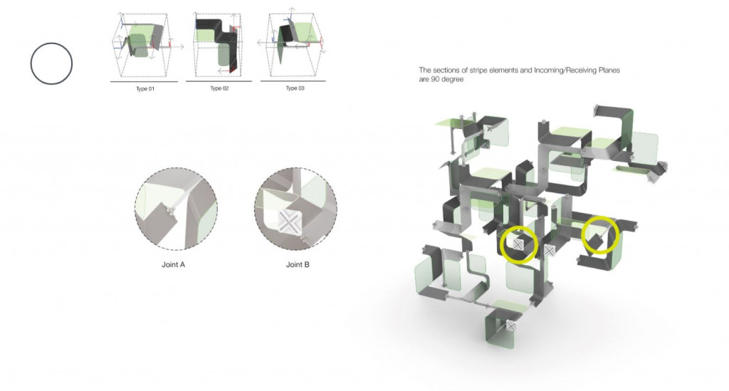
Fourth Aggregation Logic (Above)
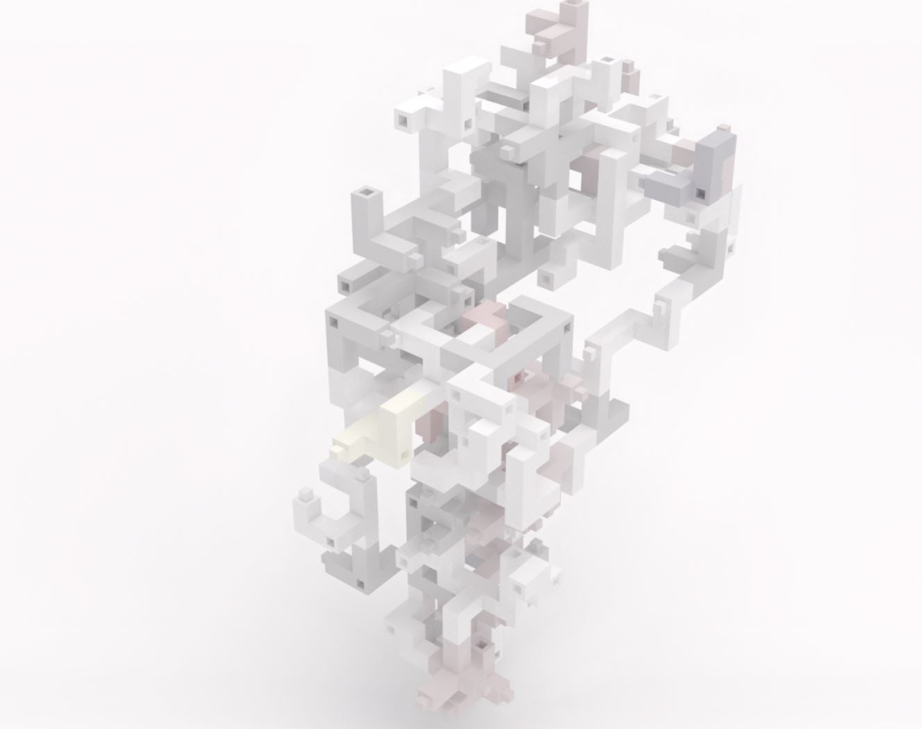
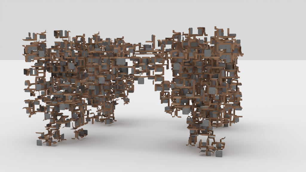
The incoming/receiving planes assigned on the edges, 90 degrees to each other. Result of which outcome generated were much uniform in all directions. Final aggregation generated after component design, logic completion.
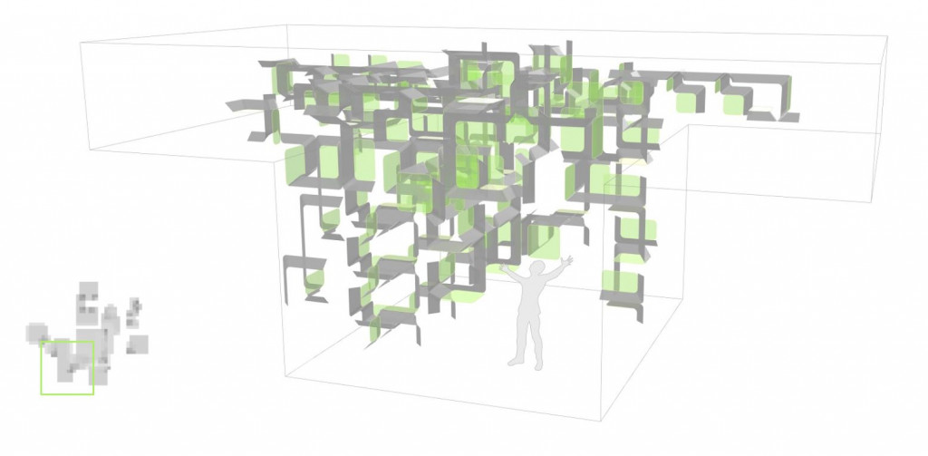
Final Aggregation (above)
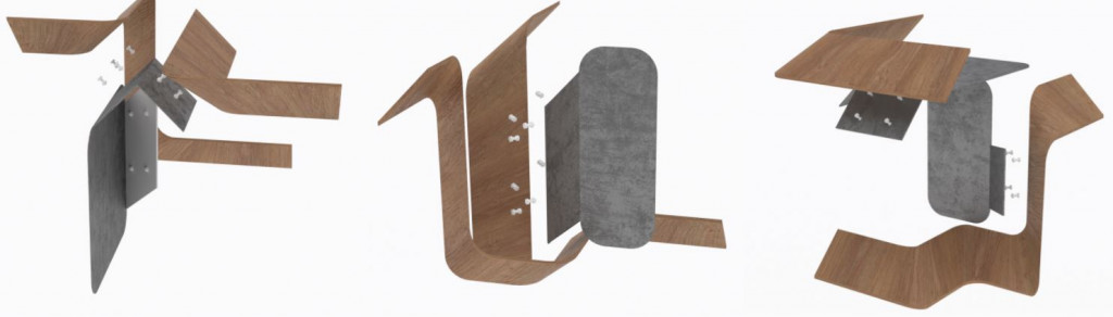
Materiality
Each component consists of 2 parts,
- Flat plate- built using the metal sheet.
- Bent section- built using wooden sheet/plywood.
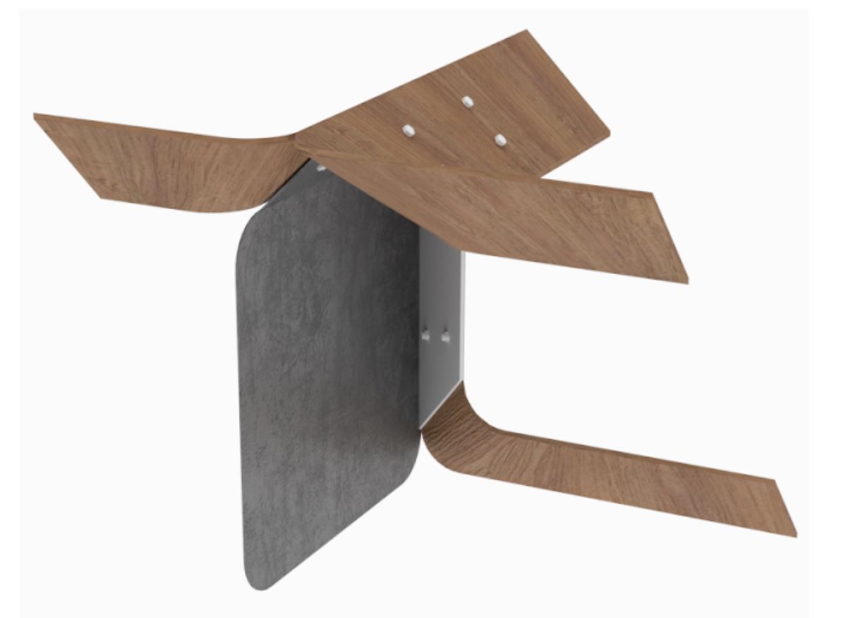
Material render of component
Connection details (within component)
Each component is a combination of 2 elements;
- Flat plate (metal sheet).
- Bent element (wood) which are connected using the bolted connection.
Connection detail (within component)
Connection details (Component-Component)
As per the logic, one edge of the component connects with other at 90 degree flip. Metal connector with bolt inserts was designed so as to keep the connecting components hold together (below image). Each connecting edge of the component have slits in order to enable overlap.
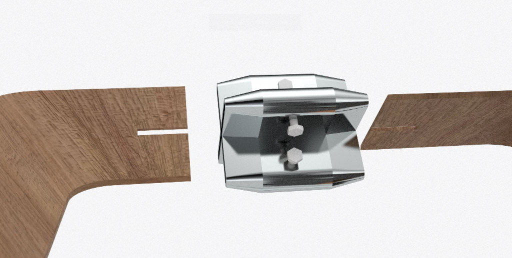
Connection detail between component using metal connector
Final outcome
After completion of components design, aggregation logic and connection details the final outcome generated has a high potential for improvements. Eg. Use of NDVI data in a much dynamic way is possible in this design.
Ivy-Data driven immediate assemble is a project of IAAC, Institute for Advanced Architecture of Catalonia developed at
the Master in Robotics and Advanced Construction in 2020-2021/22 by
Students: Charng Shin Chen, Arpan Mathe.
Faculty: Ján Pernecký, Eugenio Bettucchi
https://github.com/MRAC-IAAC/IVY-DATA-DRIVEN-IMMEDIATE-ASSEMBLY-SOFTWARE-I-SEMINAR