Incorporating thermal performance in clay 3D printing
Controlling Thermal conductivity in clay 3D printed structures by applying L-system logic to infill patterns.
The introduction of 3D printing technology into the design profession has brought new means for architects to design and manufacture their designs.
The creation of a 3D printed object is achieved using additive processes. More specifically, 3D printing or additive manufacturing is a process of making three-dimensional solid objects from a digital file. In an additive process, an object is created by depositing successive layers of material until the object is created. Each of these layers can be seen as a thinly sliced horizontal cross-section of the final object.
Therefore, by designing how the material is organized and deposited in each of these layers, we can incorporate various types of performances (structural, environmental) in our design.
As the field of interest of this research is large scale additive manufacturing with natural materials, the added value of incorporating performance by design is greatly enhancing the already low cost benefits of using local natural materials, like clay, and the ability to use big industrial robots to print directly on site. All these elements, as they come together, challenge the contemporary architectural thought and construction processes, and introduce a paradigm shift in the construction industry
2.Problem Statement
Most 3D printing slicing softwares applied in desktop 3D printing use specific geometrical patterns (rectangular, triangular, wiggle and hexagonal or the honeycomb) as a way to connect the perimeters of a 3D printed model together by creating an interior structure. These layers of material are called infill. In standard 3D printing the most common patterns that are used are linear, honeycomb and rectangular.
As we move away from traditional desktop 3D printing and step into the realm of large scale 3D printing with large scale robots, in particular industrial robot arms, and the use of materials common in modern age construction, like clay, ceramics or even concrete, infill offers the potential to be be augmented with intelligent design. Hence, infill patterns in large scale 3D printing, by design, can take an active role as a (strong) structural element that bonds the structure together, as well as incorporating performative characteristics that augment the thermal performance with respect to a traditional wall. Therefore, in this line of research, the aim is to achieve control over the conductivity of a wall, thus control the thermal lag.
In more detail, the research studies how thermal properties can be embedded in the wall section through the intelligent design of the infill and more specifically, the potential of controlling thermal lag, by controlling the conductance. This can be achieved by exploring the relation between different infill patterns and the hollow cavities filled with air within the wall.
_Explanation of phenomena: What is conductivity
Generally, based on the second law of thermodynamics, heat flows from hotter to cooler in order to achieve equilibrium.
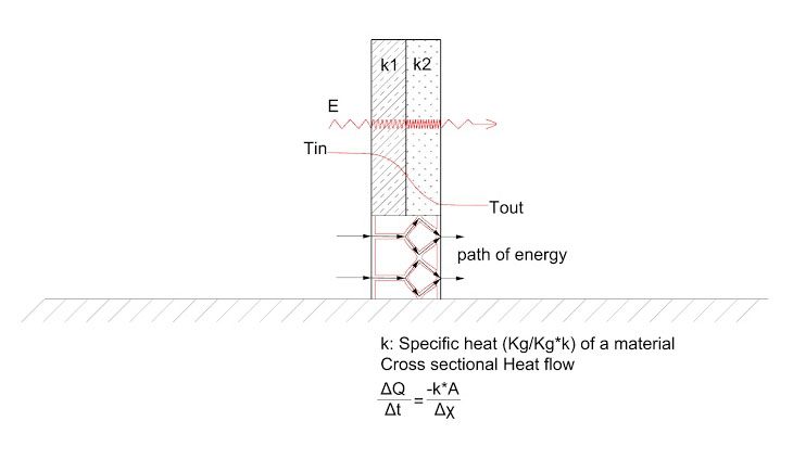
Therefore we can say that Thermal conductivity is the ease with which a particular medium conducts. Conductivity is measured in W/mk, (watts per meter kelvin) and is related to the quantity of energy that is transmitted in a determined time period, through a material thickness, in a direction considered normal with respect to a temperature difference.
_Key parameters
a) Material density is expressed by the specific temperature (k) of the material and acts as resistance to heat transfer.
Therefore, we can control the time lag that energy from a receiving surface is beginning to be perceived on an emitting surface.
b) As conductivity is explored in 3D printing based manufacturing, the material deposition inside the width of a wall is controlled, hence, by design, the thermal lag is altered.
In this case, the parameter controlled is the pattern that the robot toolpath follows to print, while keeping constant:
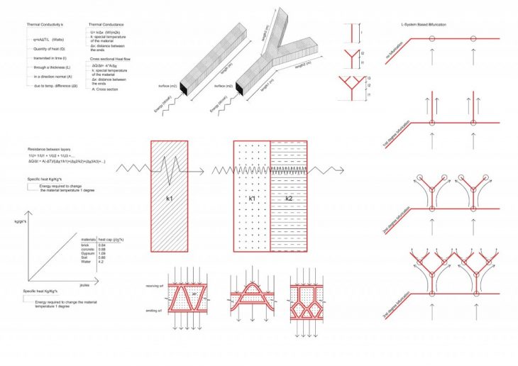
i) the specific heat of clay (k1= 0.80-0.84 kg/kg*k) and,
ii) the surface normal based on extrusion width and layer height.
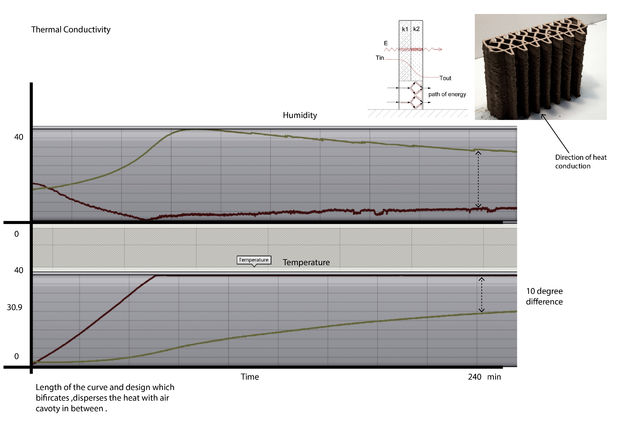
Therefore, the time lag between the receiving and emitting srf can be regulated by managing the length of the path and the surface area that it conducts.
A longer path, and more bifurcations on this path, relate to more ways for the energy to travel and disperse within the wall thickness. Fractal geometry in general is considered efficient for managing conductivity, therefore, an L-system bifurcation pattern has been taken under consideration
Research Hypothesis
a)Iteration diagram
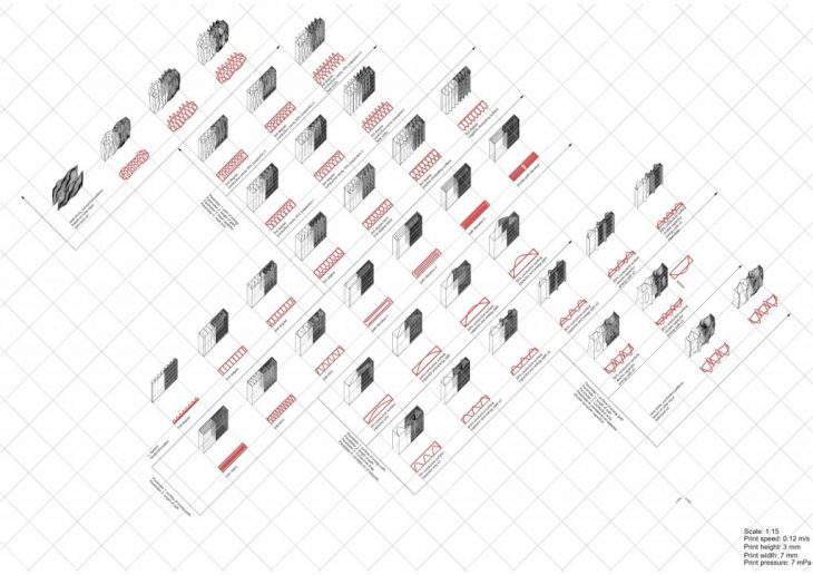
The next step was to form a chart of concept geometries and control conductivity by design.
- infill/ length of the path
The first set of iterations are based on infill patterns, where the key parameters are the surface of the energy path and the length of the path itself. The geometry is based on the idea that the longer the path, the greater the time lag and lesser the conductivity. - L-systems
Furthering this concept and applying fractal logics, visual feedback on how to manipulate energy flow inside the wall can be developed. L- system bifurcation therefore provides a good visual feedback on the amount of branches and the paths that the energy travels within the wall. - heat sinks_capacitors
In the most complex iterations, two more parameters were explored:
the idea of the heatsink, as a geometrical form with main purpose of accumulating heat and distributing it;
the idea of the capacitor, that acts as a heat buffer and as an active delay to the energy transfer.
Both these concepts exemplify how conductivity can actually be expressed in form and function architecturally.
Hence, when speaking about conductivity, the aim is to control time by manipulating geometry. To achieve this a standard infill pattern may be a good option in terms of conduction, however this does not allow to take advantage of thermal lag.
These last two geometries incorporate all the parameters proposed earlier as well as incorporating heat sink and capacitor logics, therefore potentially perform more efficiently in terms of thermal lag (zoom in iteration diagram).

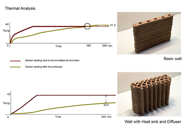
b)physical testing
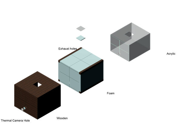
In order to test this specific research hypothesis, a thermal simulation machine was built. The machine consists of two parts: one side of the machine allows to simulate, different environmental conditions using a heat a lamp and a humidifier. In the middle, a scaled model of a wall acts as a barrier, while on the other side of the box a series of sensors connected to an Arduino board transmit data based on temperature and humidity. With this data, the goal is to test the thermal performance of a given design.
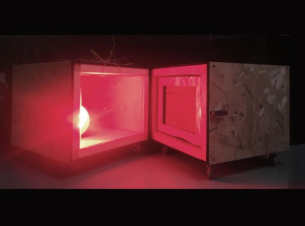
Based on data from the test, some of the designs exhibited temperature difference in the range of 10 degrees over a period larger than 240 min. Hence, the hypothesis stands, by incorporating intelligence into the design of the infill thermal performance can be achieved. The outcome is that, by manipulating these two parameters, one can say that the conductivity of a given wall can be regulated and by that, the thermal lag during a day-night cycle can be regulated.
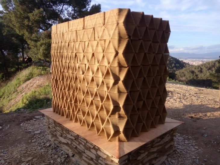
Case study Terra_Performa
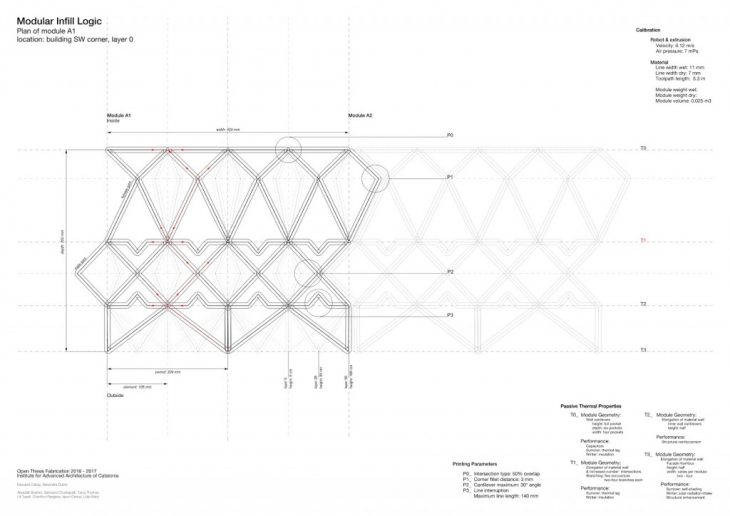
The conclusions and knowledge that derived from the physical testing and digital simulations, were introduced into a 3D printed performative wall design prototype, as presented in IAAC’s research project TERRA_PERFORMA. The parameters that were used in the design were:
- closed air cavities as an insulator,
- branching infill patterns that control the path of the energy that is being transmitted through the width of the wall.
The section of the big scale 3D printed wall can be divided into 4 specific layers:
- the outer perimeter of the wall,
- infill,
- hollow cavities,
- the inner perimeter of the wall.
The outer perimeter of the wall was optimized for solar radiation in order to welcome winter sun rays and achieve maximum penetration and to provide self-shading during summer and have more cool areas on the surface of the wall. This way, during winter the conductivity of the facade is maximized as there is maximum penetration, also, in comparison to a straight wall, there is a 436% rise in total radiation.
The interior infill is divided into two zones, one zone mostly optimized for structural performance and some thermal optimization, as there are small closed cavities that act as insulation, and one zone that is optimized only for thermal performance. In this zone there are large cavities of stagnant air, that, along with the branched infill, both greatly increase the thermal lag of the wall.
Finally, based on the assumptions explored by design, and the results from physical testing and the case study 3D printed wall, the longer path, with more bifurcations relates to more ways for the energy to travel and disperse within the wall. Hence, this design maximizes thermal capacity, minimizes thermal conductivity and maximizes thermal lag.
Also by incorporating cavities of stagnant air (insulators) the thermal mass and the thermal lag of the wall is also greatly maximized.
These geometries and more specifically, the ability to control matter on that scale, can only be achieved thanks to the precision of 3D printing technology, giving the necessary liberty to integrate the parameters presented and examined above into the final design and construction.
References:
-
https://sustainabilityworkshop.autodesk.com/buildings/thermal-properties-materials
-
http://www.reidsteel.com/steel-buildings/eco-friendly/thermal-mass-in-building
- Perry, R. H.; Green, D. W., eds. (1997). Perry’s Chemical Engineers’ Handbook (7th ed.). McGraw-Hill. Table 1–4