This blog posts charts the explorations of mesh topology made towards a pavilion for the final presentation of the Software I seminar in the first term of the MRAC course, tutored by Andrea Graziano with assistance from Eugenio Bettuchi.
Creating geometries
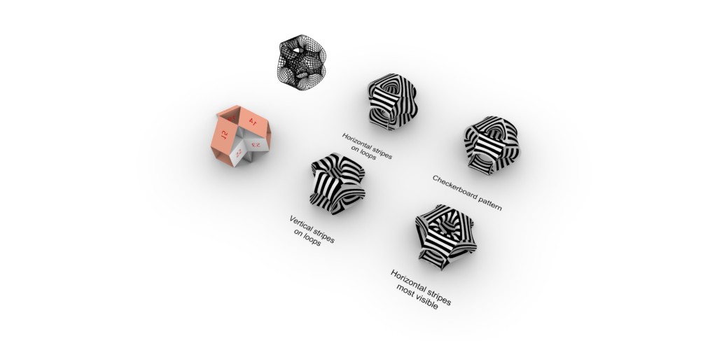
We created six coarse mesh geometries, of varying approach. Some were built predominantly from quads; others triangles. Building on earlier project development, we incorporated modular formations in most, and thought about how the surfaces might twist to meet themselves.
As we knew our goal for the project was to explore mesh topologies, we recognised that an ability to ‘look inside’ the shape gave good potential for creating continuous paths of stripes later in our study. For this reason, we built five of the six geometries in a way that it was possible to see the back side of some of the faces.
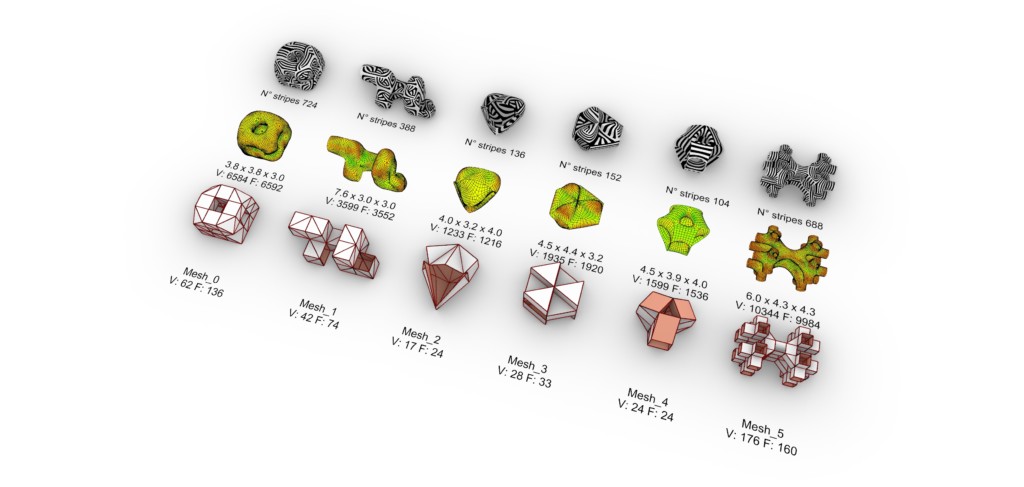
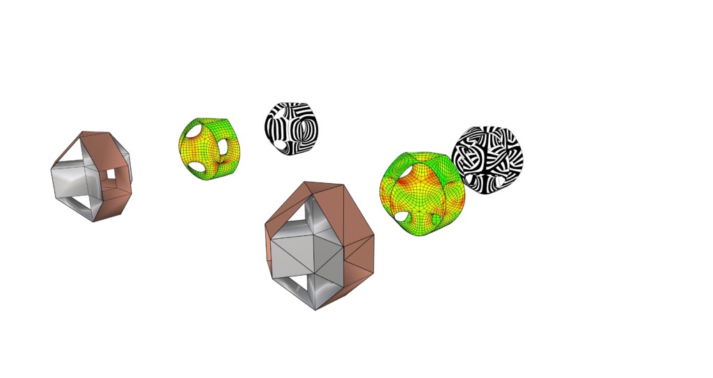
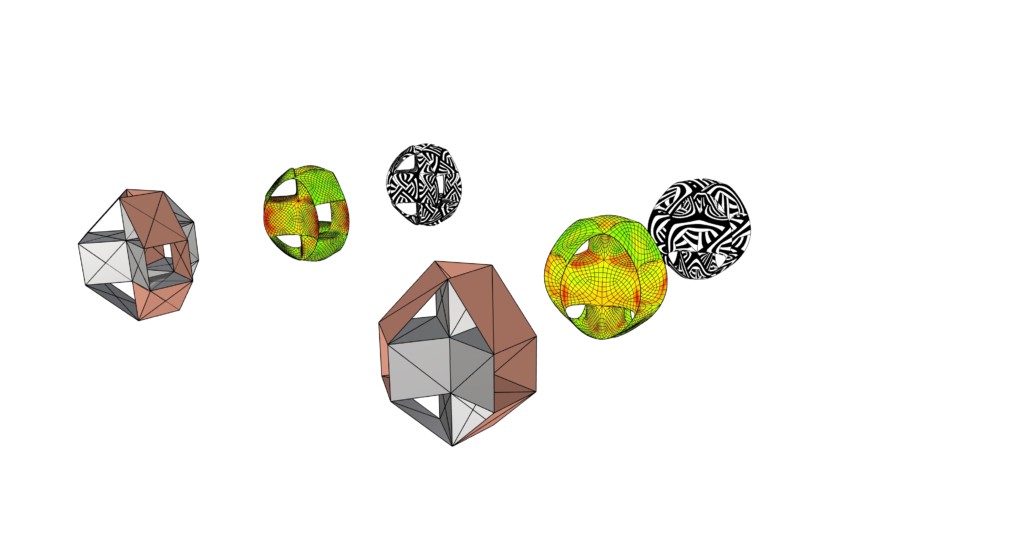
Six initial coarse mesh geometries (bottom line), with smoothing and curvature colouring (middle line), and stripes applied (top line)
To be better able to evaluate the coarse mesh geometries, we also created a smoothed mesh with curvature colouring: green represented low curvature, yellow medium, and red high curvature. Although many factors affect the force on a structure, including load distribution and where the structure touches the ground, we used this curvature colouring as a guide for where we might reasonably expect more or less efficiency of the structure to transmit local forces.
Finally, each of the coarse meshes were visualised with stripes to give an indication of the possibilities of shifting the mesh faces later in the study.
Selecting a geometry
Of the six geometries, the ‘inside-to-outside’ looping form that we desired for mesh exploration was best found in Mesh_0, Mesh_4 and Mesh_5. Of these, Mesh_4 was preferred as it was not too complex, with a relatively low number of vertices and f
hat we recognised could feasibly have multiple orientations when made as a pavilion, which gave more creative possibilities, and the curvature colouring of the smoothed mesh was mostly green, indicating it might have greater structural efficiency at distributing local forces when built. For these reasons, Mesh_4 was selected as the geometry with which we would progress.
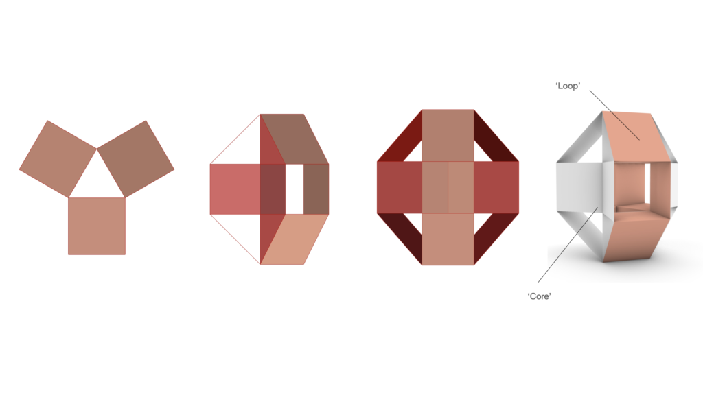
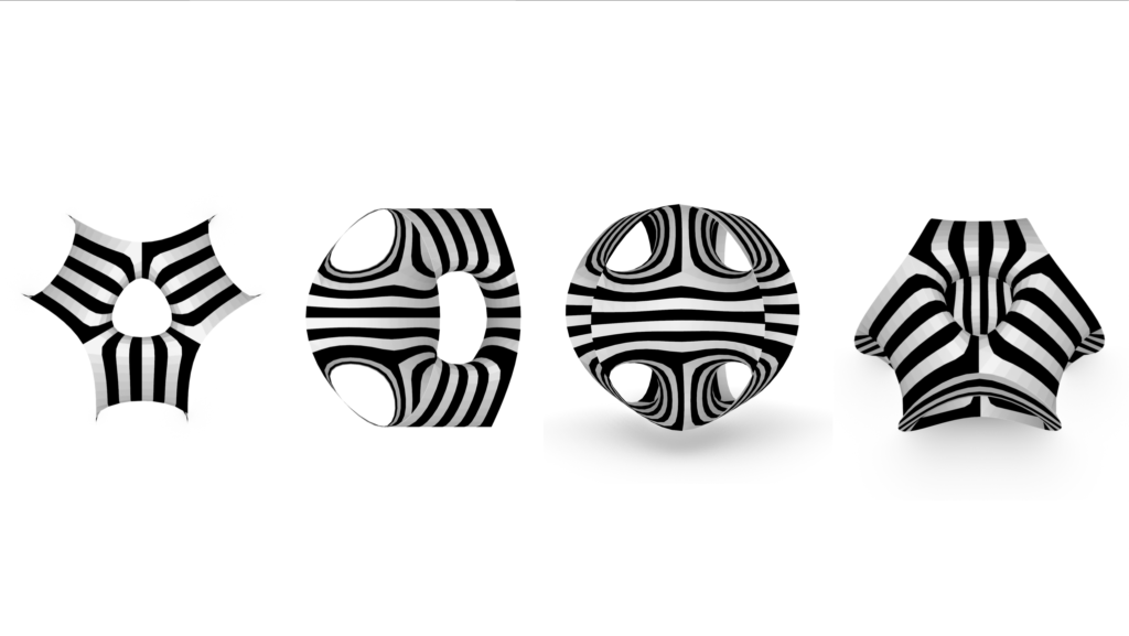
Mesh_4, from left: top, right, front, and angled perspective views of the selected coarse mesh. ‘Loop’ and ‘core’ are given as reference terms for areas of the geometry referred to in this write up.
Smoothing and relaxation exploration
Weaverbird’s Catmull-Clark subdivision was applied to our chosen geometry with varying combinations of parameters: subdivisions per face ranging from one to three, and with the shape’s naked edges fixed, smoothed, or with its corners fixed.
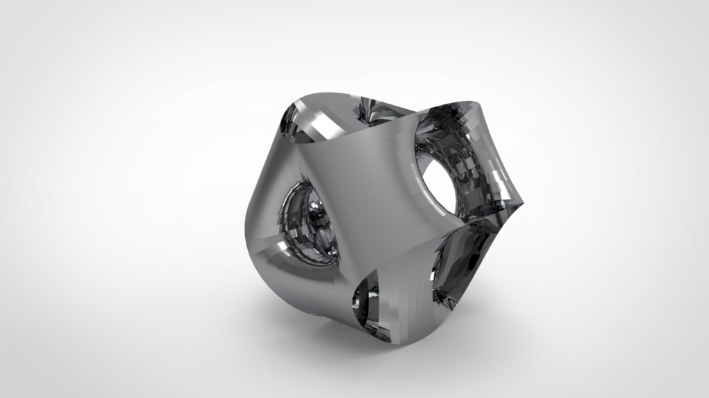
Our preferred mesh form had three subdivisions per face, and naked edges smoothed. We chose this as it seemed the most balanced volume, with an appearance closest to a sphere. In this form, the edges of the loops became like burst open splits in the surface of the ‘sphere’, allowing views into different layers of inner chambers of the shape: through these openings to the core, and through the tube openings to the centre. We felt this would create intrigue and an experiential aspect for people visiting the final pavilion.
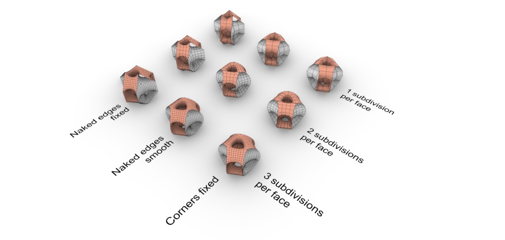
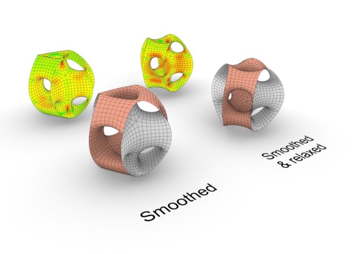
Smoothed meshes created with Weaverbird’s Catmull-Clark Subdivision and varying parameters
These mesh variations were then relaxed with the Zombie solver in Grasshopper. We had assumed that relaxation would increase the smoothed appearance, but were surprised to find that on every one of the smoothed models, it had the opposite effect: peaks appeared at the top and bottom of the geometry, increasing curvature and reducing the smoothness of the mesh. This took the shape away from the aesthetic appearance that we wanted, and, from the increased curvature, we hypothesised that the shapes would be less structurally efficient at distributing local loads.
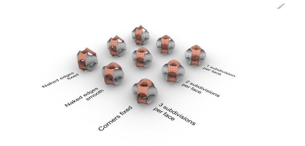
Smoothed & relaxed meshes. Smoothing as in previous image; relaxation via Zombie solver with threshold 0.00001, tolerance 0.0001, edge lengths of factor 0.7 and strength 5, and naked boundary edges as anchor points (783 points).
We realised this effect was specific to this geometry: the three loops relax symmetrically outwards from the central triangular tube, but this cannot move. From these modelling results we decided to progress with only smoothing of the mesh, and no relaxation.
Smoothing via Weaverbird’s Catmull-Clark Subdivision with 3 subdivisions per face (L=3), naked edges smooth (S=1). Relaxation via Zombie solver, with threshold 0.00001, tolerance 0.0001, edge lengths of factor 0.7 and strength 5, and with naked boundary edges as anchor points (783 points)
Mesh topologies
We then experimented with subdividing the faces of coarse Mesh_4 into different numbers of isosceles and scalene triangle faces, and checking the effect on the curvature and stripes of the resulting mesh.
Subdivisions A (left) and B (right). Each also display their coloured curvature model and stripes effect of the subdivided mesh
Subdivision A shows the effect from a mesh with all quad faces, as first modelled. Subdivision B divided all the quad faces into two triangles: rectangular faces became scalene triangles, and square faces became isosceles triangles. Subdivision C divided all the quad faces into four triangles. These two subdivisions were explorations to see the effect of the stripes on the core of the geometry. From the results we then moved to intentionally combine the effects to create Subdivision D. Here, all quad faces were divided into two triangles, with the exception of the quad faces that adjoined four others. These faces were divided into four triangles, as it created a striping system that could ‘collect’ the incoming stripes from the four adjacent faces, forming a pleasing and continuous topography.
Subdivided meshes C (left) and D (right). Each also display their coloured curvature model and stripes effect of the subdivided mesh
From these explorations, we observed that stripes resulting from triangular mesh faces could be particularly suited to geometries where three or four faces met at an outwardly protruding corner, as the stripes would create topographies that appeared to wrap around the smoothed point. However, our chosen geometry had no outward corners. Instead, its prominent junctures between faces were edges, where two faces met along a vertex. This junction was better suited by the stripes resulting from quad mesh faces, as they were able to ‘flow’ from one to the other without interrupting the vertex. We therefore decided to continue with a quad face mesh.
Striping exploration
We took the selected smoothed version of coarse Mesh_4, and applied a variety of striping methods. Due to the looping geometry, warp and weft would have had a robust form if a flexible material, such as plastic, had been used (see image). However, as our pavilion was to be made of aluminum, we decided to move forward with the stripes method.
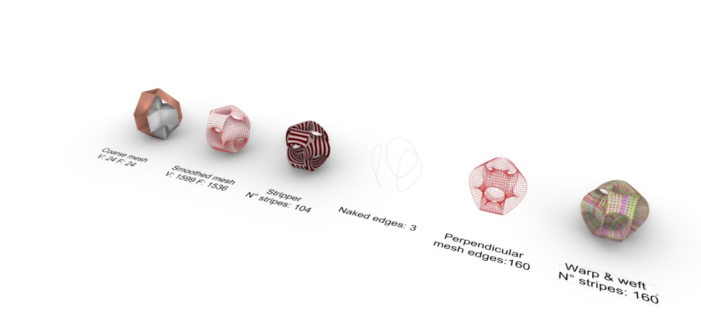
Various striping methods applied to the smoothed mesh
Quad face stripe topologies
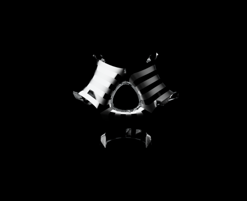
By shifting the faces within the smoothed quad face Mesh_4, we were able to produce some pleasing mesh topologies. In exploration 1 (see image), we shifted faces on the loops so all were horizontal, then followed these through to have continuous flows of stripes around the openings. In exploration 2, we took a similar approach, but with the loop striping vertical. Exploration 3 tried to see if it was possible to have a checkerboard pattern across the whole geometry – that is, the stripes on each quad face are perpendicular to the stripes on the adjacent quad faces. In conclusion, it was not – there was always one face in which the stripes flowed in parallel and interrupted the pattern. Exploration 4 took into account a visitor’s perspective, and sought to have as many of the stripes that would be visible at one time flowing in the same direction – in this case, horizontally across the loops and the core. the consequence of this was some ‘clashing’ or perpendicularly aligned stripes in other areas.
Quad face meshes with shifted topologies
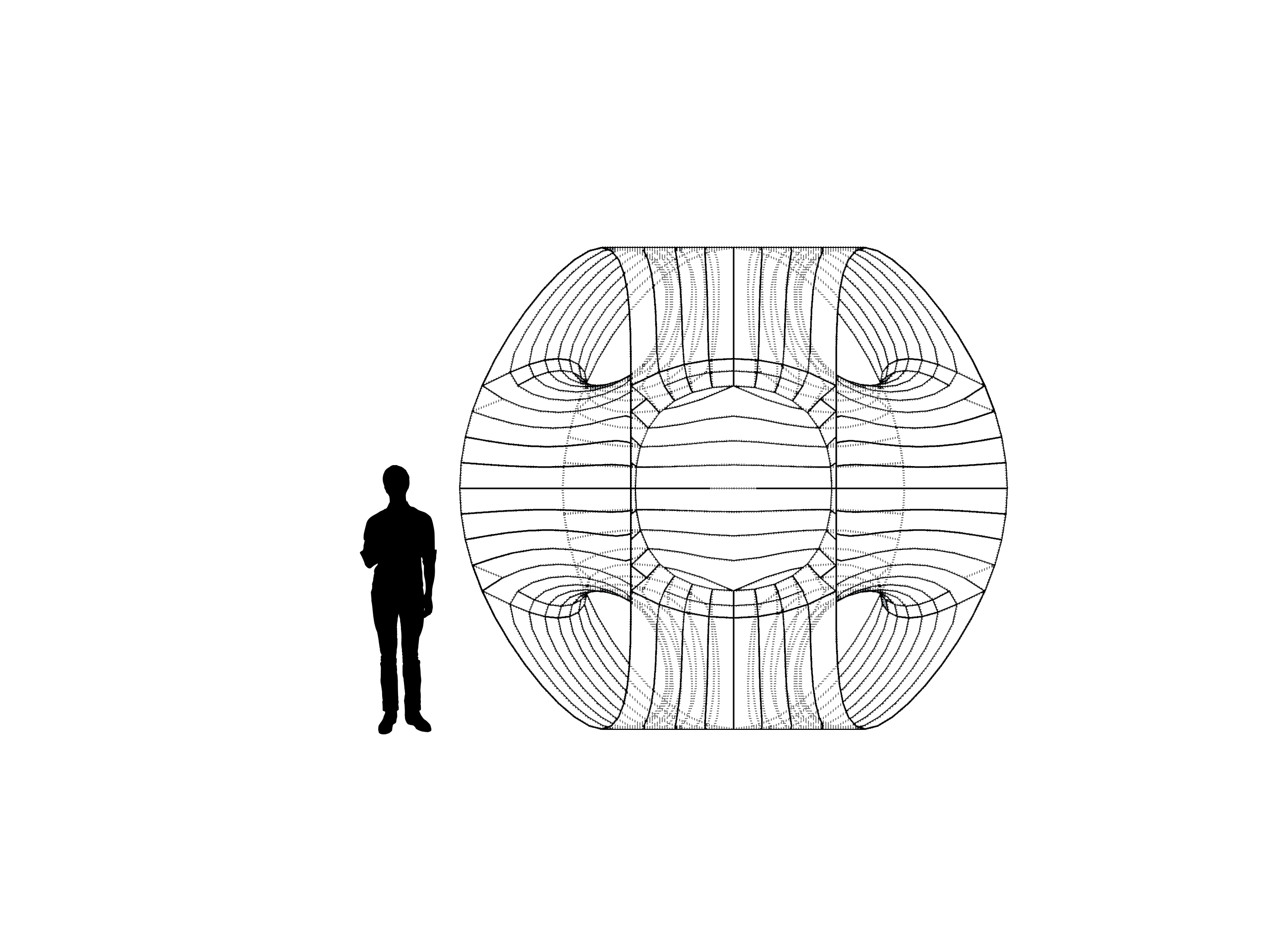
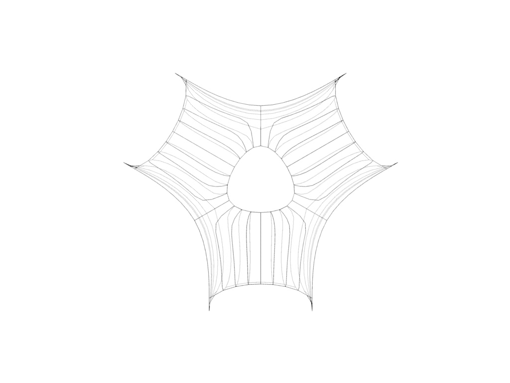
For our final form, we selected the mesh topology with stripes moving vertically down the loops, into the openings, and swirling out to wrap the core horizontally. We found this to be the stripe topology with the best continuity from a human perspective, if the pavilion were to be built at a size of 4.5 x 3.9 x 4.0m, and that this gave the structure an appearance of swooping fluidity that was absorbing and hypnotic.
The final striped mesh topology, from left: top, right, perspective and angled top views
Strip planarisation and nesting
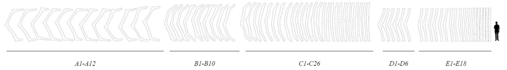
We then unrolled our chosen striped mesh topology, and distributed these forms on a plane. We had our structure divided into 72 pieces, 3.1-3.6 m long, and designed to be manufactured in aluminum metal sheet before a final assembly.
We ordered the pieces by length, and labelled them in groups.
Considering the density of our material (aluminum 1050), we managed to get the surface, volume and weight of each geometry.
The total weight of all the pieces will be around 142 kg, but these pieces will be obtained by laser cutting their shapes out of bigger sheets of aluminum. To optimise the amount of material needed to fabricate them, we need to place all the geometries in the minimum surface area. The Open Nest function in Grasshopper, will give us a fair solution by locating the pieces on nine boards (5.16 x 3.34 m) with the maximum dimension of the longest strip, filling the remaining gaps with the smaller pieces that fit better in the initial shape.
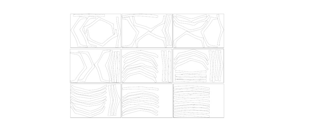
On this case we used 43% of the original surface to get all the pieces. Leftover material in the sheets will be used for manufacturing the joint pieces.
These joints will be 10 cm wide hexagonal shapes, having similar surface benefits as circles and getting the maximum material thanks to its paving function.
Material and process
As commented before, all the pieces and joints are made in aluminum 1050T lasercut pieces, as they are made of 0.8 mm thick soft metalsheets.
For the structure’s assembly, all the pieces will be riveted with a pneumatic gun and 4 mm rivets.
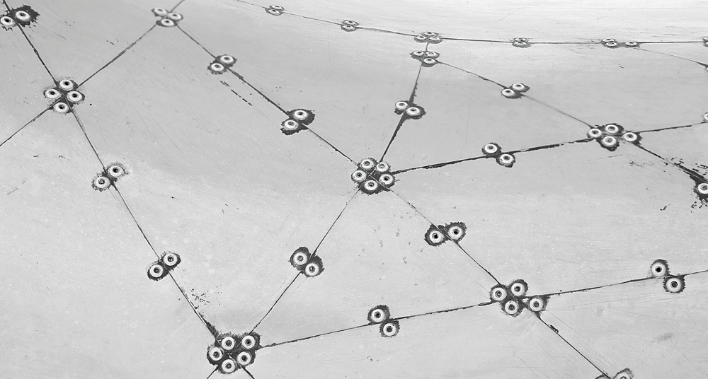
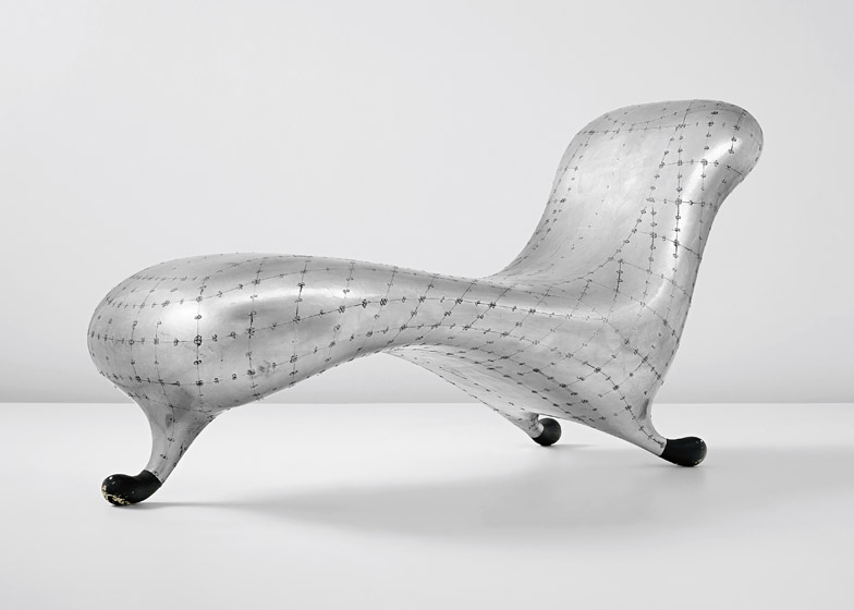
Rivets on Marc Newson’s Lockheed Lounge design
Connection, system, scale and context
To get a better joinery system, flaps should be studied along every other strip to get an additional joint area between the pieces. Otherwise, the same hexa joint could be used even to joint the sheetmetal onto an inner wooden substructure.
Reinforcing the structures with framings, we can create a static anchored solution that, increasing the materials thickness and fixing it to the ground, could turn the piece into an interactive moving structure, on which the audience could go through and connect different spaces.
HUMBUG is a project of IaaC, Institute for Advanced Architecture of Catalonia developed at Master in Robotics and Advanced Construction (M.R.A.C.) in 2021 by,
Students: Grace Boyle, Alberto Martínez López, Abanoub Nagy Abdou Mikhail
Faculty: Andrea Graziano, Eugenio Bettuchi