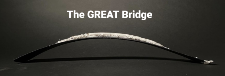
A challenge to 3D print a lightweight bridge to bear load over a span of 50cm from a choice of two geometrical options:
- A modular lattice, in which forces are distributed through the vertices of the spatial frame.
- A more conventional looking span bridge in solid PLA, in which stress lines were identified through Karamba analysis, and then printed over to reinforce the structure.
In both, the challenge was to balance using the least amount of material with the greatest strength, and to reiterate the design for optimal material deposition for performance.
Our team chose to proceed with option 2. For the initial shape we began with catenary curves, as their compressive strength is well known. We juxtaposed three catenary curves along a line, inverting each one in relation to the last, and joined them via a fourth, perpendicular catenary curve. We then played with different width variations across the structure to find the minimum amount of print material that might be used.
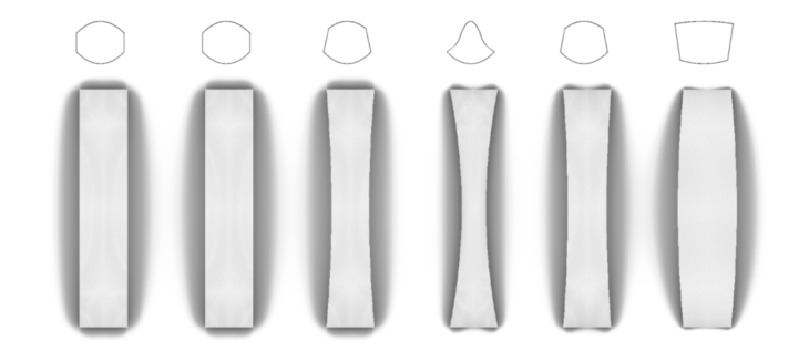
Initial bridge designs, shown with front elevation to illustrate variations in width.
Print orientation
Given the arch shape of the bridge, printing it on the XY plane would have required supports; these supports would have increased the amount of material used and the time taken for printing. Due to the concave orientation of the terminal caternary curves of the bridge, there would also have only been a single point of contact between the forming bridge and the print bed, which would have caused stability problems in the printing process. We therefore decided to print in the z axis. This allowed it to be printed without supports, using only a raft bed; it also allowed the base catenary curve to make full contact with the raft bed, which was provided a stable base for the forming shape.
A compromise of printing on the z axis was that the print lines would have to be transversal relative to the length of the bridge, whereas the optimal orientation, in terms of the bridge being able to bear load, would be to have them printing longitudinally. There were also potential stability issues for the forming bridge as it would be standing over 50cm on a single base curve, but these were both disadvantages that we judged to be worth the compromise.
Raft design
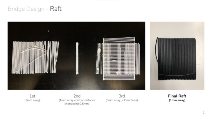
We then designed a raft on which the printing bridge would be formed. The raft would be printed first, followed immediately by the bridge. Its purpose was to provide a base for the bridge with a stronger join than if the bridge was printed directly on the MDF base: the greater surface area of the raft would create an overall adhesion to the MDF base, and the melted printing plastic of the bridge would adhere to the plastic of the raft.
Through this adhesion and its extension in the XY direction, the raft would also provide some additional stability for the bridge as it built up along the z axis.
Our first raft design was a series of parallel lines 3mm c/c. This came unstuck from the raft within the first few print lines of the bridge. To increase its rigidity and adhesion, our subsequent raft design was a series of perpendicular lines. The final raft design successfully incorporated perpendicular lines in a 1mm c/c array.
Stress lines
There were three stages to the print process: a) printing the raft, b) printing the bridge, and c) printing stress lines on top of the bridge for reinforcement.
To identify where these stress lines should be printed on the bridge, we analysed the structure in Karamba 3D. We then eliminated the shorter lines through data management in grasshopper, and selected 9 of the longest lines that in combination covered the most diverse area.
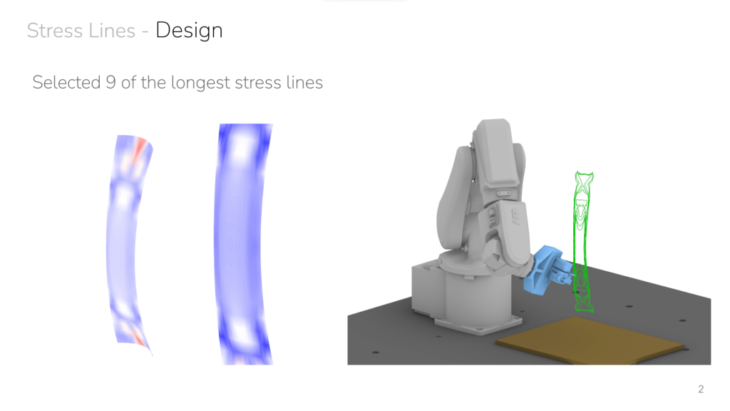
Printing the bridge was fairly straightforward in terms of kinematics as it only required the robot arm to ascend in the z direction. However, printing the stress lines onto the bridge required us to navigate many issues of collision, both of the robot arm to the table, and of the robot arm to the printed bridge.
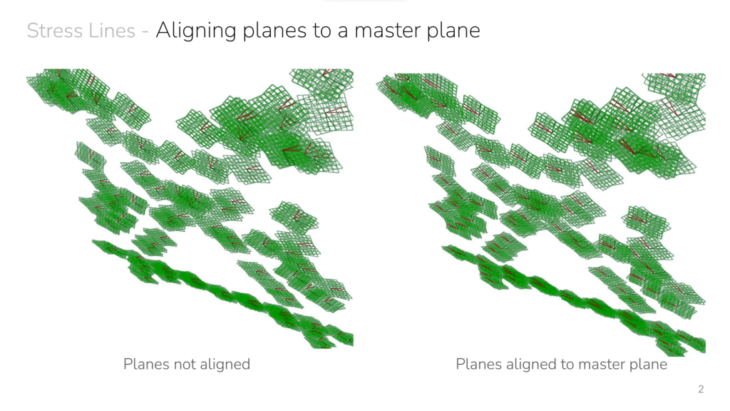
- Aligning xy planes to a master plane – the stress lines were read by the robot as a series of points, each of which has an xy plane, the normal of which determines the angle of approach when printing. Initially, these angles were different for each point, which would have occasionally cause the robot arm to collide with the bridge, and also wasted time in changing its oriention between each point / plane. We selected a master plane from the middle of the bridge and aligned the normal of all other planes to the normal of this one, to unify the angle of approach of the robot arm when printing the stress lines.
- Unifying the z orientation of the planes – it was necessary to flip some planes to make all the z axes point in the same direction, stopping collisions of the robot arm with the printed bridge (as well as saving time).
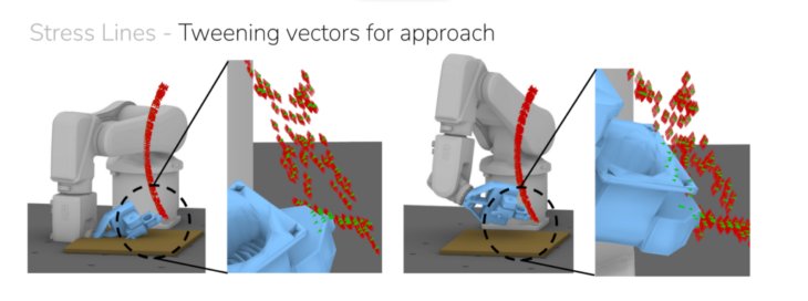
- Tweening vectors for approach – many of the angles of approach of the lower planes would have caused the robot arm to collide with the table. To avoid this, we tweened the normals of all planes with the global z axis.
Initially, our code for printing the nine stress lines was based on a continuous printing process, as described by the following pseudocode:
- Approach plane
- First plane of first stress line. Extruder on, air on, extrusion wait time
- Print all 9 stress lines
- Last plane of last stress line. Extruder off, air off
- De-approach plane
However, we soon learned that karamba had provided stress lines with starting points at very different points to each other, which was causing the robot arm to collide with the bridge when travelling directly from the end point of one stress line to the start point of another one. We therefore finalised code with the following logic:
- Approach plane
- First plane of a stress line. Extruder on, air on, extrusion wait time
- Print that stress line
- Last plane of that stress line. Extruder off, air off
- De-approach plane]
- Repeat for all 9 stress lines
We were able to do this via data management in grasshopper, without having to change the commands.
Failing not too fast
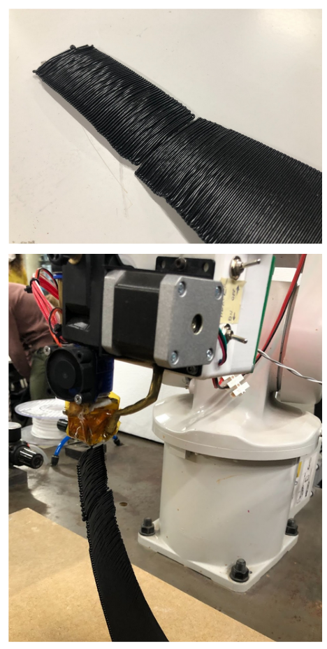
Geometry of bridge printed well at first – speed, contour height gave good tight results
Towards the middle of the bridge the geometry began to narrow, which gave less drying time for the thermoplastic between layers.
Added a fan, though the airflow caused some movement in the workpiece.
Movement was also caused by the path of the robot arm on top of a relatively flat lower geometry, which didn’t give enough support to the area being printed. The workpiece began to wobble and faults developed.
Conclusions:
– lower the printing speed to give fatter, stronger layers with more time to dry
– widen the bridge geometry at mid point
– make the whole bridge more curvy to provide greater support when printing, and strength in final piece
The GREAT Bridge is a project of IAAC, Institute for Advanced Architecture of Catalonia developed at Masters in Robotics and Advanced Construction, in 2021/2022
Students: Mit Patel, Grace Boyle, Alberto Martínez López and Abanoub Nagy
Faculty: Eduardo Chamorro Martin
Faculty Assistants: Marielena Papandreou