ABSTRACT
The following structural analysis and studies relate to the studio project: “Fynbos” which is designed to address Cape Town’s Water shortage, while creating a water landmark and reusing/ rewilding existing spaces. The choice of form is based on the water collecting capability and relationship to the un-used motorway which it is built on top of. The analysis looks at various design options in relations to sections, column options, arrangements and lattice designs to respond to various loads and local conditions.
MATERIALITY
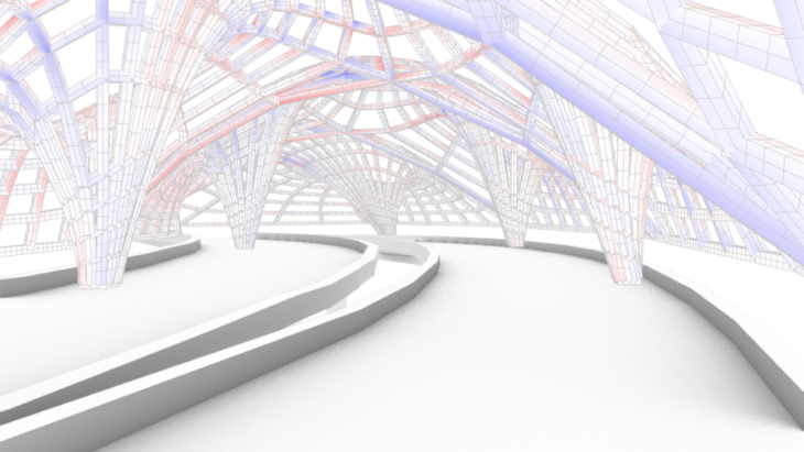
A light-weight timber lattice structure was decided for the project due to the necessity to have large spans, double curvature and transparency.
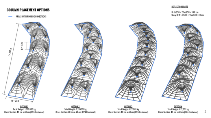
In regards to the materiality, we looked into suitable woods available for creating free form wooden structures. Currently in South Africa there are vast amounts of non-native trees which are very water-hungry and are responsible for using an equivalent of two to three months of Cape Town’s annual water consumption. In response South Africa have be chopping down 10s of thousands of trees around local reservoirs to increase the water supply.
From these non-native trees that have been strategically removed we decided to use the eucalyptus due to its abundance, large lumber sizes and good bending properties for free-form structures.
Invasive eucalyptus account for 16% of the 1,444 million cubic metres of water resources that South Africa loses every year due to invasive plants.
GRIDSHELL CASE STUDIES
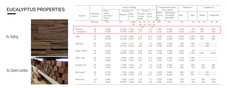
For our overall design we took inspiration from various free-form precedence which utilize wooden grid shells in their formation. In these examples, finger-jointed and laminated timber members were used to make an orthogonal grid which is dropped down to create the forms and then stabilized with either horizontal or vertical members like in the left example or solid panels as shown in the right.
Both structures perform similarly with the drops in the forms working in tension while the rises and peaks take the compression. Our structure follows suit though the undulating topography that is formed.
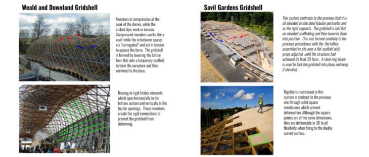
COLUMN PLACEMENT OPTIONS
OPTION 1: The middle dip in this cross section is a point a weakness as it acts like a hinge. However, since the density of columns and beams in this option is high, it performs just well or even better as the other options under dead and wind loading.
OPTION 2: This option is made up of two different cross sections, a double peaked unit and a symmetrically arched unit. The geometry of the arched unit is much stronger than the double peaked one.
OPTION 3: The cross section profile very closely approximates a catenary arch, making the structure very strong under vertical and lateral loading.
OPTION 4: The cross sections in this option performs better than the double peaks, but not as efficiently as the symmetrical arches due to them being skewed.
DEADLOAD COMPARISONS
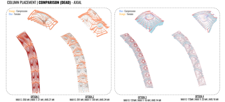
Two different versions of karamba were used. We realized that the older version outputs the opposite colors than the new version for axial forces. All options show the highest axial forces in the outer members of the single units were the elements are longest. Forces decrease the closer you get to the columns as the elements get smaller. The elements mainly all exhibit compression forces except for the radial rings that encompass the columns which are in tension to hold the column elements together. All of the options show a fairly uniform distribution of axial forces except option 2 which presents higher axial forces in the unit with a single column than the double column unit. This is due to arched cross section shape of the single unit being much more efficient than the double peaked section of the double unit. 
The bending moments are similar to the axial forces, showing highest moments in the longest elements. There is little moment in the columns as they act mostly axially. 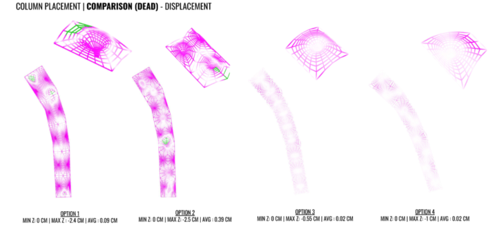
For all options we see the the average displacement of members is much lower than maximum displacement indicating that the structure sees local areas of deflection, just at the areas where the load is applied, as opposed to large areas of global deflection which would have indicated that our structure was not very stable.
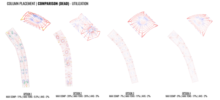
Under dead loading, option 2 was clearly the worst with the highest utilization values. This is because the loads preferred to transfer to the units where there was only one column across the width opposed to the arrangement with two columns, leading to the two column area to be under utilized in relation to the rest of the structure. Option 3 performed the best because the tributary area of loading for each column was the most uniform compared to the other options. Option 4 performed similarly to option 1 even though it had a much smaller mass and fewer columns. Option 4’s efficiency most likely comes from its shape. In section it approximates very closely to an arch, whereas a section through option 1 shows a less efficient double peaked arch shape.
WINDLOAD COMPARISONS
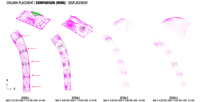
In terms of displacement, we saw the most displacement at the application site of the load. This makes sense as the load was applied as points for simplicity as opposed to distributed. Overall, there was very little twisting throughout the options due to the fact that all the edges of the roof structure were pinned. 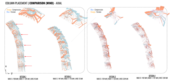
That the forces in options 1 and 2 are much more evenly distributed, resulting in lower maximum utilization values. 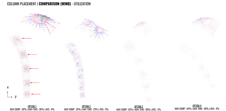
Utilization is much higher in options 3 and 4 than in 1 and 2. If we look at the next slide of axial forces we can see.

LATTICE COMPARISONS
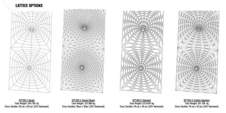
After investigating the column placement and form for water collection, focus was placed on how these forms would be constructed and what lattice would be used that suits both the architecture and structural necessities. A general force flow analysis was taken to understand best where a structure would work most efficiently to take loads. We then selected four lattice patterns suitable for our scheme and analyzed them under dead loading and wind loading from the long elevation.
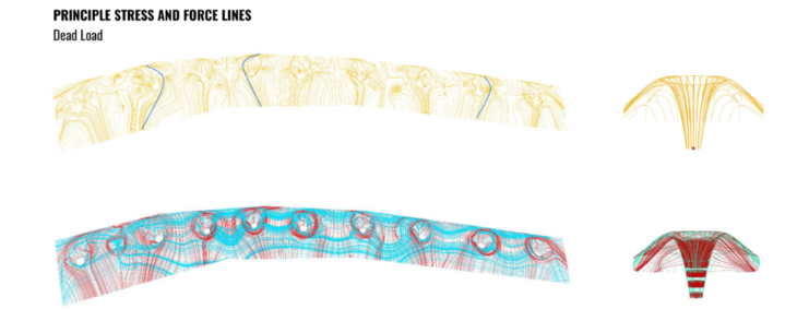
STRESS LINES
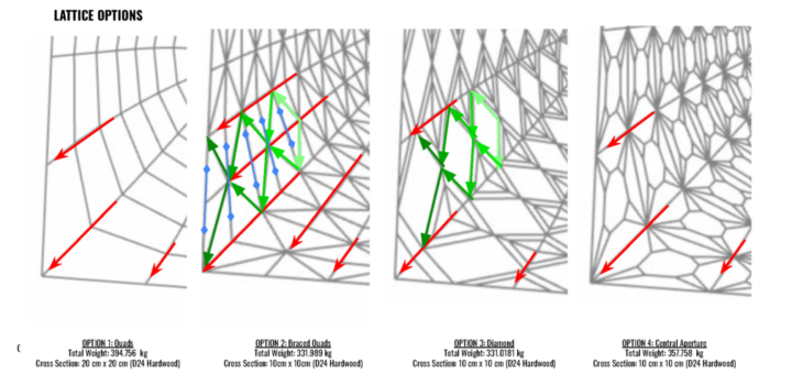
Prior to experimenting with various lattice types we ran principle stress and force line analysis in order to determine the most efficient structural orientation. For the dead load, principle stress lines ran orthogonally as shown here. The longest force lines run along the column and in the short section where there are openings in the form. Between the holes, the force lines become less dense as there are no breaks in the form and force flows in this area.
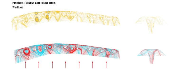
In contrast, when applying a wind load, the principle stress lines counteract these forces through a diagonal orientation. We tried to combine these results through various lattice combinations. The longest and most dense force lines can be seen between the peaks where the units join.
DEADLOAD COMPARISONS
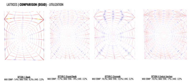
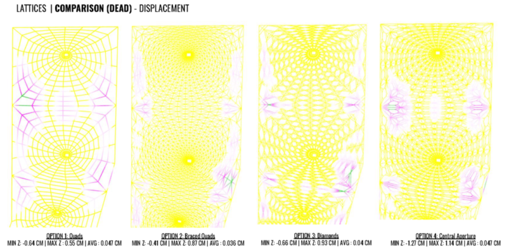
The displacements are very small and also similar in between the lattices options, but second option is a little better, in average. And the utilization is more balanced in option 2.
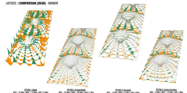
Each has it’s own manner of transferring the load, the option 2 is the most optimized one, considering it’s simple triangular pattern. Comparing the axial forces and moment for each pattern, it’s clear the area under more stress are the connection between each vault piece. 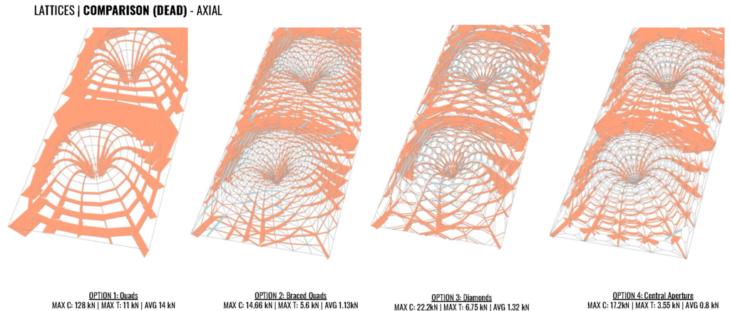
WINDLOAD COMPARISONS
We looked then looked all four options under wind loading along the long section where there is a prevailing wind and the structure will most be affected by the wind due to the exposed surface area. Given more time the wind loads would be analyzed from all directions, however the main wind direction still provides a good indication of what stability systems work and don’t.
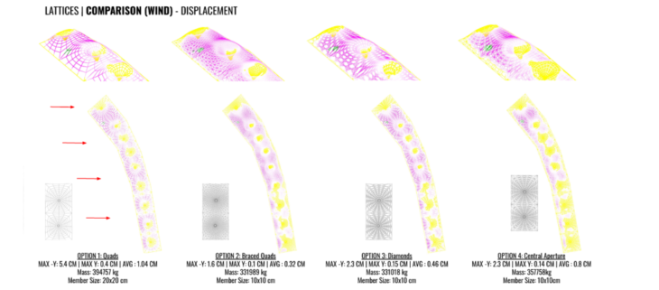
The structures most deform where the form twists against the wind and the surfaces fully exposed to the wind. Option 1 which has no bracing to provide stability again loading in the long section direction has most displacement, in contrast to the triangular bracing in option 2 which greatly helps resist the wind forces. These was also evident in the principle stress lines shown early with wind load applied to the shell.
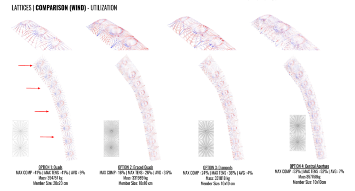
Utilization is much higher in option 4 where the forces are less evenly distributed between the apertures in contrast to option 2 where the peaks can be seen working in compression and the drops in tension as seen in typical gridshells. Option 1 has the fewest members and therefore the highest utilization, however there is a lot of deflection against the wind load.
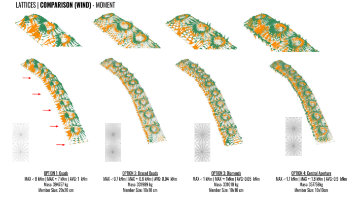
The bending moments are highest moments on the longest elements directly exposed to the wind and the upper ridges while in contrast the columns are sheltered from the wind and there is little moments in these areas. In Option 4 where the lattice forms a circular opening and has no triangulation, there can be seen greatly bending. The options with more triangulation perform generally much better over the surface as the forces are distributed diagonally to the corner points. 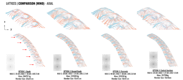
For options 1 and 2, compression is shown in blue and tension in orange. The overall structure and closeup on the end units in all the options show that highest axial forces are applied where the units join and members become most longest with spread out grids. The more dense elements in the centre and closer to the support points take the least forces. The peaks and troughs can be seem working in compression and tension.
CONCLUSION
To conclude from the analysis, an evenly spaced column arrangement with its arched shaped provides the lowest total weight and deflection under dead loading and wind loading. In relation to the lattices, option 2 and 4 perform best in relation to least displacement and smallest bending moments, however taking into consideration the mass and number of members, option 2 would be most suitable to apply to the form with it performance again both wind and dead load.
Balancing the architecture of the lattice to allow for a large enough opening, while maintaining the cross bracing is one of importance. Although a triangulated lattice works well through the analysis it would obstruct some of the architecture in the scheme. Further analysis should be taken to add the bracing in key areas such as where wind load and water load is strongest and potentially increase the member sizes where there is highest utilization.
CREDITS
Fynbos: Structural Analysis is a project of IAAC, Institute for Advanced Architecture of Catalonia developed at Master in Advanced Computation for Architecture & Design in 2020/21 by:
Students: Barbara Villanova, Bruno Martorelli, Michal Gryko, Sophie Moore
Lead faculty: Manja van de Worp
Faculty assistant: Matthew Gabe