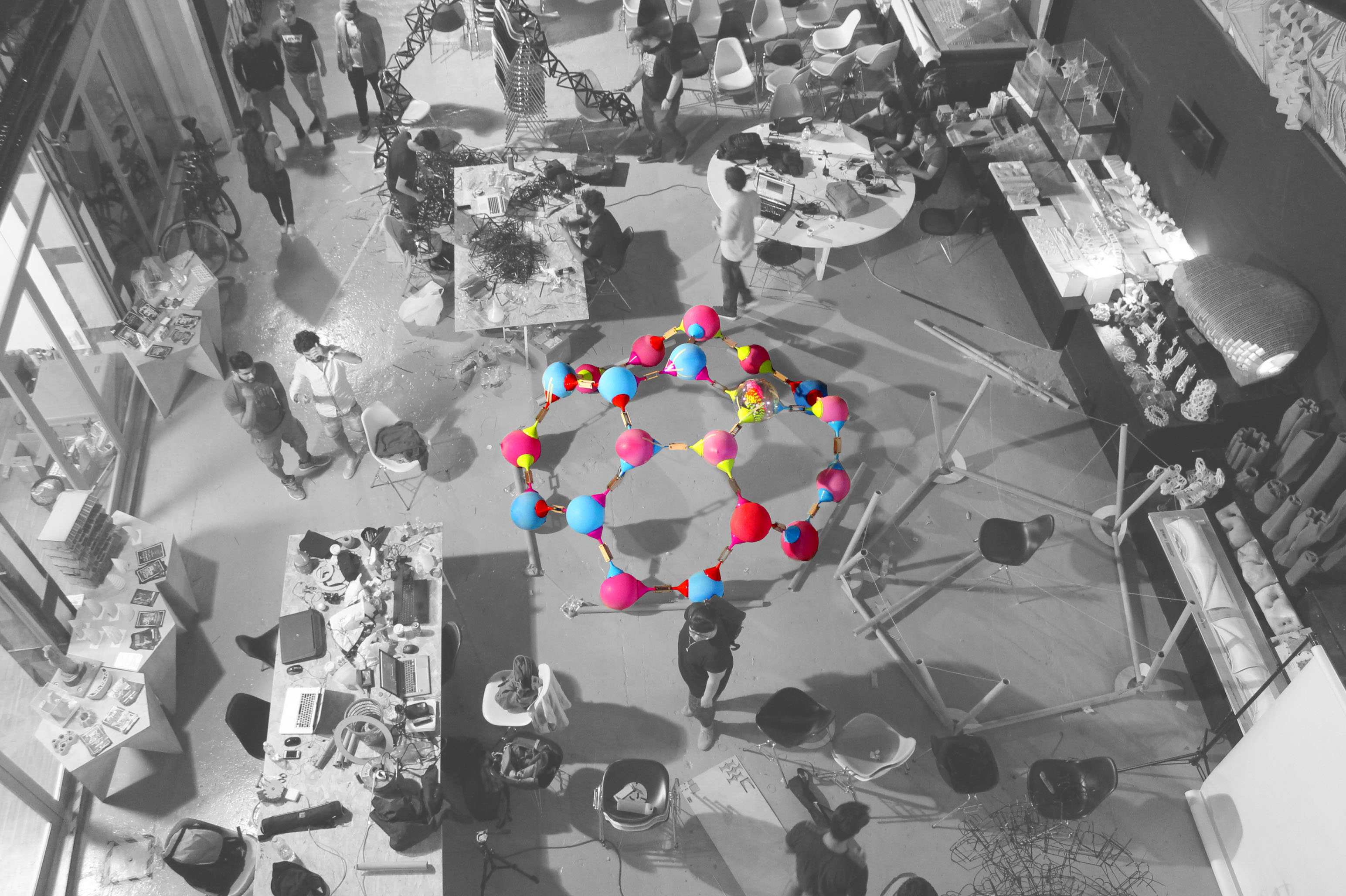
[FUN]nel is an experimental structure based on the idea of a future where mass produced non-biodegradable objects from the past are repurposed as building materials for the masses. Out found material for the project was the funnel.
The structure was formed of three primary components – funnels, balloons and tubes.
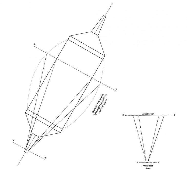
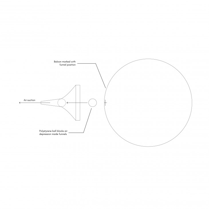
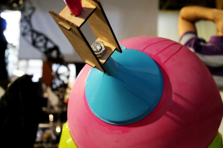
The funnels, owing to their tapered conical geometry provided a means of attaching larger elements to smaller and more detailed joints – it allowed joining large elements in a precise fashion. This was a major driving force of the project which led to various experiments. The compressive capabilities were great, especially when paired up, as was the possibility of passing elements like strings through them to keep them together. What was perhaps the most exciting was the capability to use suction joints, where a Styrofoam ball can be used as an element that maintains pressure that can attach to elements by locking onto the neck of a funnel.
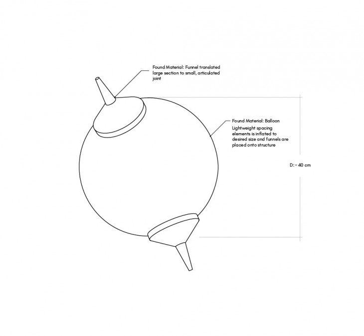
The preliminary explorations of the funnel were focused on small aggregations of dense tetrahedron hyper modules. However, the density of the hyper module created a cost-prohibitive structure. As a result, we explored the idea of adding spacing elements between the two funnels, creating larger geometries.
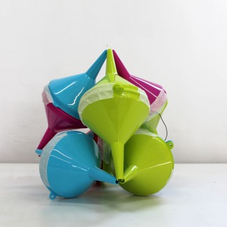
First iteration dense hyper module
Physical prototype
Spacing logic
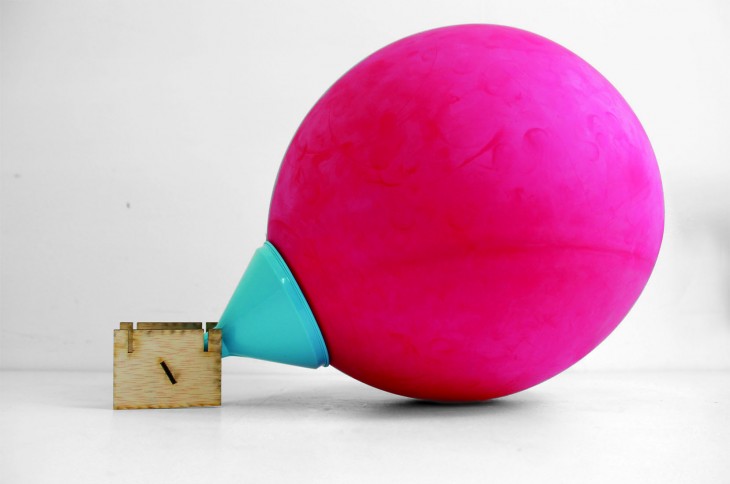
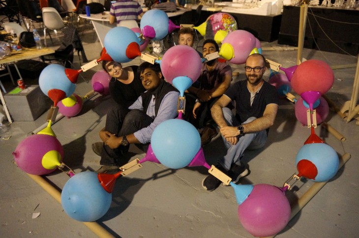
Spacing iteration with inflatable balloon
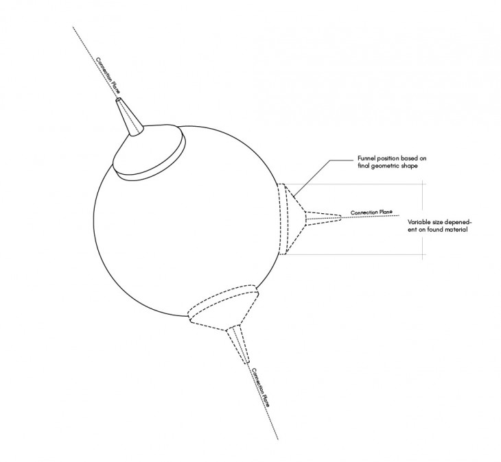
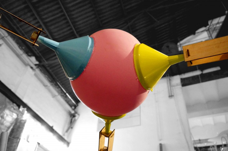
Balloons were the primary joints that by nature of being spherical could allow various attachments on its surface, thus being able to achieve a multitude of surface geometries, requiring attachments at different angles. Their elasticity gives scope for manipulation, and absorbing minor errors in the joinery. This is the element that the funnels are stuck onto through suction.
Funnel placement
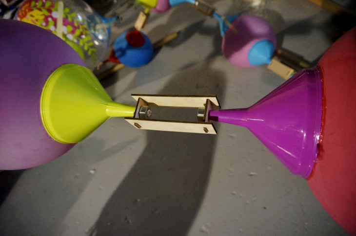
Connection Joint
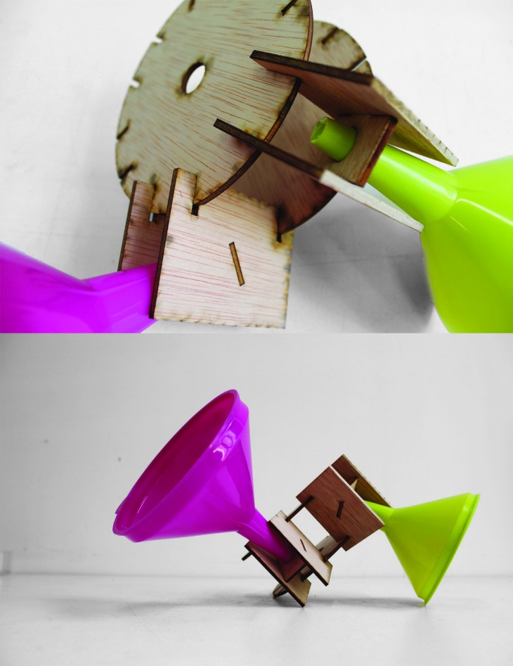
Connection between the modules were needed. To reduce complexity, a planar wooden joint was fabricated. The wooden joints were used to hold the funnels in place in the x-y plane, while the balloon was used to control the z-axis placement.
Planar parametric connection joints
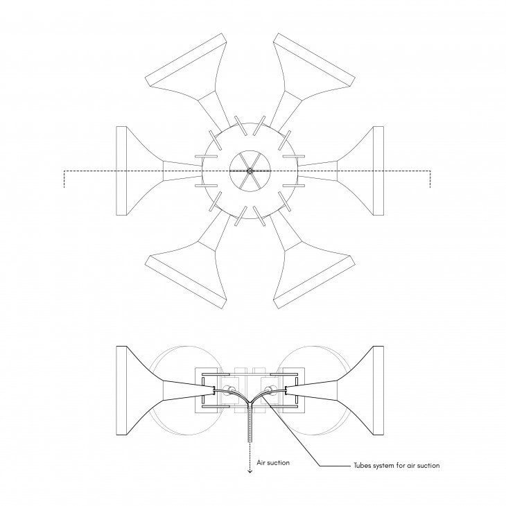
Evolution of the Joint
To increase efficiency, we imagine a central node upon which the user could suction all funnels at one time.
Final Design
Tubes, which could be recycled pipes, were used to provide a substructure that could potentially make the space more accessible and inhabitable.The tubes angle outwards and branch into the dome element.
All put together, the structure would enclose around 4 square meters of space, and stand at a height of 2 meters.
What results is a structure that is reminiscent of molecular attachment models that is capable of being formed into a variety of shapes. To minimize the price, also a very important decision making parameter, we decided to use a dome structure, that maximizes the volume for surface area. With a limitation of 20 balloons and 50 funnels, the top of an icosahedral dome defined the geometry.
IAAC, Lightweight Structures.
This is a project of IaaC, Institute for Advanced Architecture of Catalonia developed at Master in Advanced Architecture, MAA01 in 2016 by: