SCHEDULING
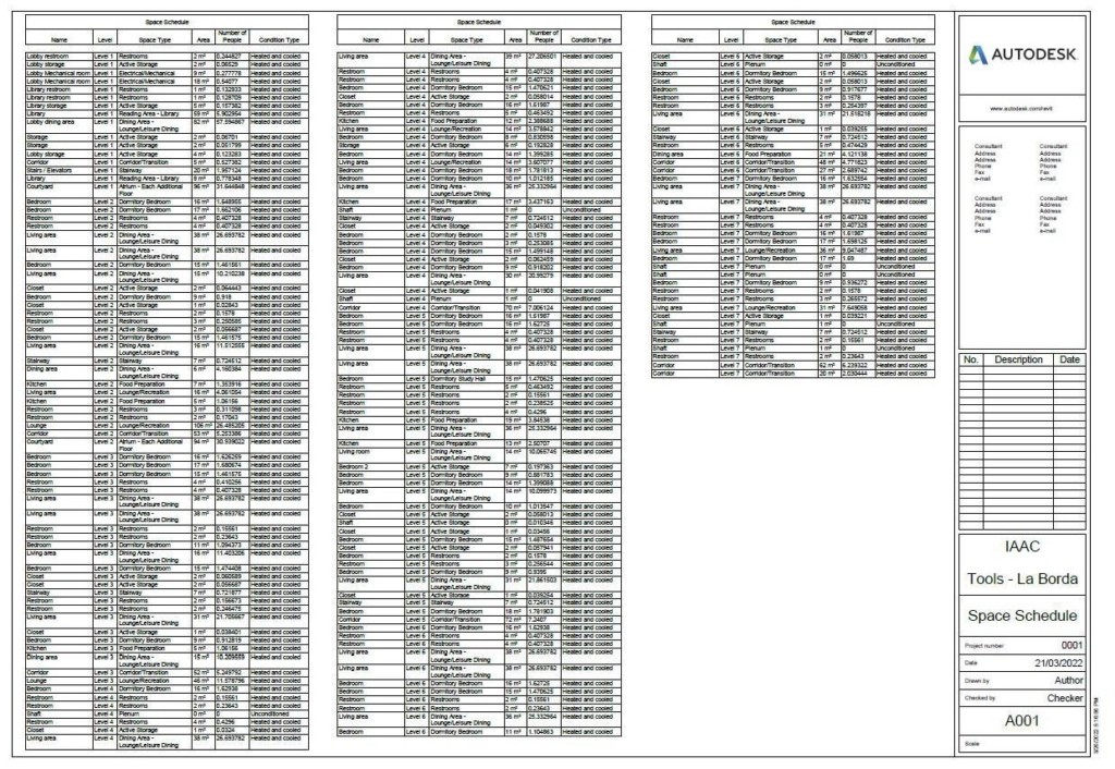
Space Schedule
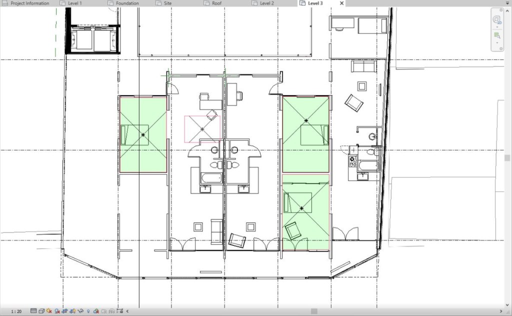
Scheduling and schedule creation is one of the last steps in the collective exercise. The fist schedule created was the space schedule, this schedule also needed for the energy analysis so this was the first coordination effort within the process. The spaces where divided by levels and categorized by function or “Space type” to understand the cooling/heating requirements. Only spaces with useful square meters where considered therefore the shafts reflecting 0 m2 where ignored for this specific schedule.
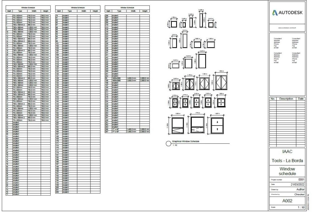
Windows & Doors Schedule
For the windows schedules a graphical schedule was included to visually aid the results. Only previously defined windows families where able to be included in the graphical representation. Custom created elements, like shutters, were not able to be sorted or included in the graphical representation.
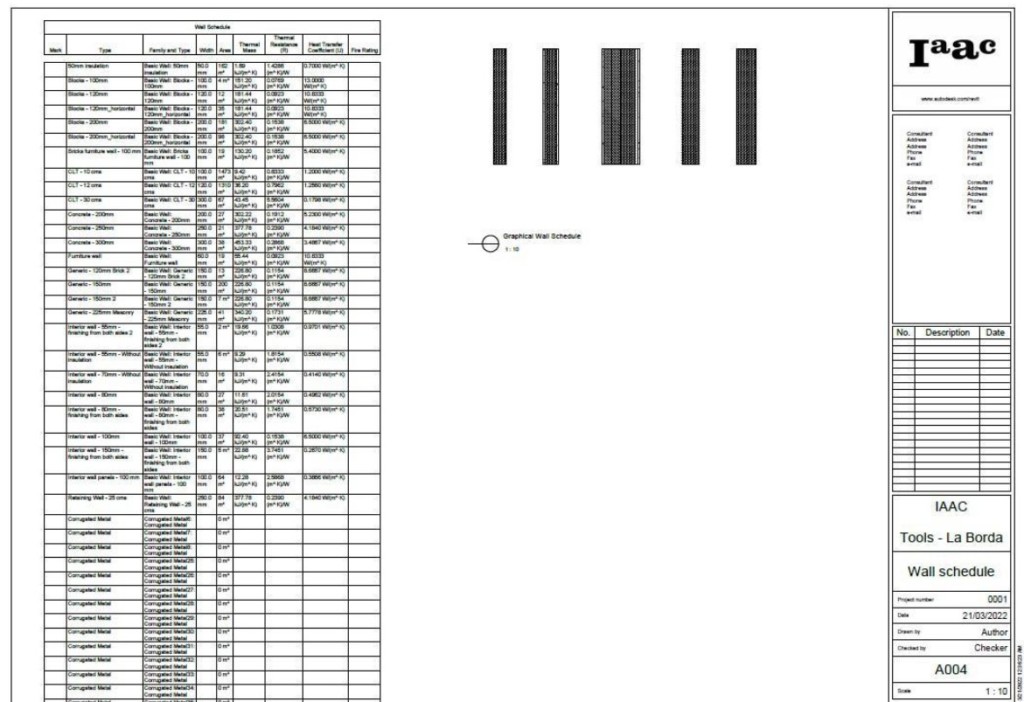
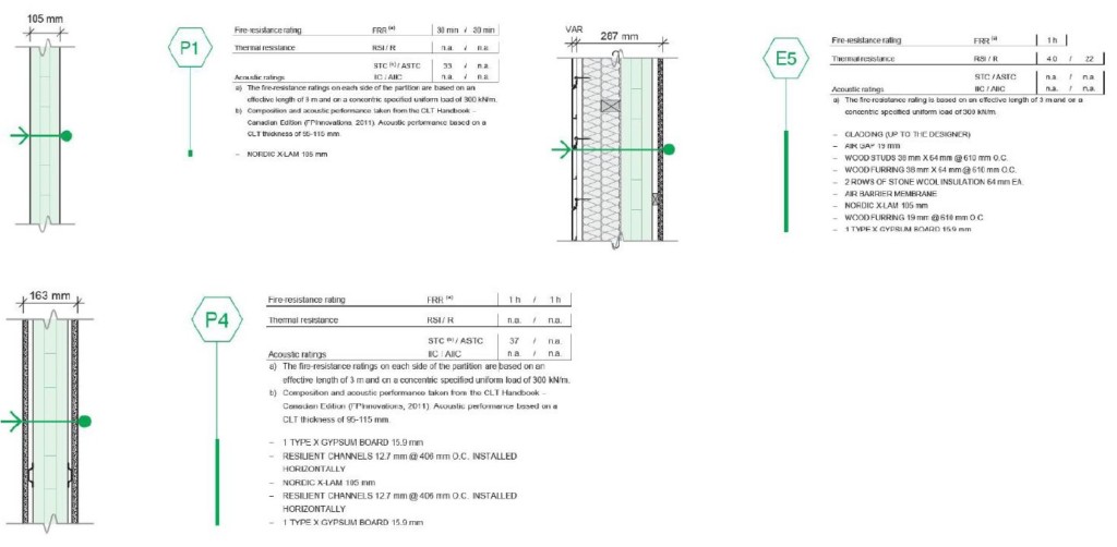
Wall Schedules
Similar to the window schedule, the wall schedule reflected several iterations of the same wall and thus generated a very long schedule.
The multiple families created to reflect the different wall compositions, used in the project were not able to be included in the graphical representation.
The length of the schedule was also a challenge since the break line was not present and sorting was not possible.
Wall Assemblies
The wall schedule was also a coordination effort due to the fact that the wall compositions had to be kept within the already stablished and created wall thickness.
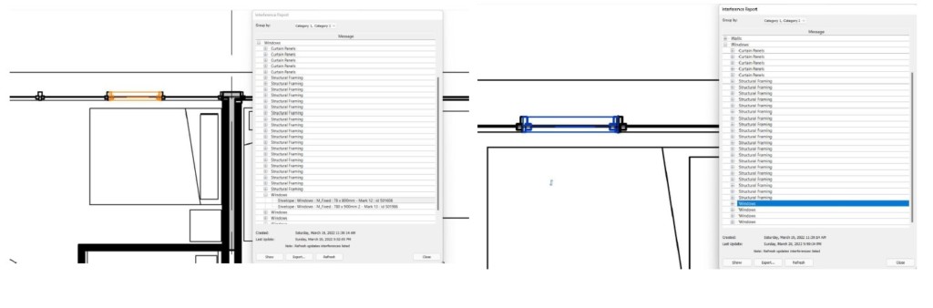
Clash detection
After the clash detection report was generated, we identified a door that was creating an issue according to its positioning. The issue was fixed by deleting the element and re-inserting the same door type in the same position.
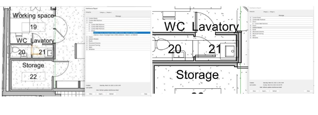
Another issue fixed was a window that was creating interference due to its overlapping geometry with the adjacent windows on each side. The issue was fixed by adjusting the window sizing and reducing it.
ENERGY ANALYSES AND SOLAR STUDIES
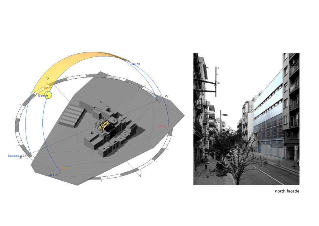
Solar Studies
After having the exact location of the project selected on Revit, we initially observed the sun path and exported images from the summer solstice and winter solstice. By providing accurate location and modeling the surrounding buildings, it was possible to get relying results.

Energy Analyzes

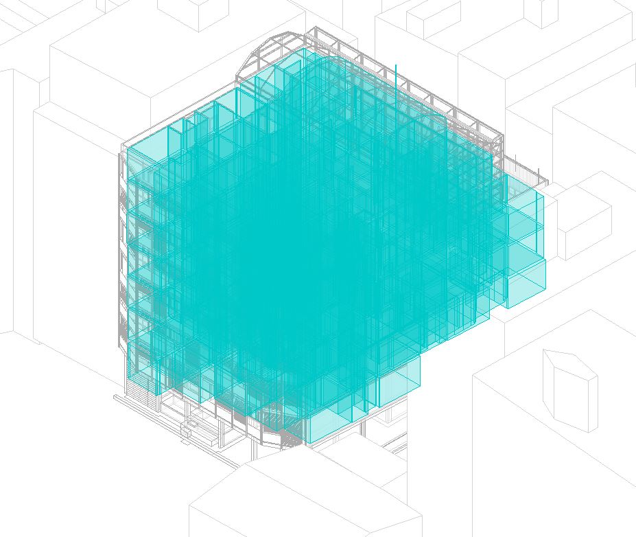
The first task to create a detailed energy model was to create spaces within the revit model. Due to linked models and none room-bounding areas, most spaces were created manually. After creating the spaces on the plan views, they were checked and modified in different section views.
Once all the spaces were created, we generated an energy model and received the results from Insight.
The first results were much above Ashrae 90.1 and energy consumption seemed high.
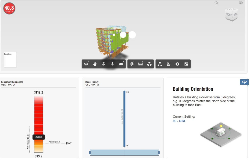
So, we tried adjusting different specs to see which spec had a greater and direct effect to the energy consumption.
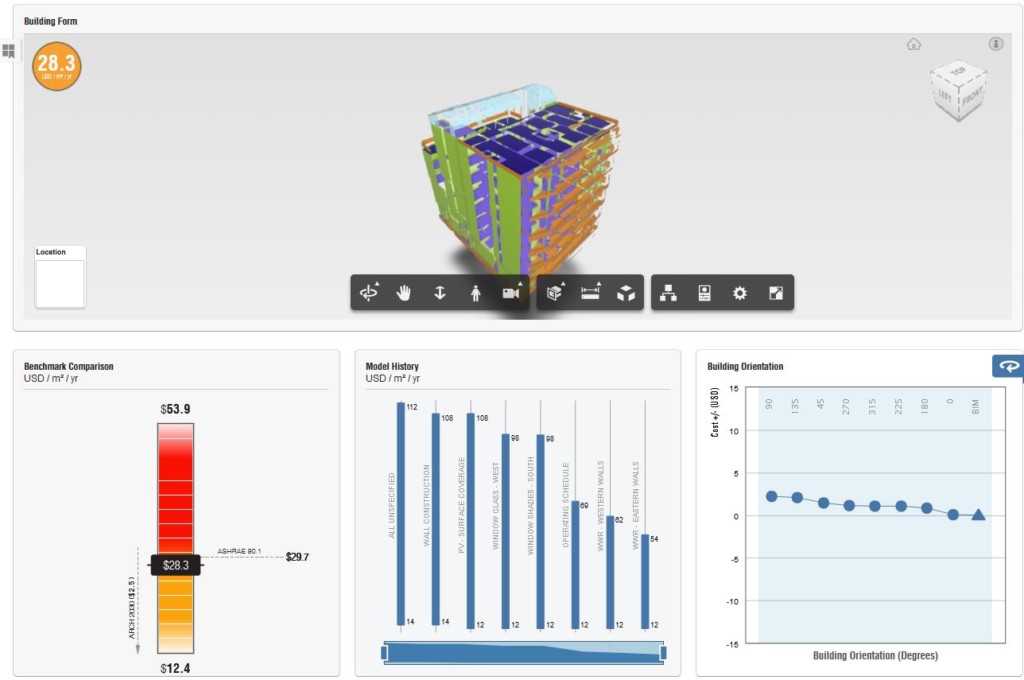
And finally, we were able to reach the energy standards and achieved $ 28.3 per m² /year.
STRUCTURAL ANALYSIS
Structural analysis_ Workflow
For the purpose of the course a stuctural analysis research was conducted in Revit and Robot, where the procedure was studied from scratch.
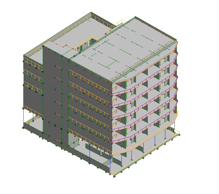
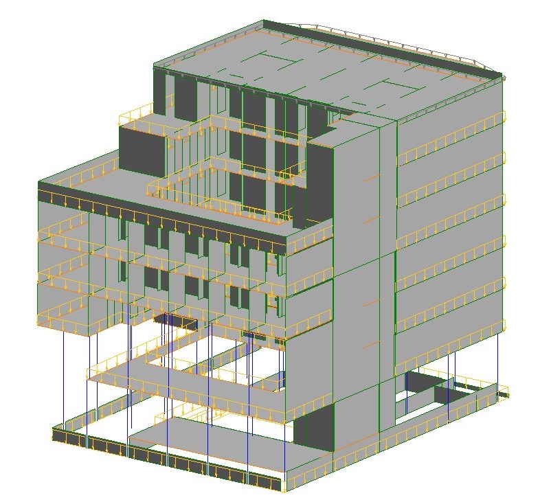
Analytical structure isolation_model
First part was to create an analytical model. For this reason a new view template was created for worksets isolation (structural concrete/timber). Working in worksets helped to see directly what was assigned as structural and what not from the other teams and to detect possible mistakes. Together with other teams (interior team, envelope & structure team) mistakes were detected and elements were put in the correct workset.
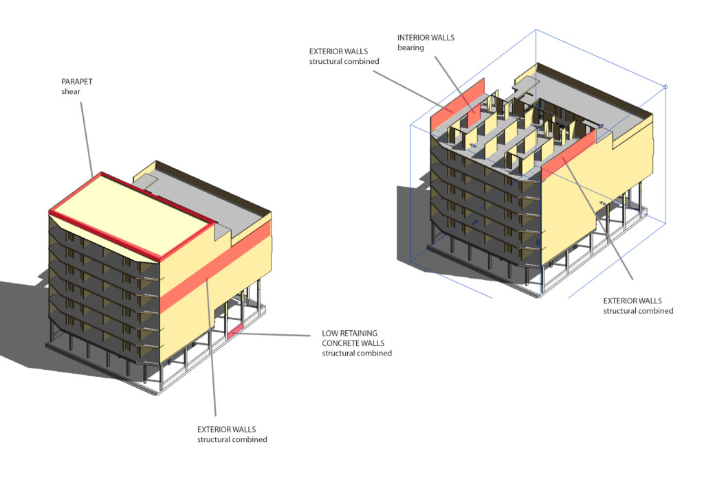
Structural usage_walls
For all the structural walls (concrete and timber) the structural usage was assigned in Revit (Bearing walls, Shear, Structural combined) which is a crucial first step in the analysis. Then a new view template was created to isolate the analytical structural model.
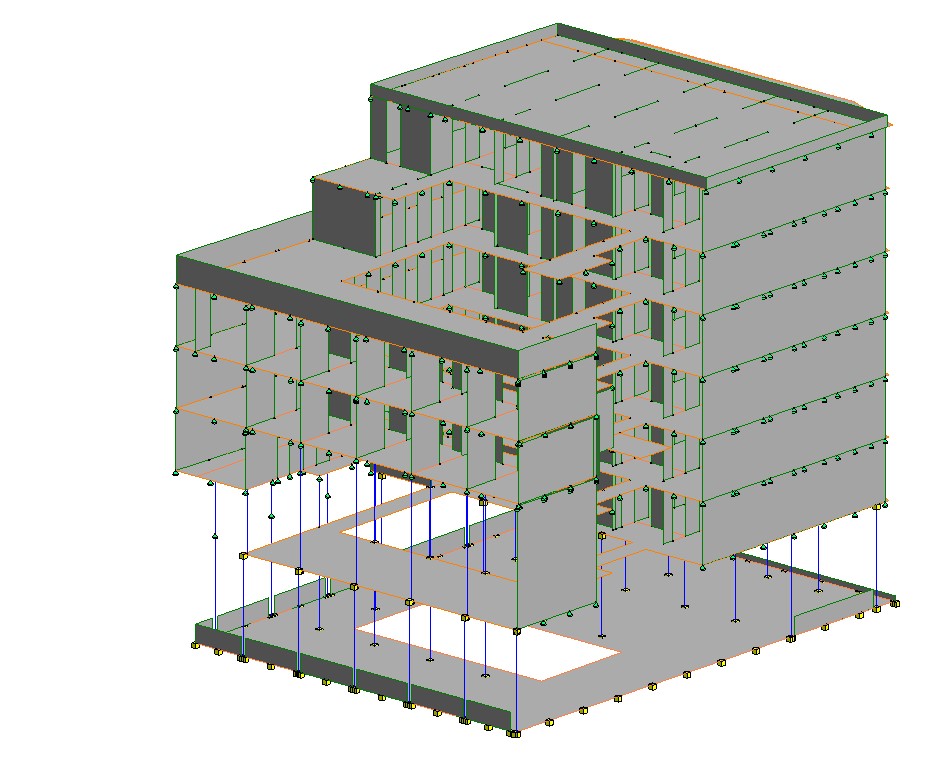
Boundary conditions assignment
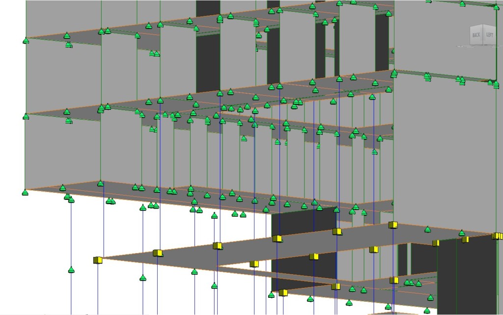
Zoom in the analytical model
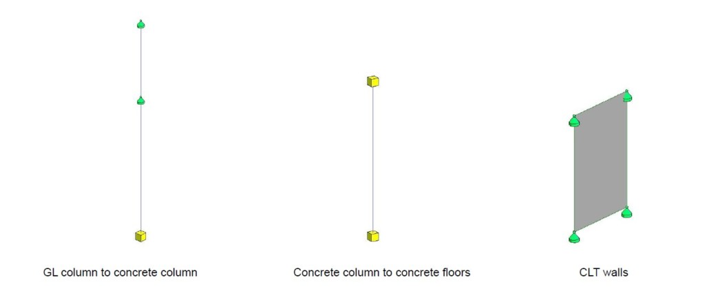
Typical boundary conditions for columns & walls
The next step was the assignment of boundary conditions in Revit (Point, Line, Area) in all elements connections between columns, walls, floors and state specification (Fixed, Pinned).
Loads assignment
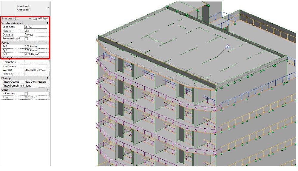
Live loads assignment
Then loads were assigned, live loads and snow loads, given that in Robot all the dead loads are assigned automatically.

The model is ready for exporting in Robot. Normally in Revit, Robot is intergrated , though in the student version used for this analysis Robot could only be installed as a separate software.
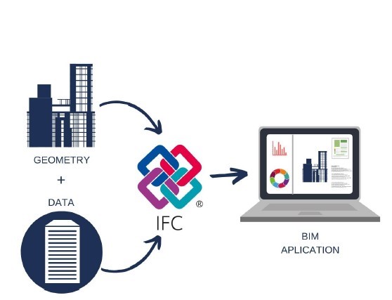
For that reason the model in Revit was necessary to be exported as IFC file and new parameters & settings should be created in order to read each element correctly. When exporting the current model from Revit to Robot with the default settings, some structural walls are missing, as well as all the materials, loads and connections. The specific analysis couldnt run, which makes sense as all the loads and connections should be assigned from the beginning in Robot.
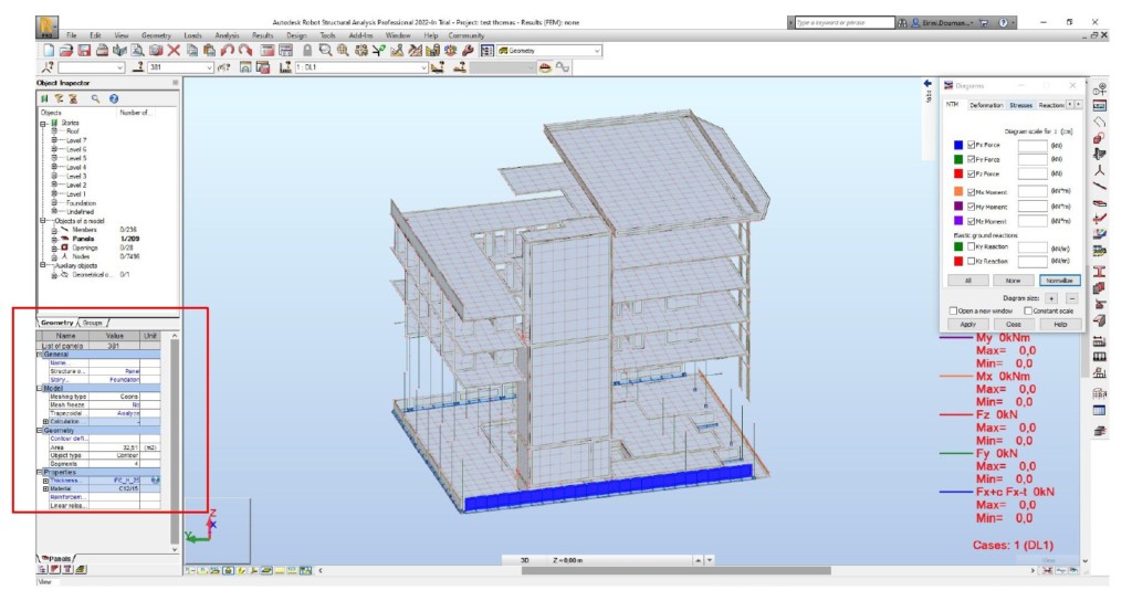
Model in Robot
Conclusions
– Worksets proved critical for the first phase of analytical model creation & the isolation of structural elements compared to wall schedules which due to the big amount of walls were not easily manageable.
– Coordination between different teams is important in this last phase of the analysis, for worksets assignment and model development.
– View Templates helped for structural model isolation when assigning loads and the boundary conditions.
– Export as ifc file from Revit needed an ifc plug in for Revit, which needed time installing it.
– The only compatible file from Revit to Robot which was found were IFC files.
– Robot was easily managed and installed.
– Time needed exploring ifc workflow, for exporting from Revit to Robot, in order all elements, loads, connections, materials to have passed.
– When running the analysis in Robot revealed that no materials and loads had passed from Revit.
– Using an autodesk Revit version that have integrated Robot, probably will have helped creating the analysis with success in less time.
CFD ANALYSIS

Image courtesy of Autodesk
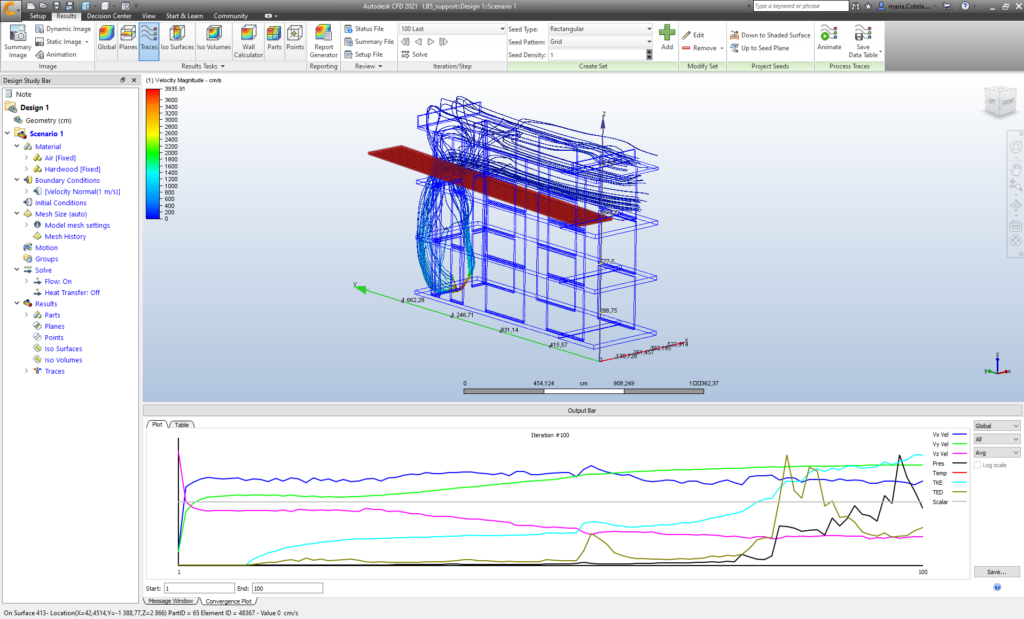
Finally, we performed a CFD (Computational Fluid Dynamics) analysis with Autodesk CFD, which can be installed as a plug-in into Revit. The usual workflow for doing this analysis is either to have the plug-in installed in Revit or to save the file in .sat format, then open Autodesk CFD, create a new project, clean the model and assign materials to it, define the boundary conditions, which can be pressure, temperature, wind direction and speed, etc., and finally run the analysis.
In this case study, the model proved too complex for the CFD analysis, since the program needs perfectly closed volumes. All doors, windows and joints were obstacles that made the calculation too heavy, so the decision was made to simplify the model to be able to run the CFD analysis.
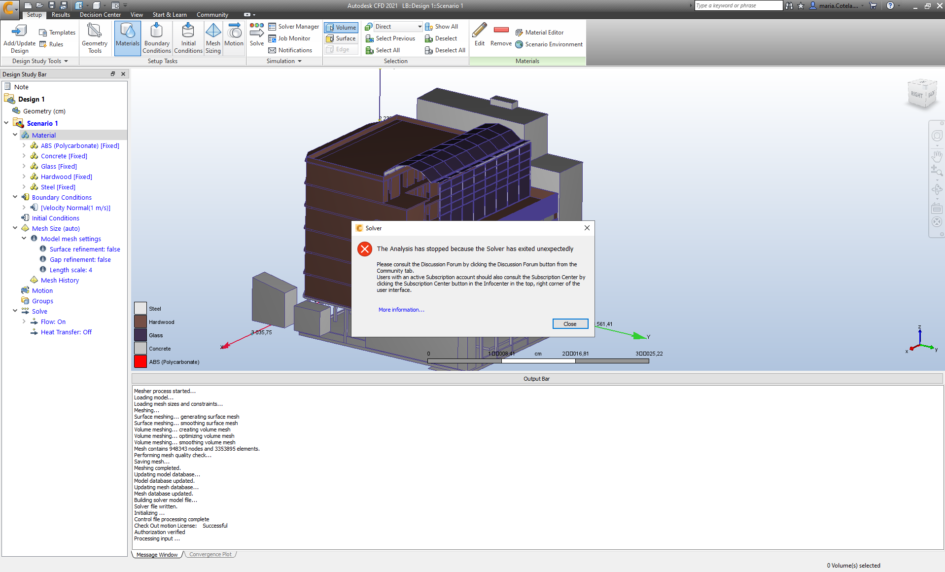
Error message in an attempt to run an analysis for the whole model
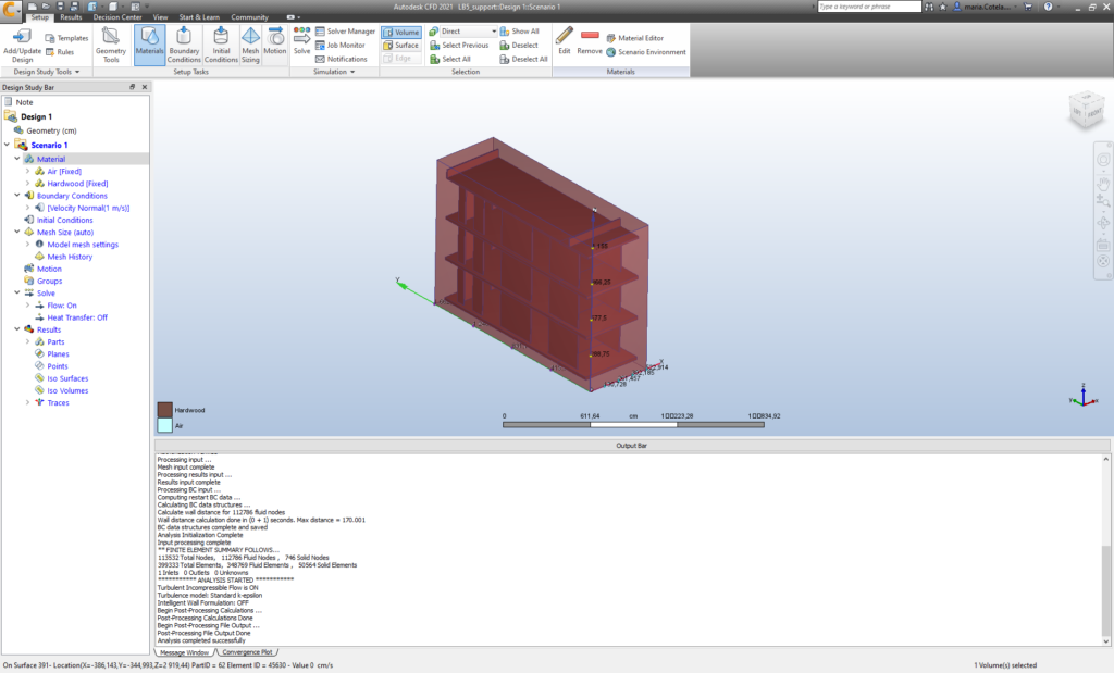
Image of the simplified model
With the simplified model, it was then possible to run an analysis. Once the model was imported into Autodesk CFD and the materials assigned, we needed to create a volume enclosing the model and define it as “air”. Then we introduced different parameters of pressure, air speed and humidity and ran the analysis, getting an estimation of how air would move through the building and what its thermal performance would be.
Results from the calculation.
We played around with the program, assigning different air entrances in the building (from the courtyard and from the facade) and trying different displays.
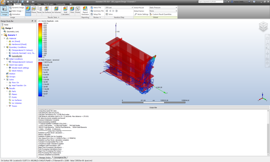
Results with different air sources.
To conclude, although the exercise with CFD analysis was valuable to know more about the Autodesk CFD program, the results of a portion of the building don’t give enough information to affect our design.
Fundamentals of Building Information Modeling is a project of IaaC, Institute for Advanced Architecture of Catalonia
developed at Master in Mass Timber Design in 2021/2022 by:
Student: Maria Cotela Dalmau, Eirini Doumani-Korka, Nataly Dirocie, Esin Zeynep Aydemir
Faculty: Michael Salka