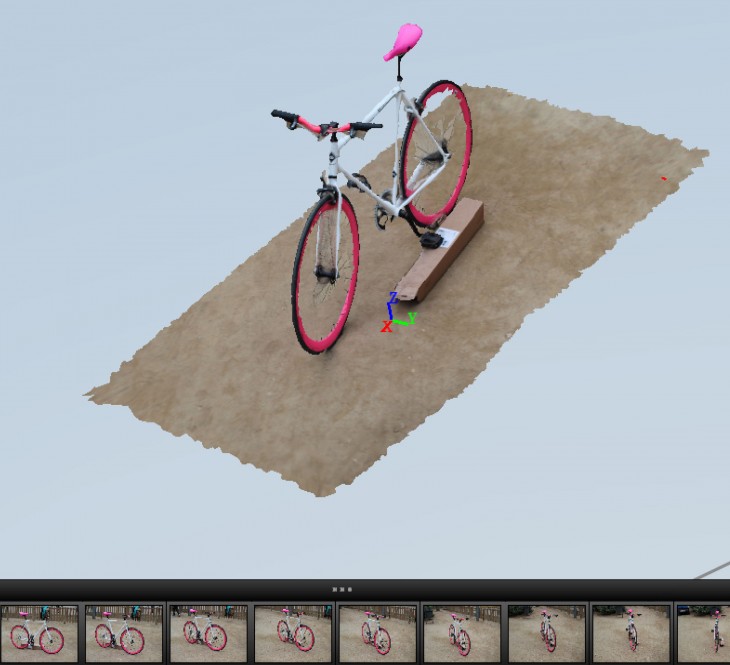
STEP 1: 123D Catch
To start with, I took pictures to the selected object, using a DSLR camera and a tripod. These pictures covered entirely the object, from a 360 degree visual.
Using 123d catch software, and with the given pictures, I produced a 3D model of the bicycle. Later on, I exported the 3D model as an .OBJ and imported into Rhinoceros. I Used the model as a reference to measure every component of the bicycle, and then started my drawing from scratch.
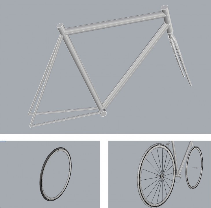
 STEP 2: Frame, Rims and Wheels
The first component I drew was the frame. Every single component is attached to it so I decided it was a good starting point. First, i drew lines, with the lengths and angles I had measured from my 123D Catch model. I then used the command pipe to generate the tubes: Top tube, seat tube, head tube and down tube, giving the correct diameter in each case.
To follow with, I drew the wheels with circle and pipe commands.
For the Rim I had to draw the section with control point curve command, taking into account its particular shape and details. I then used the command revolve over an axis.
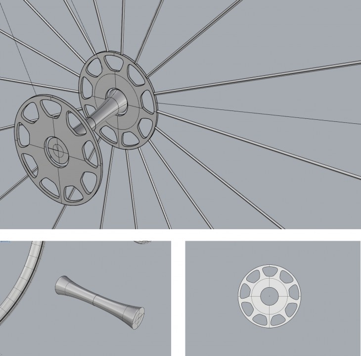
STEP 3: Hub, Disk Brake Rotor and Spokes
Having drawn the wheels I started adding some details. For the Hub I drew a line, half a curve which I then mirrored to achieve symmetry and then used the revolve command to get the surface.
For the Disk Brake Rotor I first drew the contour and the whole in it with control point curves, then generated the surface selecting the contour and trimmed the whole out. I used the command extrude to achieve the width.
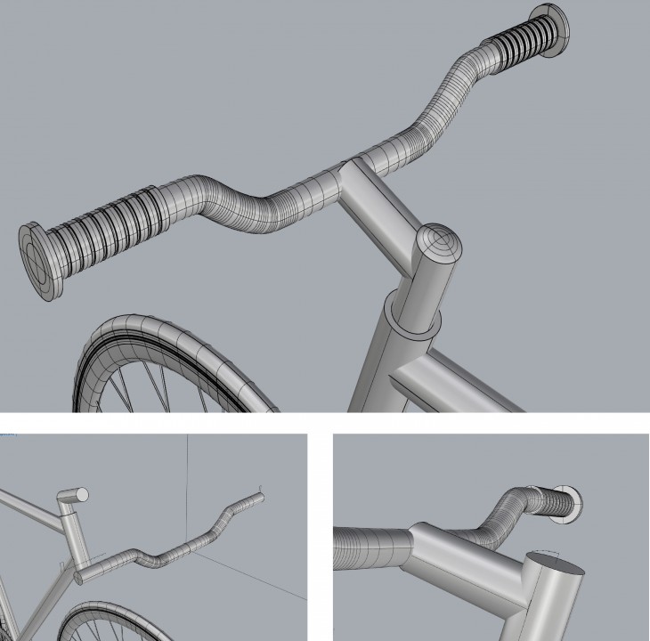
STEP 4: Handlebar and Grips
Using the control point curve command I drew the first half of the handlebar’s axis and then mirrored it to achieve symmetry. Later on, I used the pipe command to accomplish the shape.
For the grips, I drew the section first with polyline command and then used revolve through the handlebar axis to get shape.
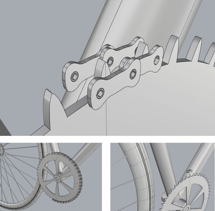
STEP 5: Chainring and Chain
Regarding the chainring, I first drew the contour and the whole in it with control point curves, then generated the surface selecting the contour and trimmed the whole out. I used the command extrude to achieve the width. Basically, I repeated the process I used when drawing the Disk Brake Rotor but with a different shape.
For the chain, I first drew one module with control points curve, mirroring curves to get it symmetrical. Later, I joined the mirrored curves, and built a surface from it, which I then extruded. I duplicated it with copy command and I had my first link. Using copy, rotate with reference, arraypolar, move commands I got the complete chain. Notice that there are female and male module, to achieve the connection between them.
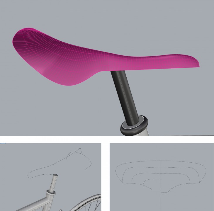
STEP 6: Seat
This Step was probably the most difficult one to achive, maybe because It is my first time modelling Rhinoceros and I find it difficult to draw a curve in 3 axis. Through all the steps I used the PointsOn command, which was really helpful while drawing these curves.
The one thing I founded really complex was how to manage the Cplanes. But I guess, it gets easier with more practice. For the seat, I drew the curves with control point curve command, first the contour and then the edge. Also, I added some inner lines to give the exact shape I wanted, and then finally after trying loft, tween curves, sweep1, amongst others, I found the command Network Surface.
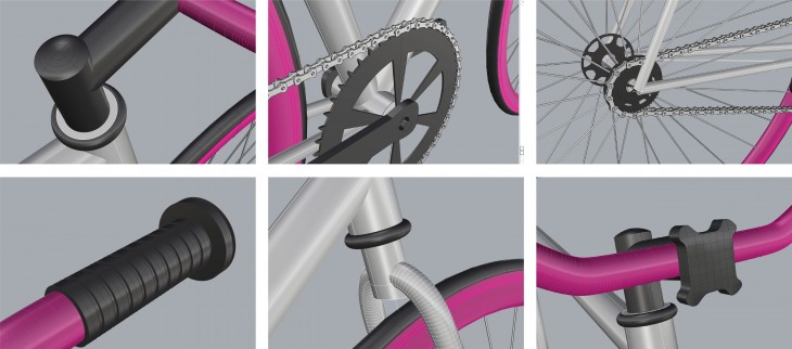
 DETAILS
Having the main components done, I started adding detail to my drawing. The whole process was done looking at the 360 pictures I had taken of my object.
For these details and the whole model I used the following commands: Extrude, Rotate, Revolve, Sweep1, Loft, Control Points Curve, Handle Curve, Mirror, Trim, Extend, Copy, Line, PoinsOn, Surface from 3 or 4 corner points, Surface from planar curves, Network Surface, Scale.