FEEDBACK LOOP FOR 3D-PRINTING
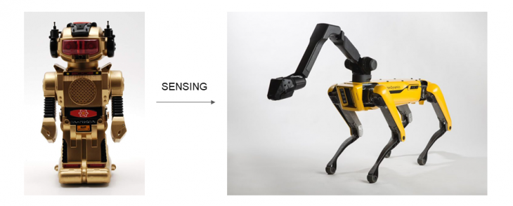
CONTEXT: Sensors and control algorithms have resulted in unprecedented growth in the field of robotics in the past two decades. Industry 4.0 aims to integrate sensors and algorithms in the manufacturing industry on a similar pretense.
AIM: This project aims to integrate sensing in a traditional 3d-printer to gauge the print quality and provide feedback to act on based on the data. This project fits well in the context of printing from scrap plastics for a cradle to grave production

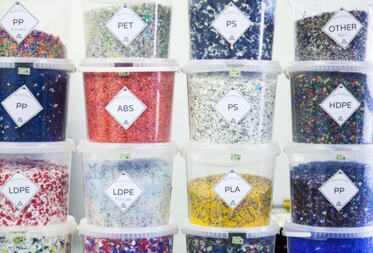
PROBLEMS: There is a wide range of plastics available in the industry. To print any of these, a test print needs to be run by varying properties like print speed, extrusion temperature and more. This relies on a cumbersome, meticulous visual inspection. We aim to automate this procedure of calibration.
HARDWARE TOOL: In the beginning, we developed a pellet extruder with the hardware including a wood-screw, 3-10W band heaters, a NEMA-17 motor and a thermistor in series with 3 parallel relays to regulate temperature. However, a NEMA-17 motor provided insufficient torque. Hence we used a pellet extruder by WASP.

HOW: Geometric parameters like layer height and extrusion width were ideal for feedback. Layer height is material independent and thus remains constant. Thus we chose to control the extrusion-width.
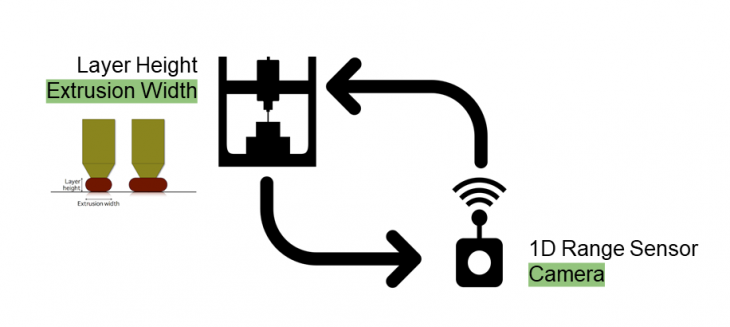
An RGB camera was used to sense changes in extrusion width and act accordingly.
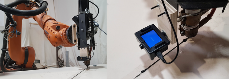
SETUP: A Kuka KR-150 was used with a WASP pellet extruder. A small action camera was mounted about 8cms away from the extruder so that it could view the recently printing path (with a slight delay)
ACTION: There were 3 parameters to choose from for the action:
- Robot Speed
- Printing Temperature
- Extrusion Speed
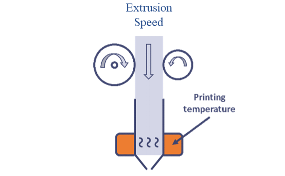
We chose to act on the extruder motor speed as it was the easiest to implement as a proof of concept. But conceptually the robot speed or the print temperature would work in a similar fashion but through VAR proxy and lethargic thermal inertia respectively.
STEP 1: OpenCV Script : A straightforward OpenCV script in Python, involving the detection of two parallel lines. Based on the number of pixels and the distance, we can calculate the actual distance between the two detected lines. Based on the extrusion width we require, an error can be calculated which can correspondingly be related to a change in RPM. A simple proportional controller is used to calculate this correspondence.
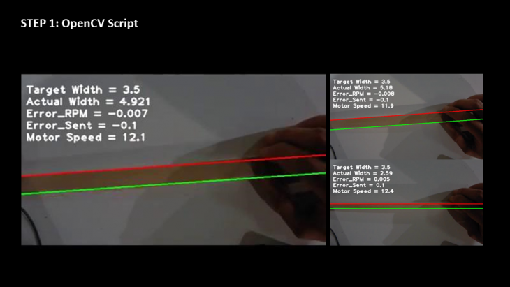
STEP 2: Linking OpenCV script to the extruder control : The most troublesome aspect of the procedure was to establish serial communication between the Python script and the Arduino controlling the WASP extruder. After arduous trials, only binary information could be managed to be sent over the Serial port. Hence the images show an ‘Error_Sent’ parameter which is mapped to +0.1 (1) in the case of under-extrusion or -0.1(0) in the case of over-extrusion.
STEP 3a: 3D-PRINTING: In the first test, the camera was too far apart. The VGA camera (640×480 pixels) had poor resolution to distinguish the two lines. Hence the camera is moved closer.
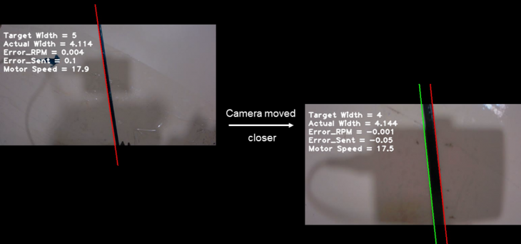
TEST 3b: UNDER-EXTRUSION: In this case, initially, the required extrusion width is less than the target width accounting for a positive error in rpm. The extrusion width increases from 3.1mm to 4mm during this experiment
TEST 3c: OVER-EXTRUSION: Error = 0.1 (Too high)
In this case, initially, the required extrusion width is more than the target width accounting for a negative error in rpm. However, the error sent (0.1) is too high which causes the motor to stop.
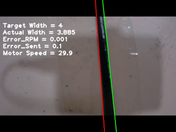
TEST 3c: OVER-EXTRUSION: Error = 0.05 (Much better)
In this case, the error sent (0.05) is better which slows the motor down until the extrusion width reaches from about 3.5mm to about 2mm.
HURDLES: Following were the hurdles we faced
- PID Speed Control
- Delay due to the position of the camera (offset to the extruder)
- OpenCV algorithm could be better to accommodate slanting lines
FUTURE RESEARCH:
- More robust OpenCV detection (Filtering or better algorithm)
- Additional control like extrusion temperature or robot speed
- Real-time feedback during the entire print
FEEDBACK FOR 3D-PRINTING is a project of IaaC, Institute for Advanced Architecture of Catalonia developed at Master in Robotics and Advanced Construction (M.R.A.C.) in 2019 by,
Students: Apoorv Vaish | Sebastian Voigt | Subhash Prajapat | Owaze Ansari
Faculty: Angel Muñoz
