*project developed as part of MRAC W2.2 SENSE-digitising the physical world, in collaboration with Georgia Tech (Spatial Futures Lab) 2019/2020
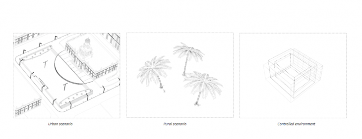
In the context of developing multi-system drone choreographies, the project is testing the possibility of concatenating multiple drone building ‘levels’ for achieving easily deployable, contextually versatile service structures for jungle, rural or urban interventions. Trained in a controlled environment (the drone cage), the system is designed and thought of as a ‘backpack’ rig that a single explorer could set up and deploy in a matter of days, responding to urgent requests.
/ CONCEPT
Interfacing tensile kangaroo simulations with Fologram- initial tests
Starting from fluid tensile simulations in Kangaroo, in order to test the responsivity of working with real time physics in AR, receiving and responding to user input during a live connection between the agents involved, the project set out as an objective to develop a real-time modelling tool for setting pop-up tensile pavilions.
/ PHASES
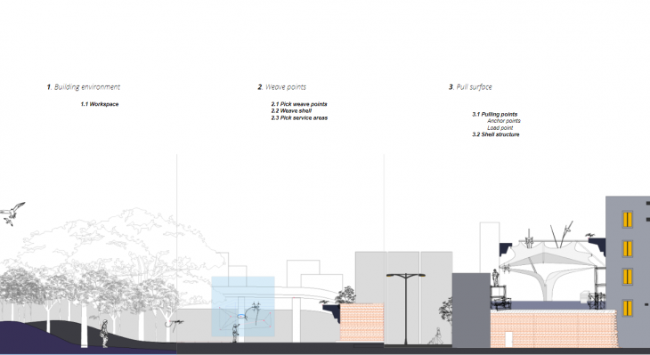
The system would be deployed in three sequencial phases:
- Build environment
- Weave pavilion
- Deform pavilion
/ Phase 1: BUILD ENVIRONMENT
In order to deploy a tensile structure, pin points must be first defined. At this stage:
- simulation context is being defined
- the drone’s mission is to fasten a rope around the pin points, defining the bounding edges of the tensile surface
- based on the simulated context, the drone path is being calculated with the purpose of performing the fastening mission
A. Generative context simulation
A context that can be later be modified by the Fologram user through adjusting the number and the position of the generated elements through the Parameters section is first simulated. In the first test, cylinders are used to represent low-poly placeholders for trees.
B. Generative drone flight path
Once the context has been determined, the drone can then simulate a path to fasten the initial rope lengths around the pin points, defining the surface edges.
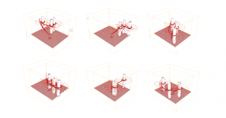
C. Drone rope deposition
During the autonomous drone flight, the drone deposits the rope in AR visually displaying the fastening procedure. For this purpose, the Fologram pointer tracker has been used for initial tests, and the drone live position published from ROS is being used for the drone flight tests.
Initial drone rope deposition test
D. Drone flight
Initially, the drone flight has been tested manually. Later on, it has been tested autonomously, following the generated path and depositing rope.
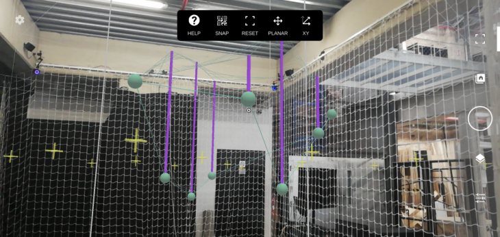
/ Phase 2: WEAVE STRUCTURE
Now that the pin points have been defined and the initial edges of the surface have been deposited, a weaving protocol is deployed. At this stage:
- Surface edges are broken into control points
- Surface weaving is split in two passes (initial pass, infill pass)
- The user can pick each one of the control points and move them through space, defining the first pass weaving points
- The drone then autonomously deploys the weaving protocol, adding fastening loops around each of the control points

Weaving passes
A. Control points
B. Weave surface deformation
C. Double mesh
In order to provide three dimensional space for nesting services, the initial woven shell is doubled, being propped up with struts.
/ Phase 3: DEFORM STRUCTURE
Once the woven structure is woven by the drone, it is ready to be deformed by hosting service objects. In this stage:
- Fologram camera pointer tracker is being used for deforming meshes
- During drone flight, drone live position is being used as the deformer attractor point
- Control points are being defined on meshes, in order to enable user control (drone picking points and re-simulating the tensile structure, or hand-picking points via Fologram on phone)
A. Camera pointer tracker
B. Drone deformer
Light-weight meshes are being processes in real time on Hololens and fologram and baked as the drone saves mesh positions.
C. Control points