CASE STUDIES

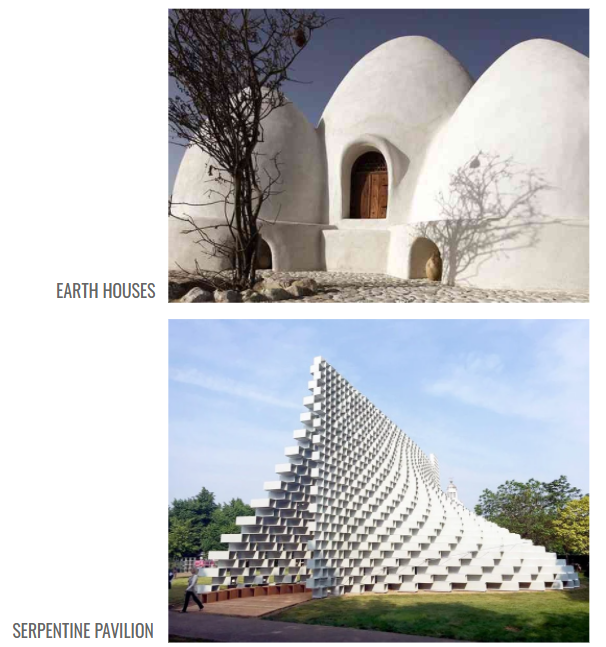
The earth houses by Nader Khalili relate to our project in their structural form. Arches, domes and vaults built from ‘superadobe’ are formed into single and double curvature compression shell structures. The self-supporting arched roof structure can be one single space, or form more spaces through merging multiple arch systems.
In terms of lateral stability, the windward surface of these domes are in tension, the red arrows. The leeward surface of the domes are in compression, the blue arrows.
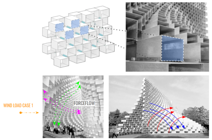
The 2016 Serpentine Pavilion, by BIG architects, relates to our project in its fabrication method. Created from pultruded fiberglass “bricks”, the structure is generated by “warping” a wall made of only two elements, bricks and joints. We also intend to use bricks in a curved structure.
In terms of lateral stability, this structure behaves similarly to the domes where the windward surface of these domes are in tension, the red arrows. The leeward surface of the domes are in compression, the blue arrows.
DESIGN INTENT

Our structure is created from overlapping domes, which form arches and vaults in the interior spaces. We intend to use a grid below the shell, and we would specifically look at how grids can be optimized based on Principle Stress lines and Forceflow lines in a shell analysis.
Our material is salt bricks, but we are using concrete in our analysis.
STRUCTURAL PRINCIPLES
This research project is an exploration on how the principal stress lines can influence the grid design and how different shells and grids can impact the structural stability of domes.
We will study the following structural principles:
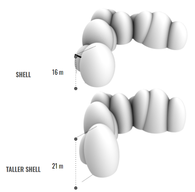
- Solid shell: comparing different dome heights
- Grid: comparing different grid systems
First, we are going to analyze the structure as a shell. Then we are going to look at the principle stress lines and the forceflow lines. Based on these, we are going to design a grid that follows the direction of the lines.
We will also design a simple square grid and simple triangular grid for comparison to test if our method is effective.
Because designs are always changing, we want to see how the principle stress lines and the grid design would change by increasing the height of the dome. We expect that the lines would simply scale up in the Z-direction. We are only performing this analysis to compare the behavior of the lines. The structural performance of the taller shell will be worse.

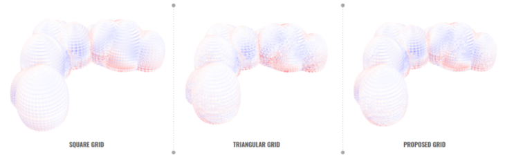
- The Square Grid is made by extracting the quadrilateral curves of the original shell’s mesh.
- The Triangular Grid is made by triangulating each Quad
- The Proposed Grid will begin with the square grid, but only the quads that intersect the Principle Stress lines are Triangulated
Between the Square grid and the Triangular grid, we expect that the triangular grid will have the best structural performance, but the least efficiency. Our aim is to prove that the proposed grid will have results somewhere in between the Square grid and the Triangular grid.
ANALYSIS & RESULTS
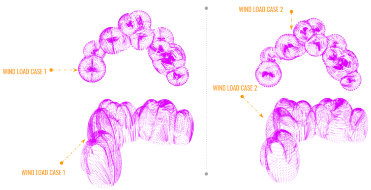
SHELL | Principal stress lines
Principal stress lines are important because they distinguish between Tension and Compression. The red lines are in Tension, the blue lines are in Compression. For the proposed grid design, only the quads that intersect Principle Stress lines are Triangulated.
TALLER SHELL | Principal stress lines
As expected, the principle stress lines would simply scale up in the Z-direction. As a result, we would scale up the location of the triangular grids in the Z-direction.
SHELL | Forceflow lines

Forceflow lines are the resultant forces. They don’t indicate whether they are in Tension or Compression, but they can also be used to design the grids.
TALLER SHELL | Forceflow lines
As expected, the principle stress lines would simply scale up in the Z-direction.
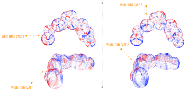
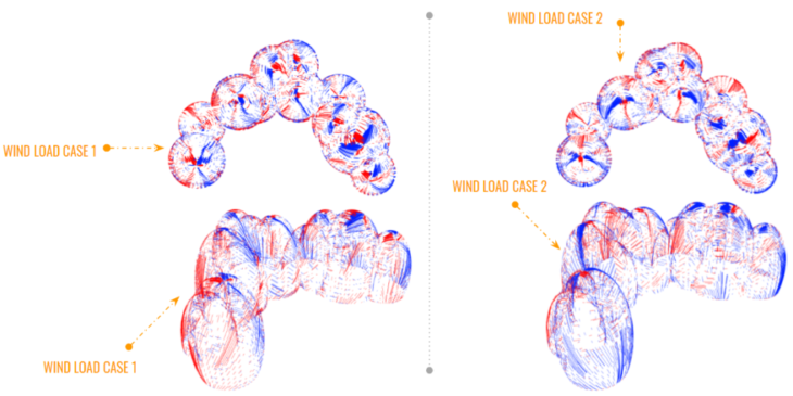
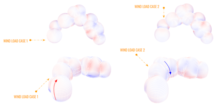
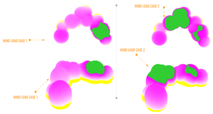
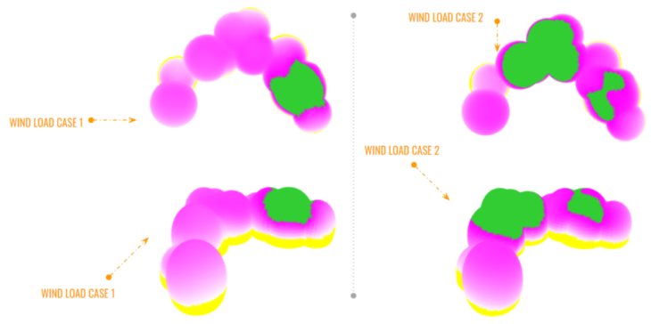
SHELL | Wind Load Utilization
If using shells, we could reduce the thickness in the areas that have the lowest utilization or create openings in these locations.
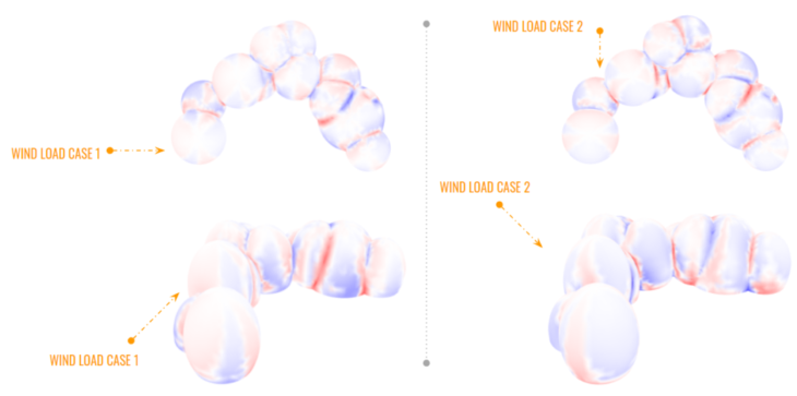
SHELL | Wind Load Displacement
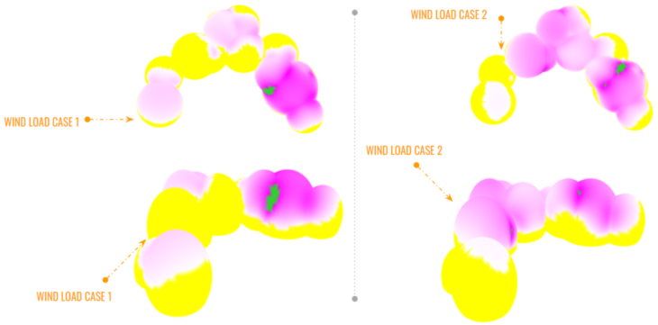
Darker pink represents higher displacement. The lowest displacement is in Yellow. The highest displacement is in green.
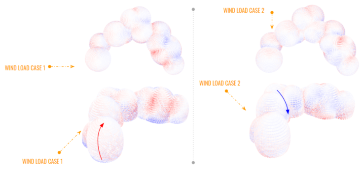
SQUARE GRID | Wind Load Utilization
As expected, the windward surface of the domes are in tension. The leeward surface of the domes are in compression.
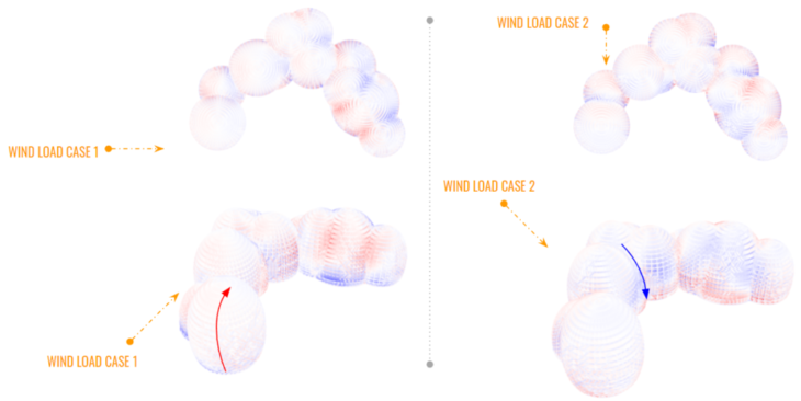
TRIANGULAR GRID | Wind Load Utilization
The tension and compression behaves similarly as the previous grid.
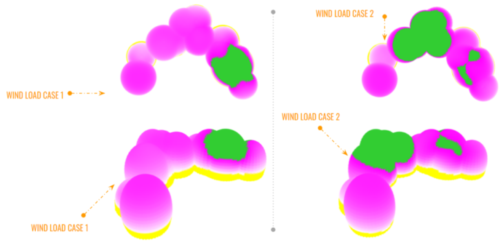
PROPOSED GRID | Wind Load Utilization
In terms of utilization, results in all 3 grids are visually similar.
SQUARE GRID | Wind Load Displacement
Darker pink represents higher displacement. The lowest displacement is in Yellow. The highest displacement is in green.
TRIANGULAR GRID | Wind Load Displacement
PROPOSED GRID | Wind Load Displacement
In terms of displacement, results in all 3 grids are visually similar.
GRID – SHELL ANALYSIS | Wind load 1 Data Comparison
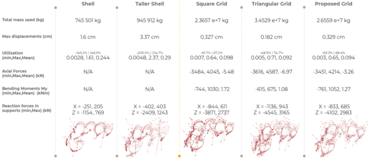
In terms of displacement, the proposed grid performs worse than the Triangular grid, as expected, but has similar performance to the Square grid.
The proposed grid weighs much less than the triangular grid and has a higher utilization, making the proposed grid more efficient.
Since we want the least amount of bending, and more compression and tension, the Triangular grid is the most favorable in axial force and the proposed grid is second most favorable.
The reaction at supports are an indicator of where the grid is active. If one of the supports doesn’t take any load, then the grid is not transferring load to that support.
GRID – SHELL ANALYSIS | Wind load 1 Data Comparison
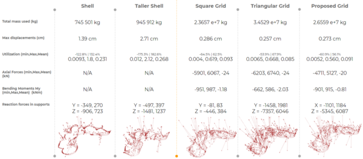
In terms of displacement, the proposed grid performs in between the Triangular grid and the Square grid, as we hoped to prove.
Since we want the least amount of bending, and more compression and tension, the Triangular grid is the most favorable in axial force and the proposed grid is second most favorable.
The Shell analysis results are as expected.
CONCLUSION
As expected the triangular grid has the best structural performance, but the least efficiency. We hoped to prove that the Proposed grid will have results in between the Square grid and the Triangular grid. We were successful in proving our theory, however, the Proposed grid was more similar to the Square grid than we had hoped. In some cases the Proposed grid performed even worse than the Square grid, which is something worth further exploring.
TOPIC FOR FURTHER DISCUSSION
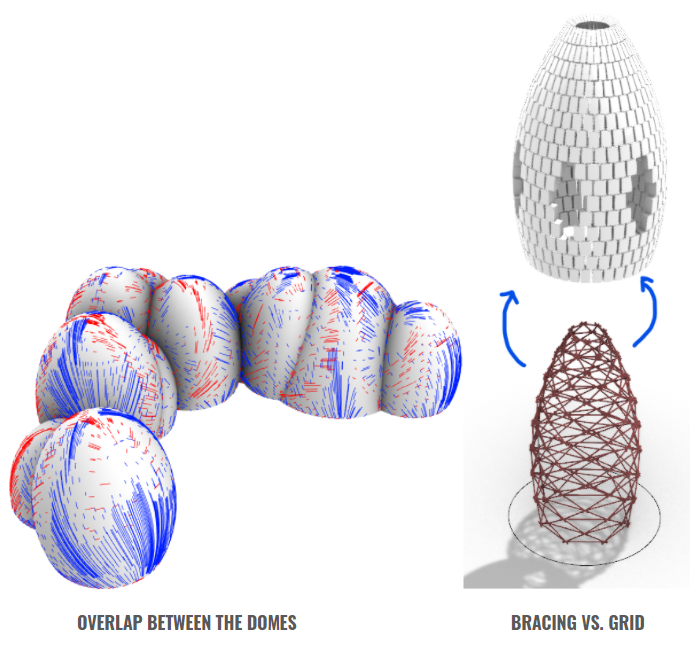
OVERLAP BETWEEN THE DOMES
We were curious about exploring the overlap between the domes, specifically the transitions between the shells and how the grids would be designed in these areas. Visually, we don’t see anything particular happening in these areas.
BRACING VS. GRID
We were also curious about how our analysis would differ if we used smaller bracing elements instead of a beam grid.
Espejo is a project of IAAC, Institute for Advanced Architecture of Catalonia developed in the MaCAD 2022 by:
Students: Amanda Gioia, Rodrigo Alvarez, Ara Keuroghlian, Jumana Hamdani and Abed E. Badran
Faculty: Manja van de Worp, Matthew Gabe