Introduction
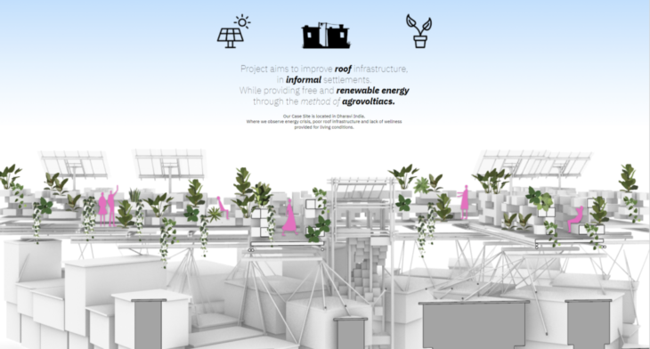
Figure 1 : Concept for design
Our Studio Project aims to improve and activate roof infrastructure in informal settlements, while providing access to generate solar energy through agro voltaics. As a case site we have chosen Dharavi, in Mumbai, India, one of the most populated informal settlements in India.
As we can see in the representational section on the screen our structure will float on top of the existing houses in the settlement, and will house agriculture and solar panels.
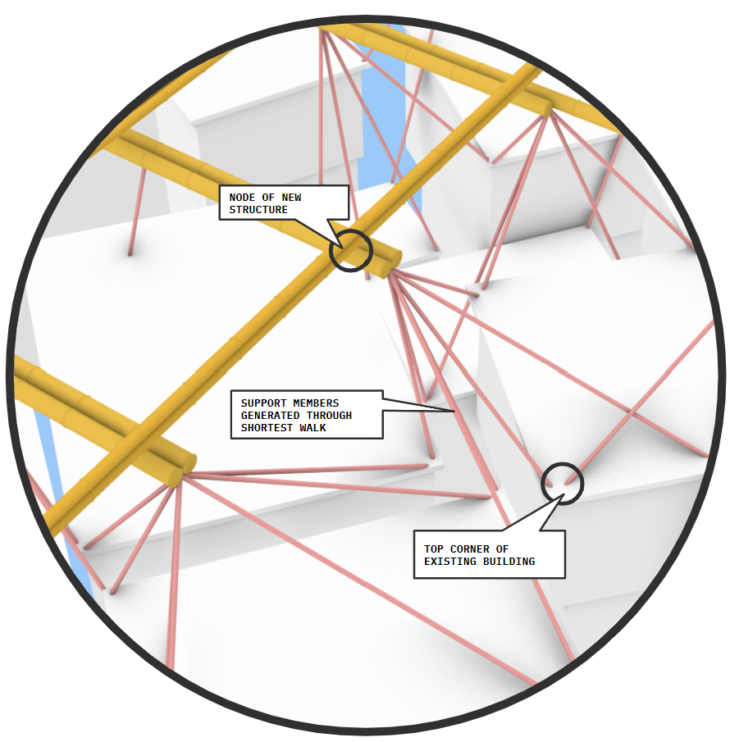
Figure 2 : Identifying Support Members
The support Members are drawn by joining the top corners of the existing building edges to the intersection nodes of the floor beams.
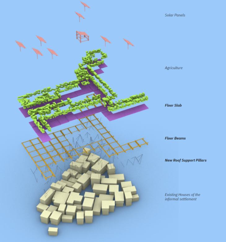
Figure 3 : Structural hierarchy
Being supported by the existing building infrastructure, The structural elements are divided into 3 parts, Support Pillars, Floor Beams in a 4x4m grid And the floor, which will house the micro unit cells and the solar panels. Computationally we use shortest walk to join the support members from the top corners of the existing building edges to the intersection nodes of the floor beams.
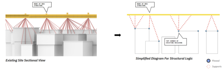
Figure 4 : Structural diagram
Our scheme for structural support is divided in three layer, Floor marked in yellow, Multi support pillar in red and Wall edge for placing supports.
The support pillars are connected to the top edge of walls underneath. And all the supports are pinned.
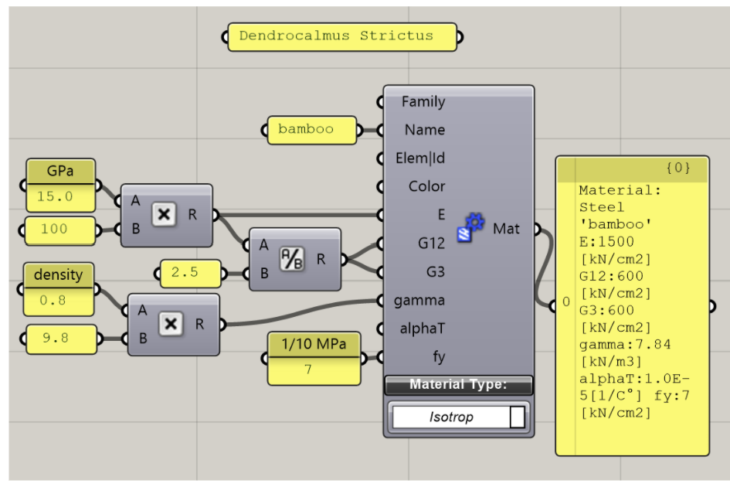
Figure 5 : Material properties
Bamboo (Dendrocalamus strictus)
E : 1500 kN/cm2
G12 : 600 kN/cm2
G3 : 600 kN/cm2
Gamma : 7.84 kN/m3
Fy : 7.0 kN/cm2
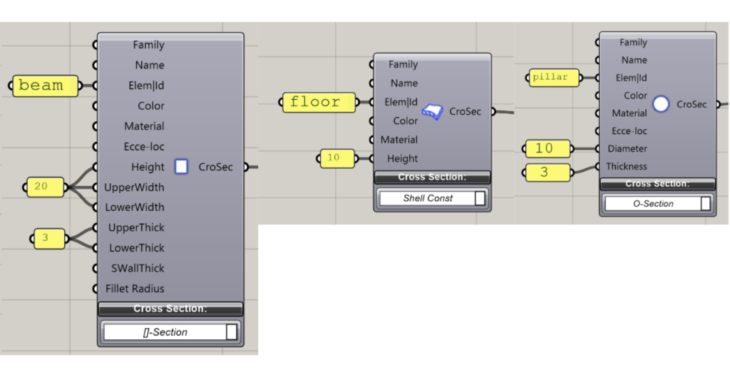
Figure 6 : Cross sections for the elements
For the material, we used value for male bamboo. For the cross section, we used one bamboo for a pillar and 4 bamboo for a beam, and the height of the floor is 10cm. All the values are derived from diameter of bamboo as a unit.
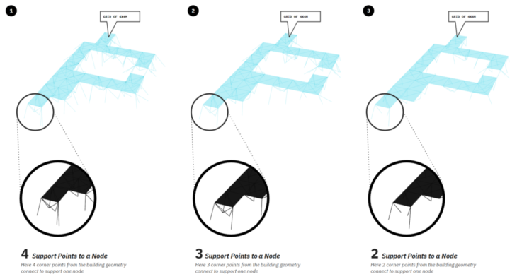
Figure 7 : Analysis methodology
Our analysis is a quest to discover how many support pillars are required to take the load on each node of the 4x4m floor grid.
For this we do a comparative analysis, between 4, 3 and 2 support pillars to come with a conclusion of an optimum number of pillars.

We tried to decrease the number of pillars at each beam sections.
This is the model for 4 pillars each at beam sections. Relatively high deformation within the model was seen at a slab corner.
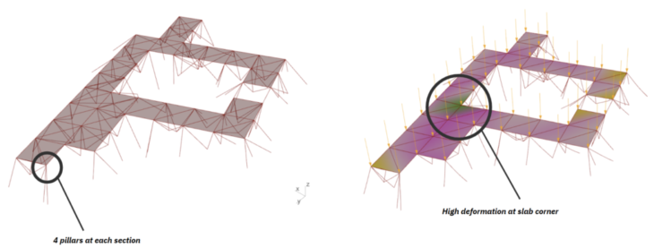
Figure 8 : 4 pillars model
Loads : self weight + live load 2.5kN/m2 Self weight : 36977.9 kg Maximum displacement : 2.8 mm
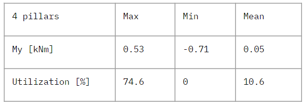
The values for bending moments and utilization was not so much, though there was a concentration of bending moment at the columns are very close to the building underneath, because they are placed horizontally.
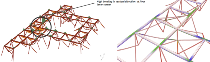
Figure 9 : Results for My and utilization (4 pillars)
And then, we reduced the number of pillars into 3 for each section. Deformation remains high at floor inner corner with reduced pillars. Although, no addition of other high deformation was detected.
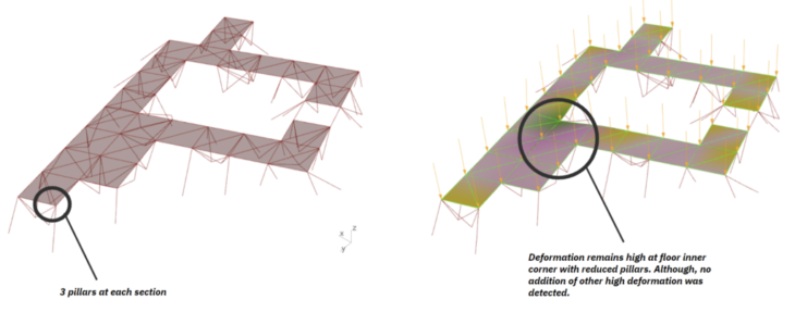
Figure 10 : 3 pillars model
Loads : self weight + live load 2.5kN/m2 Self weight : 35837.0 kg Max displacement : 6.7 mm
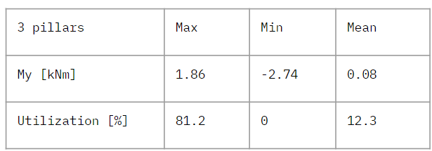
As expected, utilization has increased with a reduction in pillars supporting the floor, as has vertical bending. Since this is a better use of material, we should consider local bracing strategies, since overall bending is low.
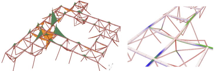
Figure 11 : Results for My and utilization (3 pillars)
With a reduction to 2 pillars supporting the floor, we see that not only has deformation increased at the floor corner, but it has also increased dramatically at the adjacent edge. 2 pillars may be insufficient to support the floor in these instances. Max capacity for displacement calculated from span is 16mm. So this displacement is close to the limit.
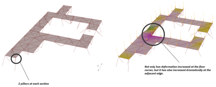
Figure 12 : 2 pillars model
Loads : self weight + live load 2.5kN/m2 Self weight : 34768.4 kg Max displacement : 11.1 mm
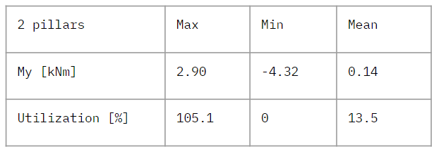
Predictably, utilization has increased with a reduction to two pillars supporting the floor, though in this case the utilization exceeds the capacity of our beam material (bamboo). Bending has also increased over four-fold from the four pillar iteration, thus we could conclude that two pillars only in the current configuration would be insufficient in terms of support for our structure.
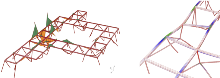
Figure 13 : Results for My and utilization (2 pillars)
In this iteration, we placed 3 pillars at the section which has highest deformation. And 2 pillars for the other places. With the addition of local support we can see that deformation is reduced at the inner corner of the floor and completely alleviated at the adjacent edge
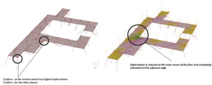
Figure 14 : adapted 2 pillars model
Loads : self weight + live load 2.5kN/m2 Self weight : 34945.5 kg Max displacement : 6.5 mm
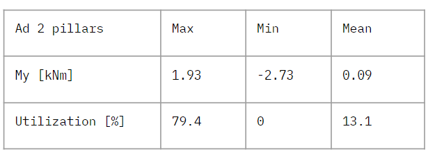
Maintaining 2 pillars globally and adding additional pillars to address local deformation and bending has resulted in good utilization, within the material capacity of the beams, and a reduction by around half in bending overall.
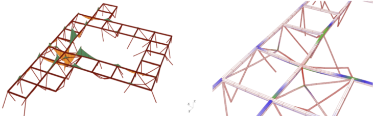
Figure 15 : Results for My and utilization (adapted 2 pillars)
These are the comparison of 4 models we showed. The models, 3 pillar and adapted 2 pillar showed similar results in these values. Max utilization in adapted 2 pillar was lower than 3 pillar, while mean value was slightly increased. The loads were distributed better in adapted 2 pillar. Decrease of total amount of self weight was more than 2000 kg between first model and adapted 2 pillars. For this model, we could use 3 pillars for the section which close to the building underneath, and 2 pillars for the other sections.
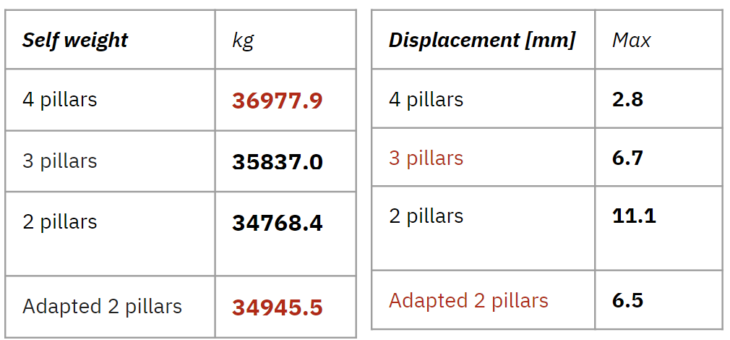
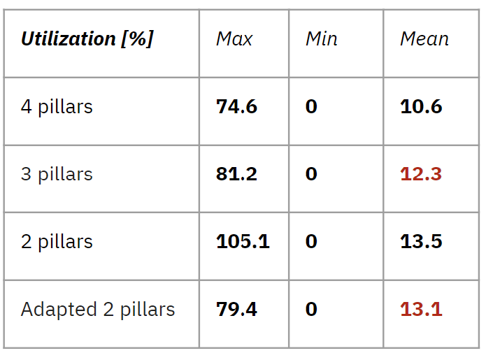
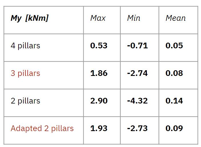

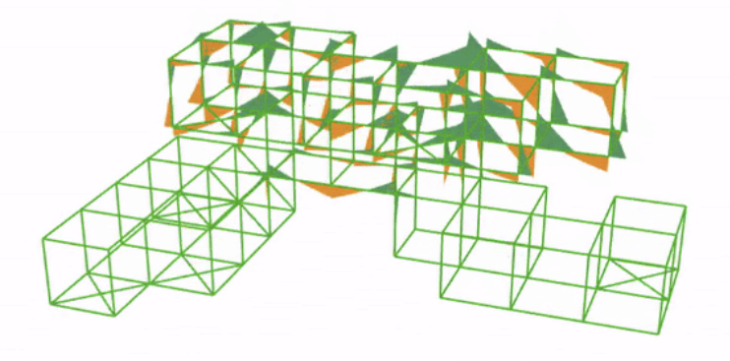
Figure 16 : Bracing generation
For our micro cells which were created with cellular automata, we needed to find a way to create stability so we decided to approach this by looking at unit cells for adding bracing. We chose to look at the global effect of changing unit placement on a greatly reduced portion of the total structure – under 2m high and 4m wide.
3 unit cells were chosen based on their ability to resist vertical loading – given that our structure has long spans, vertical loads are our main concern. We set up a workflow that cycles through possible unit cell placements over all vertices in the main structure, placing each as bracing units in Karamba, and analyzing the global structure.
We had 2 objectives – minimize displacement and minimize material, or the amount of bracing.
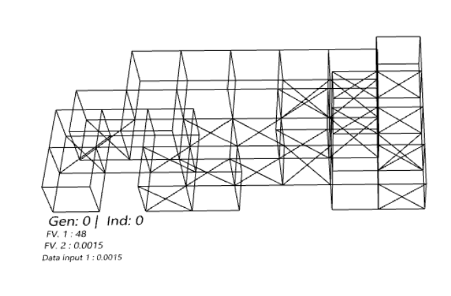
Figure 17 : Model geometry (Gen 0)
In the first individual we can see high deformation in the cantilever at left, but displacement is low in general. We have high utilization in the portion of the structure with 2m cantilevers, and very low utilization in the lower part of the structure.
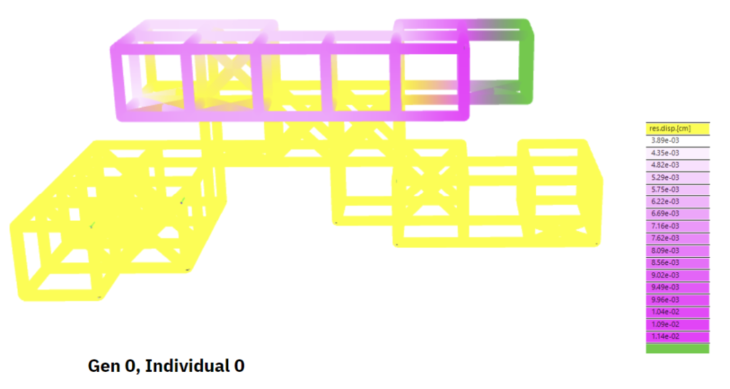
Figure 18 : Displacement (Gen 0)
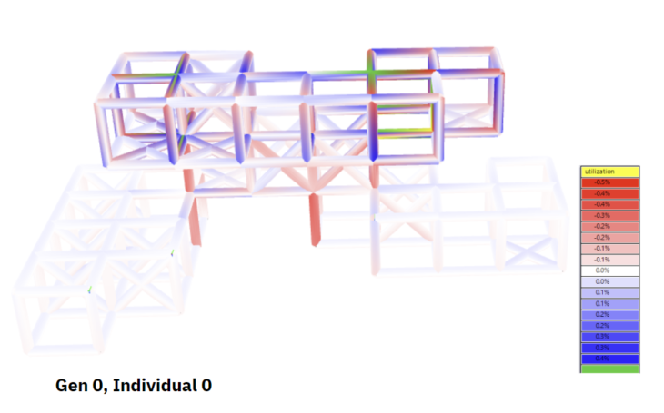
Figure 19 : Utilization (Gen 0)
We looked at 3 individuals from the total set, this is from generation 24 of 50.
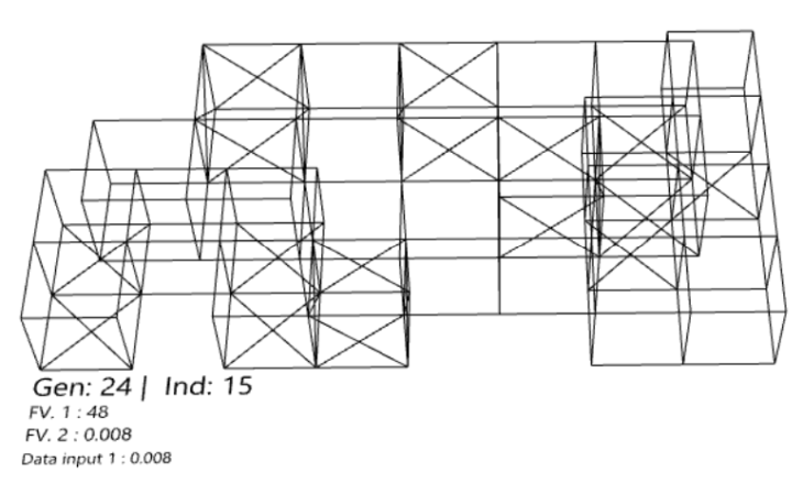
Figure 20 : Model geometry (Gen 24)
We can again see deformation at the cantilever, and displacement has reduced from the previous generation. We see that self weight has increased from the previous generation, and as would be expected utilization has also increased.

Figure 21 : Displacement (Gen 24)
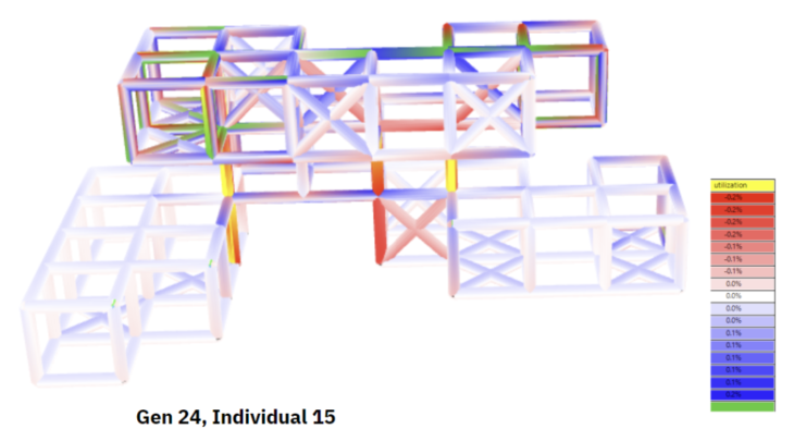
Figure 22 : Utilization (Gen 24)
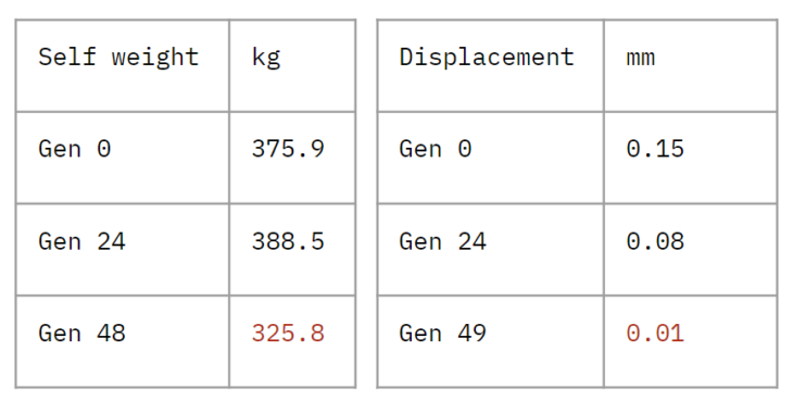
In the final generation, we find the lowest self weight, so the objective of minimizing material has been met.
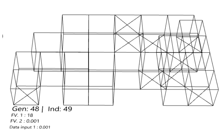
Figure 23 : Model geometry (Gen 48)
We also see the lowest deformation, a very small value. We see that the columns are the most utilized, given the transfer of vertical loading, as we would expect.
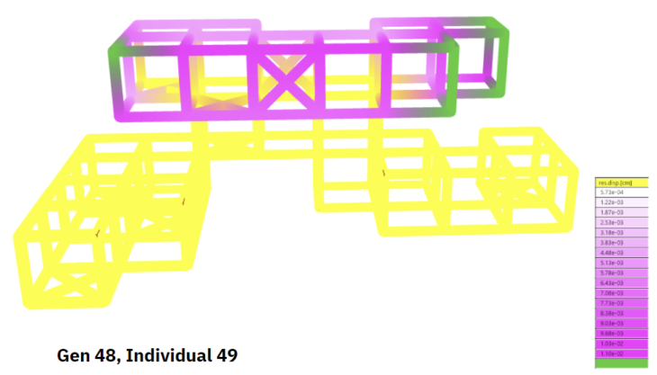
Figure 24 : Displacement (Gen 48)
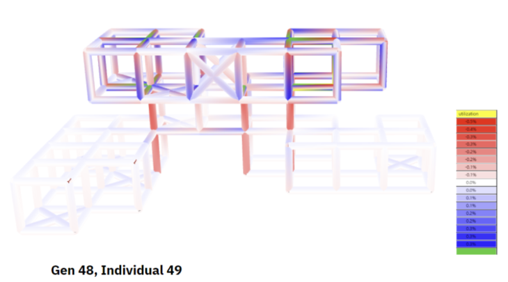
Figure 25 : Utilization (Gen 48)
We have found that the addition of bracing in the configuration suggested through this optimization study results in a reduction in materials and in deformation. If we decide to go ahead with bracing our cellular automata structure, this approach would be of use.
Conclusion
By reducing the displacement around the points with large displacement, it is possible to reinforce only the necessary points while using less material.
The next step is to consider the size of the beam members and appropriate reinforcement, which will allow us to propose a more optimized design in conjunction with the column study that was conducted.
Combining Karamba with Wallacei to consider appropriate bracing placement is a solid strategy to deal with the randomness that is cellular automata, and can lead to a reduction in materials and an increase in stability as the study has shown.
Structural optimization with Karamba was conducted with visualization, the results showed us improvement and drawbacks immediately.
DTSO Dharavi is a project of IAAC, Institute for Advanced Architecture of Catalonia developed in the Master In Advanced Computation For Architecture & Design 2021/22 by Students: Takeaki Sakakibara, Lucie Ketelsen, Naitik Sharma and Varun Mehta | Faculty: Manja van de Worp and Matthew Gabe