
DREAM BLANKETS
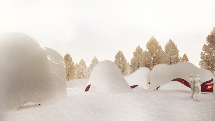
Winter landscapes, dreamy landscapes – an ethereal picture of black and white vastness pierced by yellow sun streaks through trees and mist rising from running waters. Ice sparkle in the sunlight adding to the dreamy allure of the season. In all of this ephemeral beauty, frigid temperatures lead many to curl up inside, leaving a quiet space for those willing to venture out and seek adventure within the city. Dream blankets operate as a space of activation, play and shelter within this serenity. They are a series of interactive warming huts that trigger a sense of warmth, intimacy, colours and play within a white landscape.
Located along a skating path on a frozen river, the design aimed to create a playable zone with structures that encourage visitors and passersby to move through and interact, seek warmth momentarily or lengthily while provoking ideas for play and placemaking. It also employs the ephemerality of the season in materialising the design. Frozen fabric becomes the sheltering medium during the winter, melting and allowing disassembly during the summer months.
The project explored parametric form-finding and optimisation strategies and workflows to create the structures. The process started off with a study of natural systems to extract parameters that would drive morphological, structural and perhaps experiential responses to the conditions and forces peculiar to the pavilion and context. We proceeded with a study of the site to understand contextual objectives and parameters and concluded with a series of steps and workflows for form generation and materialisation.
CONTEXT
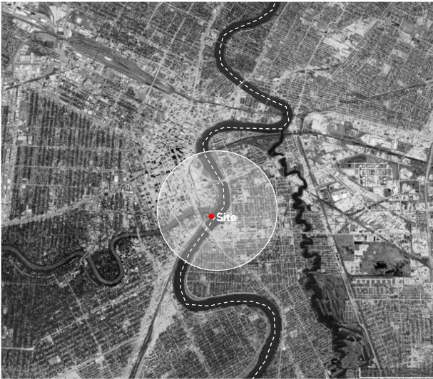
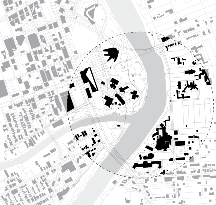
The pavilion will be situated along the skating trail on the Red River in Winnipeg, Manitoba, a city in Canada. In the winter, the Red River becomes frozen (about 1m layer of ice), providing a safe landscape for new activities. In this period, it is transformed into a skating trail along which many warming huts and sculptural parks spring up. The pavilion will be placed close to the Forks Market – a major hub along the river.
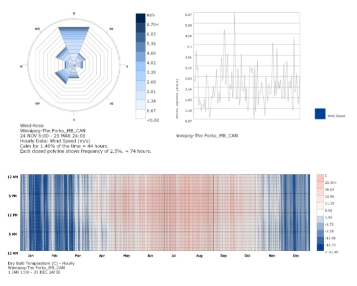
The environmental analysis of this context reviews that the prevalent wind direction from the north with windspeeds of above 6.7m/s running throughout the day. The temperature analysis shows that temperatures below 0 degrees (favourable for the sustenance of the pavilion) are seen from Late October to mid April. CFD analysis shows that wind speeds are high and surpass comfort limits. The whole section of the river is thus relevant as a project site.

NATURAL SYSTEMS STUDY
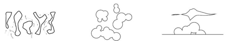
In this study, we examined soap bubbles and agent based pattern-formation as types of self -organising systems
- Soap films are made of entire (unbroken) smooth surfaces.
- The mean curvature of a portion of a soap film is everywhere constant at any point on the same piece of soap film.
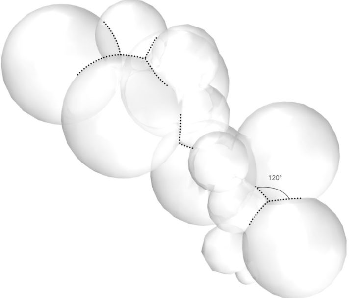
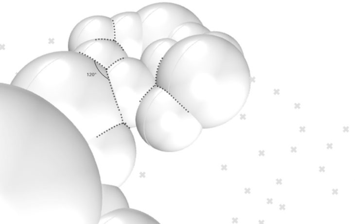
- Soap films always meet in threes along an edge called a Plateau border, and they do so at an angle of arccos(?1/2) = 120°.
- These Plateau borders meet in fours at a vertex, at the tetrahedral angle of arccos(?1/3) ? 109.47°.
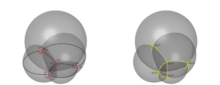
Soap Bubbles Showing Plateau’s third law and Plateau’s fourth law Source: wewantolearn.net
We also found that soap bubble configurations other than those of Plateau’s laws are unstable, and the film will quickly tend to rearrange itself to conform to these laws.

Bubble cluster stability. First image- stable cluster, second image – unstable cluster, third image – redistributed stable cluster
From Plateau’s Laws derives mathematical relations, through which bubble clusters can be created computationally. Since the angle of Plateau’s Border is 120° the following equation is true: D=sqrt((R*R)+(R*r)+(r*r)) where D – distance between 2 bubbles, R – radius of the first bubble, r – radius of the second bubble.

Illustration of derivation of mathematical formula from Plateau’s laws
COMPUTATIONAL DEVELOPMENT
Through the use of Anemone we have developed 2 workflows for creating bubble clusters.
WORKFLOW 01
This workflow starts with a point that is fed into the anemone loop. All parameters are generated within the loop and the final global geometry is extracted at the end.
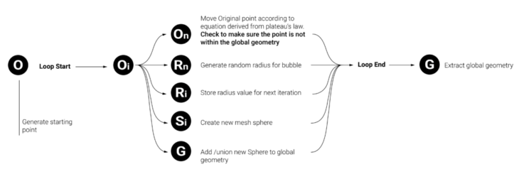
O – Starting point; Oi – Centre of first bubble; On – Centre of second bubble; Ri – Initial Radius (First Sphere); Rn – New Radius (Second Sphere); Sn – New Sphere; G – Global Geometry

WORKFLOW 02
This workflow uses a cloud of points, as centers of the created bubbles.
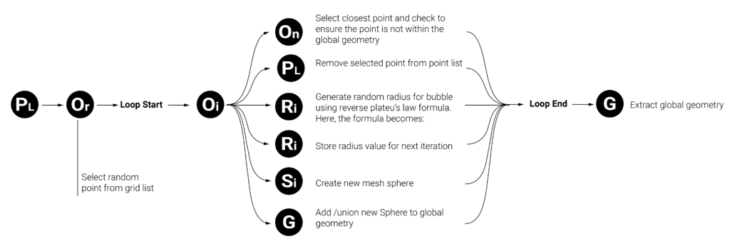
PL – Point cloud; Or – Random point chosen; Oi – Centre of first bubble; On – Centre of second bubble; Ri – Initial Radius (First Sphere); Rn – New Radius (Second Sphere); Sn – New Sphere; G – Global Geometry
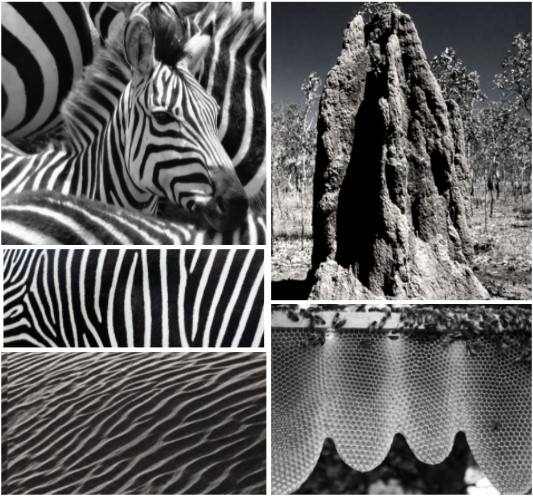
Mathematical theories, such as Turing’s Chemical Basis of Morphogenesis explains self organisation through reaction diffusion that leads to pattern formation in nature
We further investigated actions of agents in a self-organising system within the framework of reaction-diffusion theory. Our exploration gravitated towards the action & counter-action of agents that underlies reaction-diffusion, and less on mathematical formula interpretation in grasshopper and the resultant patterns it produces. In Turing’s reaction diffusion model, there is the activator agent (A) that autocatalyses and produces more of itself and also more of another agent (I). Agent I, also known as the inhibitor, reacts with agent A and suppresses the production of more agents A. This activator-inhibitor relationship can also be found in social insects such as termites and bees; these insects interact and create forms as a result of autocatalyctic positive feedback and inhibitory negative feedback combined with specific environmental features
COMPUTATIONAL DEVELOPMENT
Also through the use of Anemone, we developed 2 workflows for action and counter-action within a system.
WORKFLOW 01
This workflow uses a vector field to diffuse two agents (A and B) within a boundary. The two agents also react with each other to increase and reduce their quantities within the system. We created a voronoi base where the concentration of respective agents are calculated within each cell. The cells change colour as follows:
- Grey = Agent A > Agent B
- Black = Agent B > Agent A
Post anemone, we connected neighbouring similar-coloured cells using ‘proximity 2D’ resulting in a maze-like pattern we hoped to achieve.
 WORKFLOW 02
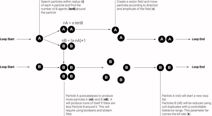
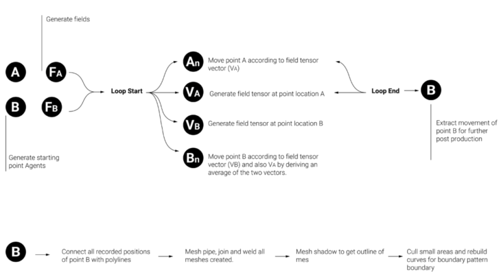
In this workflow, we employed a more direct interpretation of the activator-inhibitor system. We started with two sets of agents moving within different vector fields. One set of agents (A) activating the region, and the other set, (agent B), moving through and limiting the movements of agents A. We finished by mapping the paths of agents B to create a maze-like pattern.
- Agent A = Activator (Occuping space)
- Agent B = Inhibitor (passing through)
Post anemone, we connected the points from the anemone output; meshed the lines to generate mesh shadow lines resulting in varying maze-like patterns.

INSPIRATION AND INFLUENCES
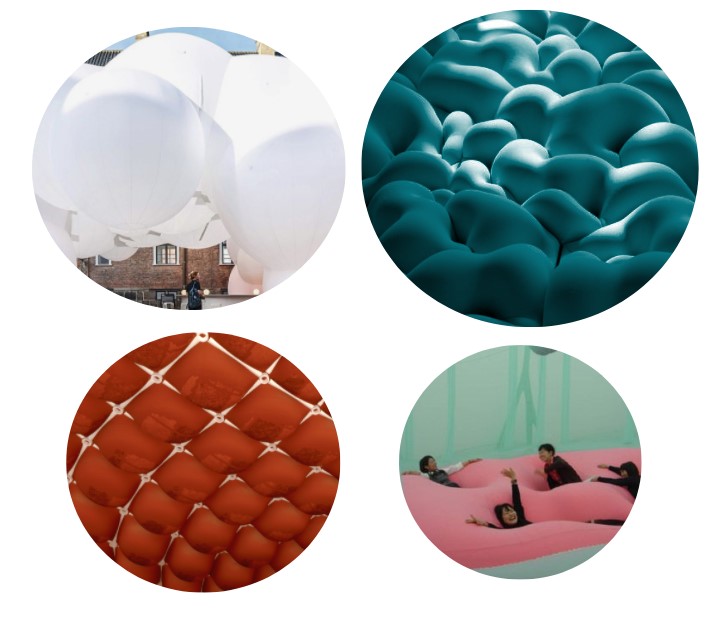
The warming huts competition has seen a number of vibrant entries constructed in the context since its inception in 2010. We drew inspiration from many of these huts constructed to attract visitors through their playfulness, where simple elements acquire different functions, and through their use of peculiar materials.
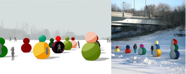
Weatherman W H by Jaimee Studios

Left – Nuzzles by Raw Design Inc; Right – The Hole Idea by Weiss Architecture
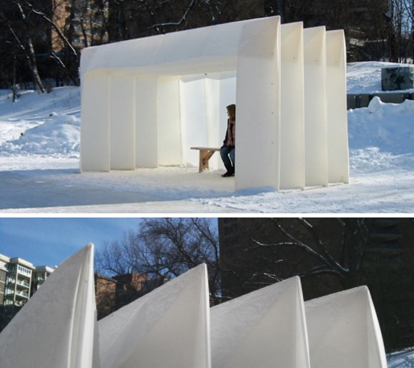
Corogami Hut by David Penner Architects
We also considered using ice as a material, considering the icy climate of Winnipeg and drawing conclusions of previous experiments made with it. In this example, the Pykrete Dome currently holds the record as the largest ice dome ever built, It is created by inflatable forms on which fiber-reinforced ice composite known as “pykrete” is sprayed.
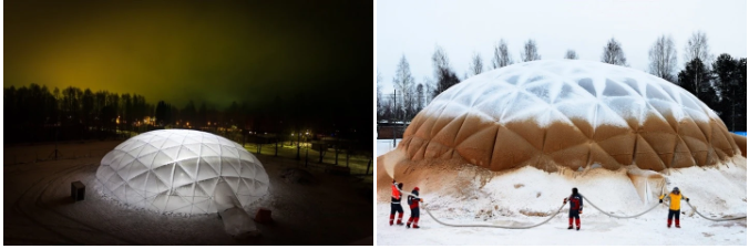
Pykrete Dome, Eindhoven University of Technology
PARAMETRIC DESIGN PROCESS
- Firstly, a maze-like spatial configuration is generated using the second computational workflow from the agent based systems, where visitors and skaters become activators and inhibitors.
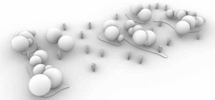
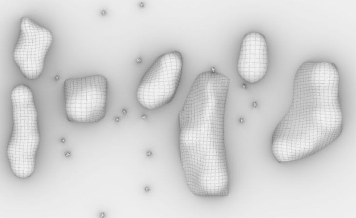
- Bubble clusters are generated using point cloud method. These bubbles are generated on the islands formed by the maze patterns and the serve as the base geometry for the next step.
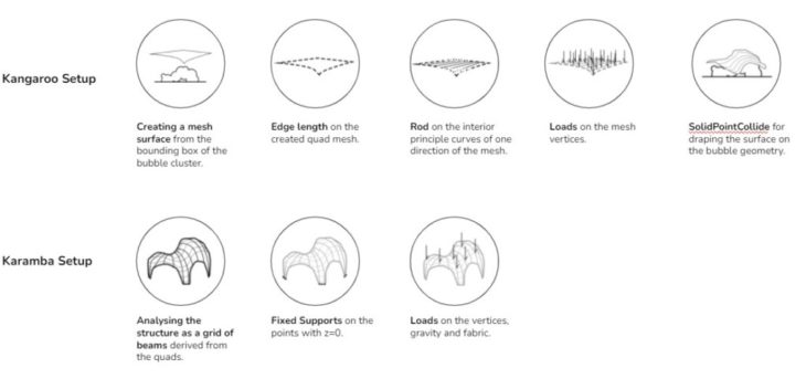
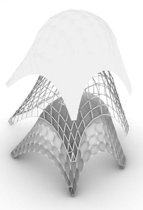
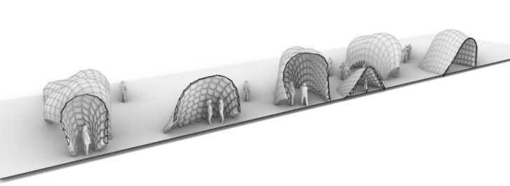
- Finally, mesh fabric surfaces are draped over the bubble geometry through Kangaroo to create a final structure.
Form-finding workflow
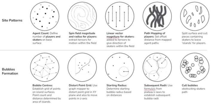
For the maze generation, two agents were identified from the context:
- Players = Agents A, circulating in random motion defined by a spin magnetic field, and activating the public space
- Skaters = Agents B, moving in a linear motion defined by a directional vector and limiting the action of the players
The paths of the skaters are mapped with an offset distance that establishes areas of potential collision on site. These areas are subtracted from the site to establish regions of play activities – islands -where the bubble geometries will cluster. For the bubble geometry, we established a grid of points on the islands. These points are distorted for a more dynamic output and the bubble workflow process deployed to generate clusters.
For illustrative purposes, the overall form-finding strategy was tested on a section of the river measuring 40m long x 20m wide. The design aimed to optimise the outcome of the maze generation for the following fitness values:
- Maximise: Island areas: 20% of the chosen site (170 sqm) and Bubbles/Circle Ground area: 2 sqm/person
- Minimise: No of Islands per region
Maze and Bubble generation workflow
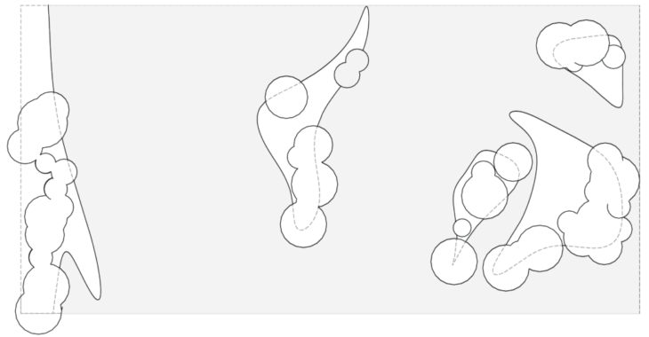
Maze and Bubble Plan on test site
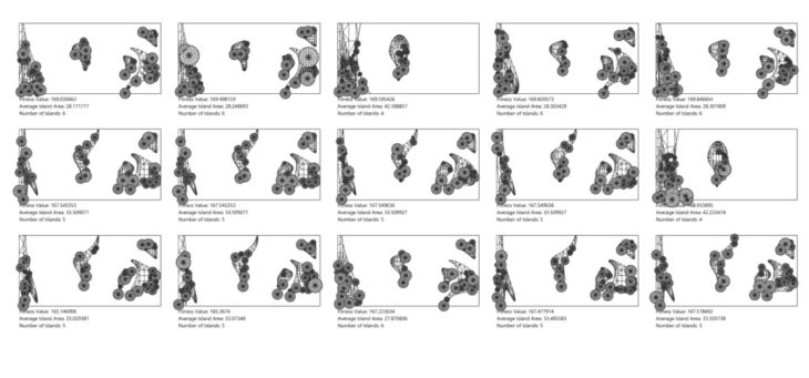
Maze and Bubble Cluster Optimisation
Maze and Bubble Cluster Overview
For the final pavilion geometry, we draped over the bubbles created on the islands to materialise the geometry. The following were critical parameters to ensure that the drapery covered the entirety of the spheres.
- Starting planar mesh: Scale factor and Mesh UV Values
- Kangaroo Edge lengths & Rods Components – Length factor, Zombie Solver – Number of iterations
In order to ensure that the structure was structurally stable, the geometry was run through structural optimisation process where the Galapagos evolutionary solver was used to generate and select geometries that minimised displacements and surface areas of the draped surface while maximising the average utilisation and areas for opening in the structure. To maximise in galapagos, we inverted figures by dividing by one before multiplying with other fitness values. This way, selecting minimising overall fitness values will have the opposite effect on the utilisation and opening goals. Final iteration selected was based on optimum headroom access vis-a-vis least displacement value.
Draping and Structural Optimisation workflow
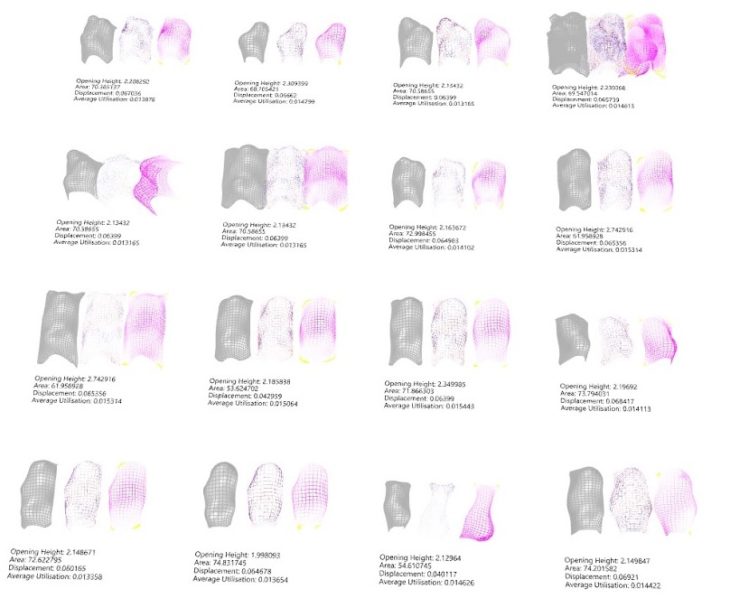
Structural Optimisation Matrix
Overall Draped Aerial View
Overall Site Plan
FABRICATION
Inspired by the Corogami hut, we considered using wet fabric as a material which would harden with time. The pavilion consists of three layers: Supporting steel structure , an outer skin ( wet rachel knitted fabric), and an inner skin ( colourful foam). A light gauge steel frame, defined by the quad cells of the surface mesh, serves as framework to support the wet rachel knitted fabric skin (durable enough) and also to hold the colourful interior foam. The beams are connected through circular joiners making connections at different angles possible,. The foams piece into one another and plug into the frame grid to create a dynamic and continuously changing structure in the landscape. Here, we played with a contrast of materials : strong – soft, white – colorful, cold-warm. The white and wetted outer fabric skin will freeze and become strong while the plush foam interior is soft, playful and leverages the insulating properties of foam to create a warm interior.
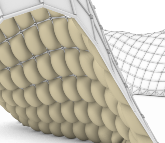
Materiality
PLACEMAKING
Warmth comes from being together; being able to gather in places to share stories and make new friends. The huts are warm and serene, the shapes are diverse, much like the people visiting. These huts offer a new type of public space: intimate for lone occupancy, open spaces for one-on-one or group conversations, play spaces to climb into and around, and soft surfaces to lean on, all the while experiencing warmth, and connecting with the delicate landscape.
Axonometric showing various scales of interiority
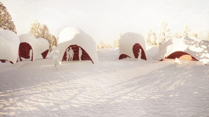
Exterior view
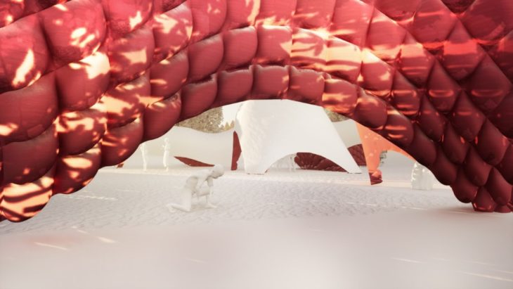
Interior view
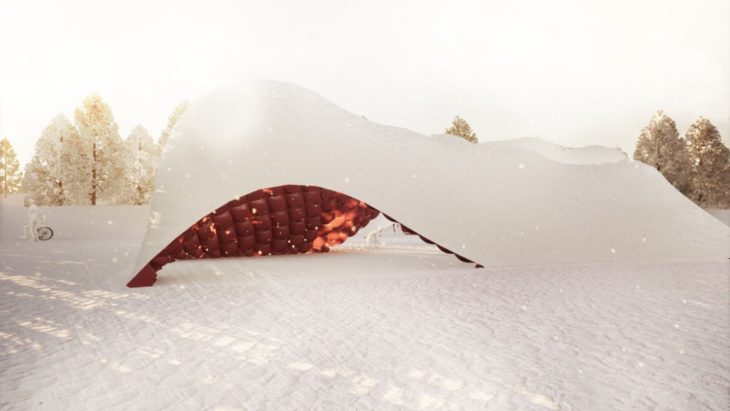
Exterior view
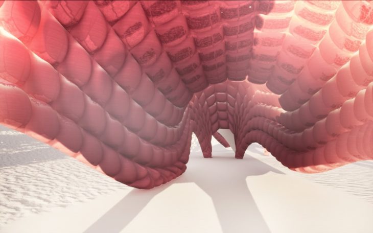
Interior view
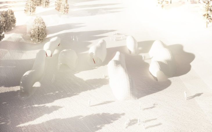
Aerial view
Dream Blankets is a project of IAAC, Institute for Advanced Architecture of Catalonia developed at
Masters in Advanced Computation for Architecture and Design (MaCAD) in 2021/2022 by students: Dami Akinniyi and Erida Bendo, and faculty: Rodrigo Aguirre and Hesham Shawqy (Assistant Faculty).