A drawing machine
I have a couple of ideas in mind that involve a drawing machine, so I wanted create one as a final project for our physical computing class. In post I’ll explain the technical side of the project. I’ll talk about my motivation for building such a thing in a later post. We just had a few days of time for completing this project, so I did my best of resisting the temptation to invent everything from scratch. I decided to base myself on the ‘hanging drawbot’ design, which to my knowledge was first done by Jürg Lehni with Hektor ten years ago. The basic idea is this: motors are used to control the position of a pen that is connected to the motors via threads. By using the Pythagorean theorem you can find out what the position of the pen is, and this information can be used to control the length of the threads. There have been countless variations on this theme in the meantime. I mostly used the work of Dan Royer and his DrawBot. I choose this project because it’s open source, simple and well-documented. I’ve used his project to show me the way, but along the way I’ve had some troubles and I’ve made a few changes. I’m documenting them here.
Bill of materials
I almost couldn’t start this project because I couldn’t get some materials in time. Then I found out about Barcelona Cybernetics, where you can order Arduino’s and related components online and pick them up the same day. Here’s what I bought from them:
- 1 x ADA-081 Adafruit Motor/Stepper/Servo Shield para Arduino kit – v1.0, €24.81
- 2 x ADA-324 Stepper motor – 200 steps/rev, 12V 350mA, €32.10 for 2
- 1 x A-0072 Arduino ETH Shield Rev3 SIN PoE, €35.10
Then I went to Onda Radio where I go a couple of smaller standard items:
- A power supply (12v, 4.7 amps, around 20 euro)
- Cabe for power supply (2.80 euro)
- Wire, in 4 colours: red, yellow, green, grey, the same colors as the ones on the motors. (2 euro per color) The wires on my motors were pretty short.
- Some screw terminals for extending the wires of the motors.
And this is what I picked up in a basic crafts shop:
- A Staedtler marker.
- A bulldog clip. (Used to give the pen holder some weight, could be something else.)
- Fishing line.
And this I had already:
- An Arduino Uno
- Scrap pieces of plywood and acrylic.
- A big wooden board to mount everything on.
- Some M3 screws in various sizes.
h2. The motorshield I checked out various ways to control the stepper motors. The easiest seem to be EasyDriver and Adafruit’s shield. I went for the shield, since it’s only slightly more expensive but you can control 2 motors with it. You need to assemble it. I didn’t have much soldering experience, but it was pretty easy using the instructions. It took me around an hour.
The motors
Dan sells his DrawBot in kit form, and this comes with motors that can do 400 steps per rotation (see
https://www.sparkfun.com/products/10846,
more or less same price). This type of motors are used by CNC machines, so there pretty accurate. I’m using the steppers sold by Adafruit, which can only do 200 steps per rev. That means there’s only half as precise. In pratice, the results I get don’t seem that bad, but I’m curious what the difference is. The wiring for the motors is explained on Adafruit’s product page:  After this I downloaded the library for the shield and I ran the examples. Everything seemd to work fine. The wires on the motors were short (around 20 cm) so I extended them by connecting them to 1m wires I cut and tinned. I used screw terminals because I wasn’t sure if I was going to keep the motors in this setup. It was a good idea to spend a few euros on getting wires in the same color. This made this job much easier.
 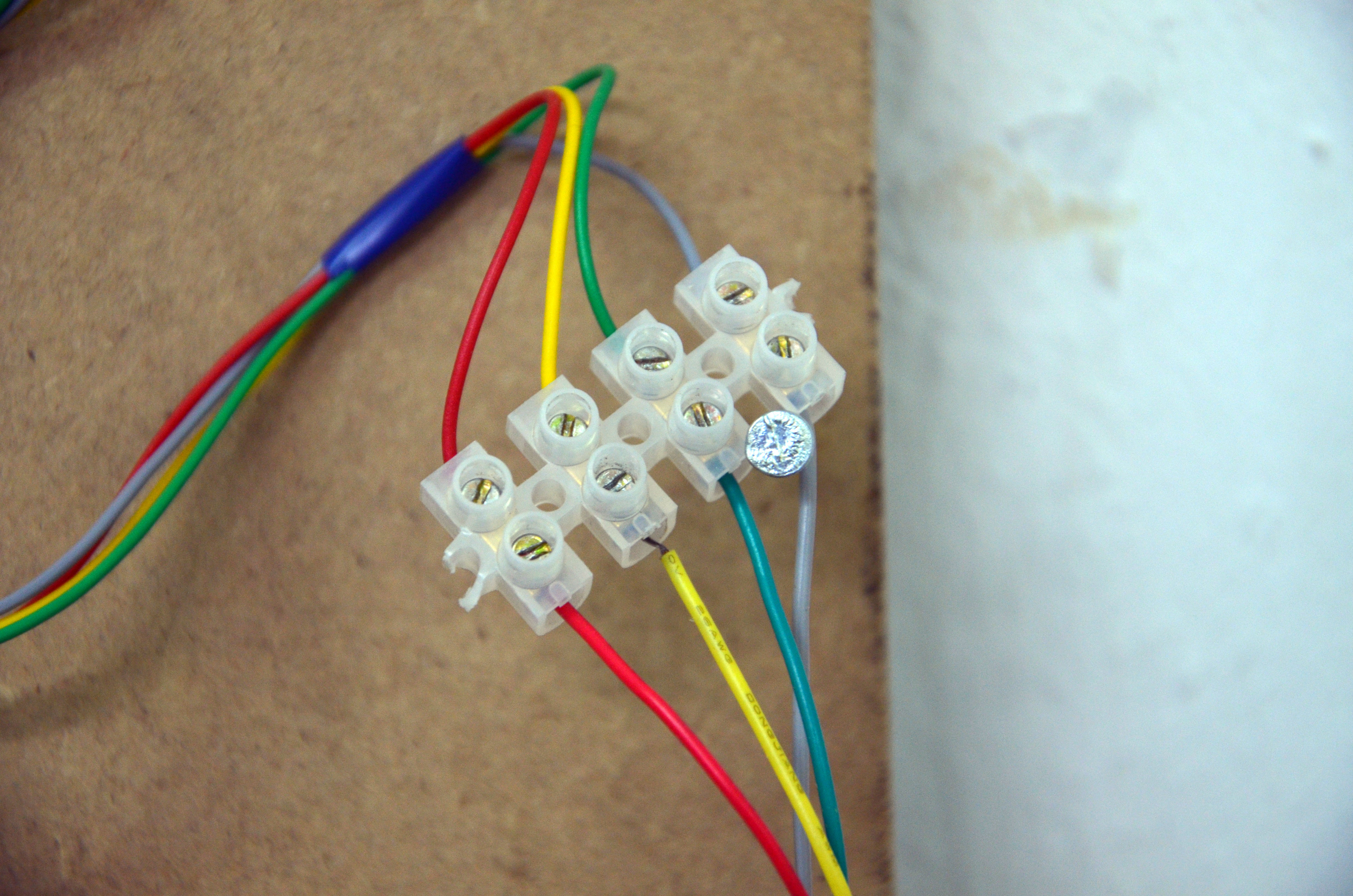 The motors need 12V and 350mA each. I got a 12V/4amp power supply in the form of those metal boxes. You need to buy a power cord seperately for these things.
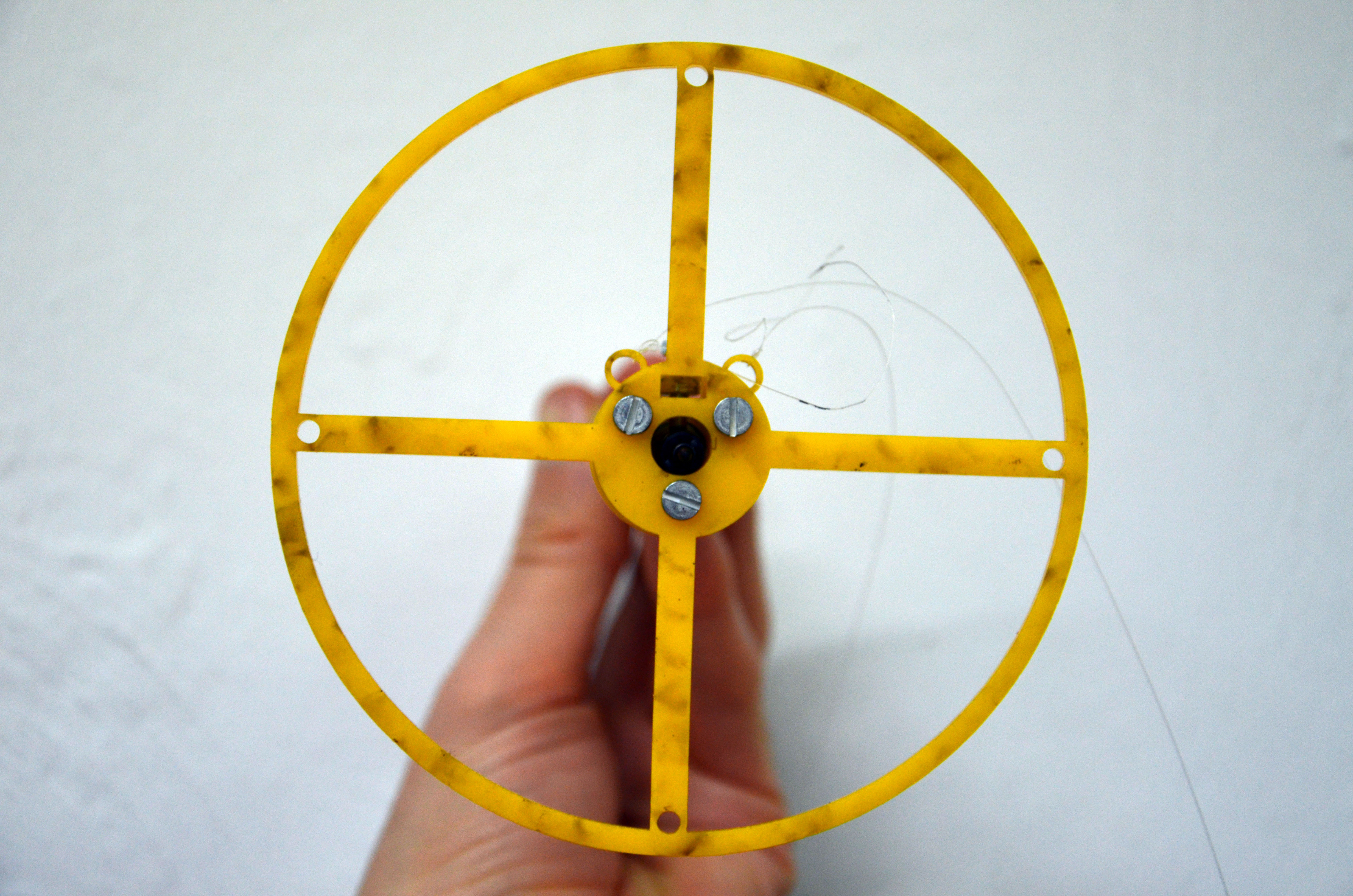
Motor mounts
You’ll some way to hang the motors on a wall or a board. Dan’s 3D-printable design for the mounts is nice: it functions as an L bracket, and it has holes for the thread. I adapted it for laser cutting by tracing it in Rhino and adding some notches so the parts could be glued. Here is what I sent to the laser cutter: 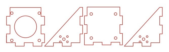 I used 3 mm acrylic. Here is the mount after glueing:
 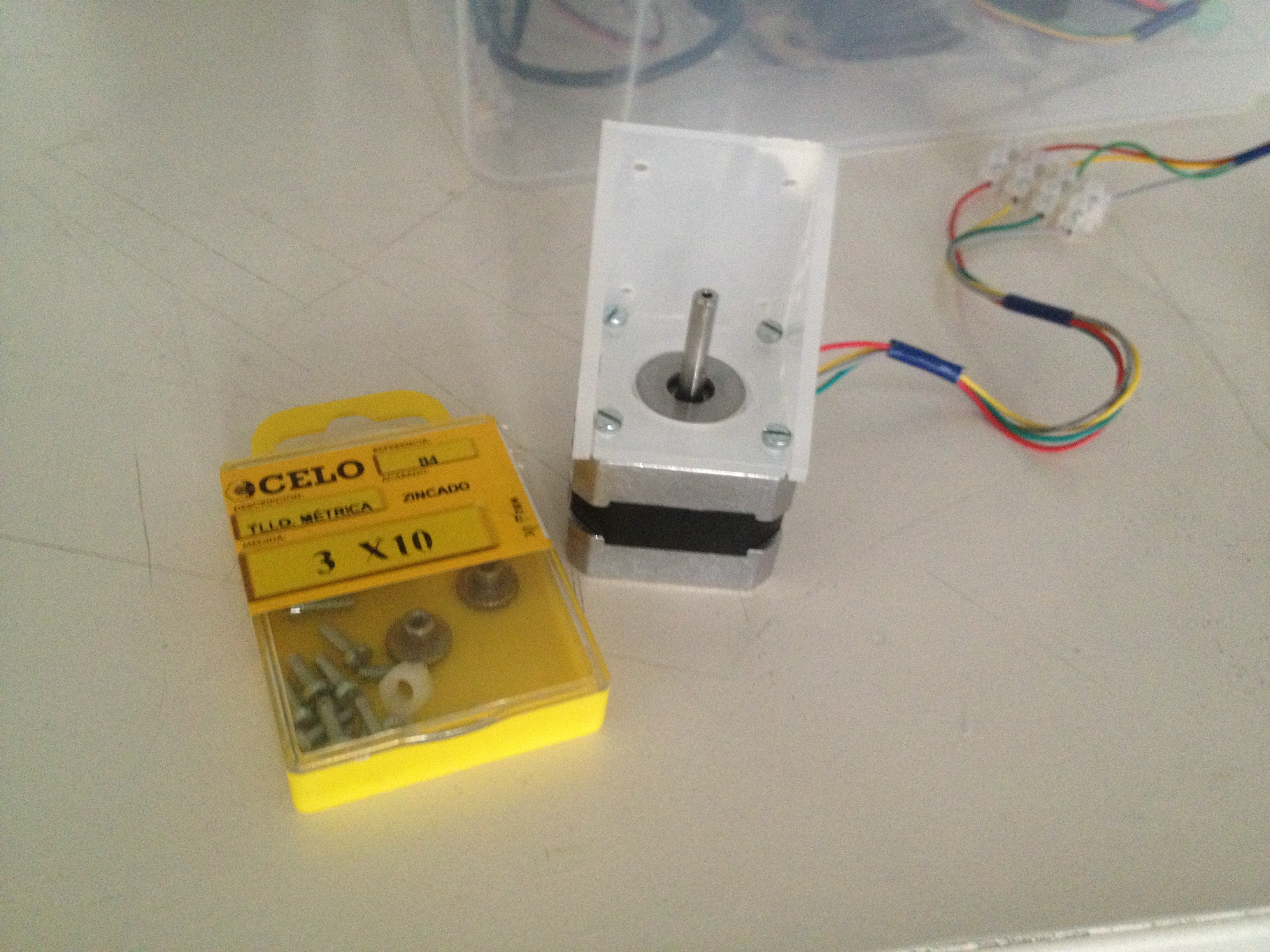 I forked Dan’s project on GitHub and added the files in AI, PDF and Rhino format.
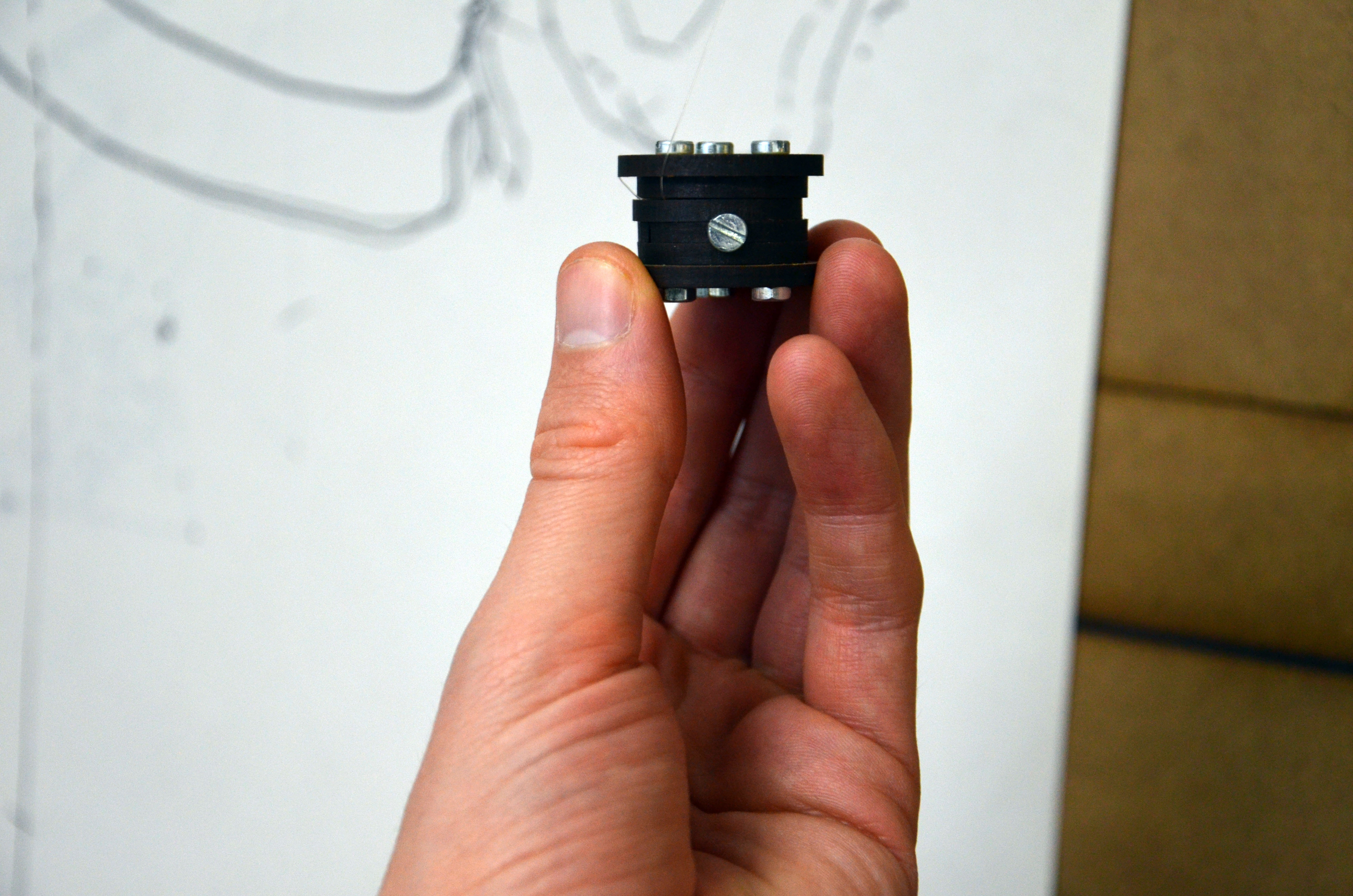
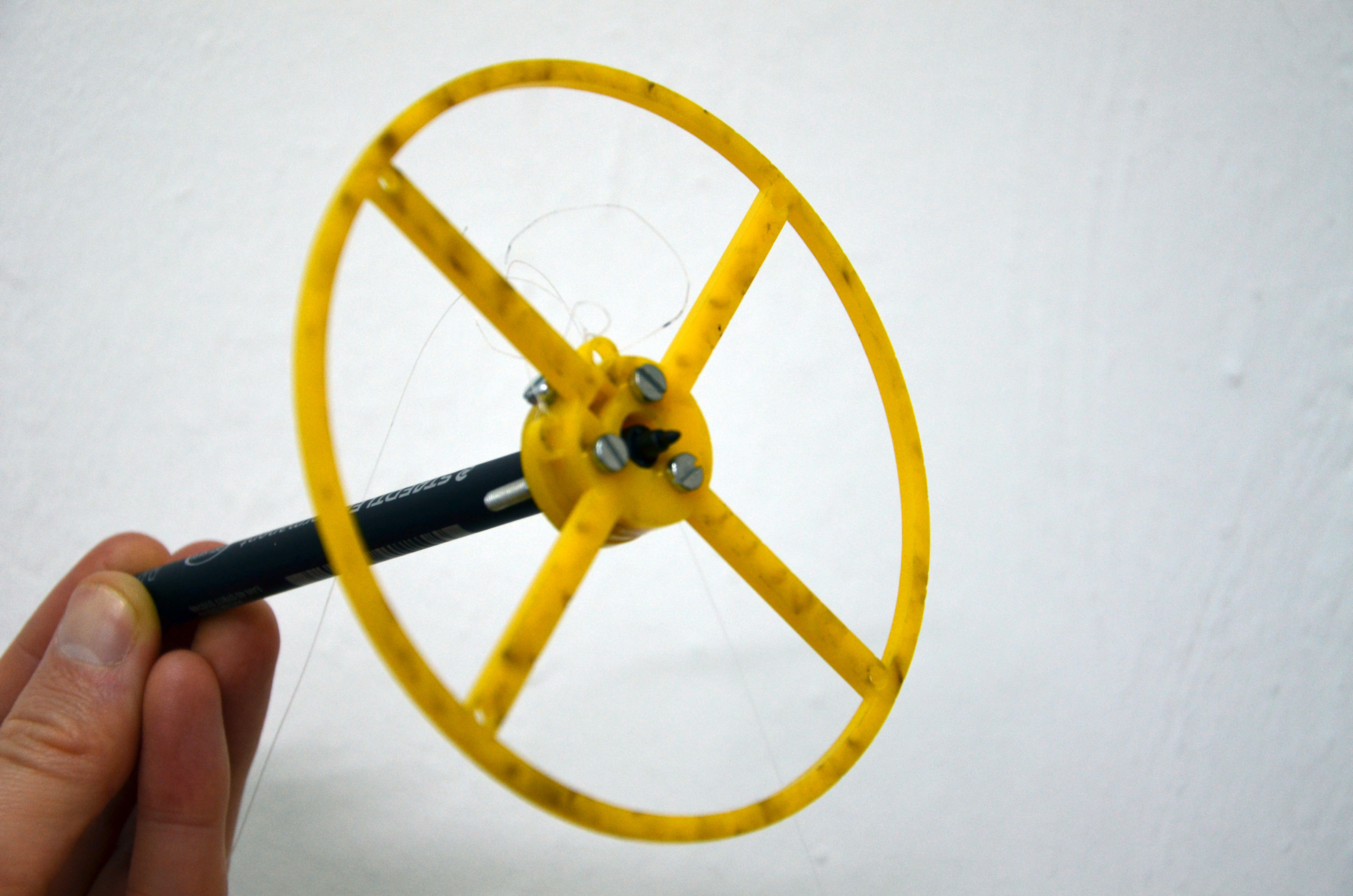
Spools
I really like this bobbin design from Stuart Childs. It can be laser cut, and it has a hole for a screw that can be used to tigthen the spool to the motor. Stuart’s bobbins are too big for the motor mounts I used, so I made a variation on it: 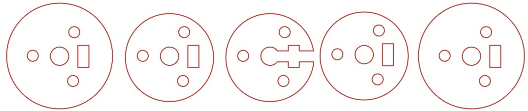 I cut this on 3mm plywood. I’m using fishing line for the thread, and I connected it a screw after to the second disc. This is how the whole thing looks when it’s assembled:
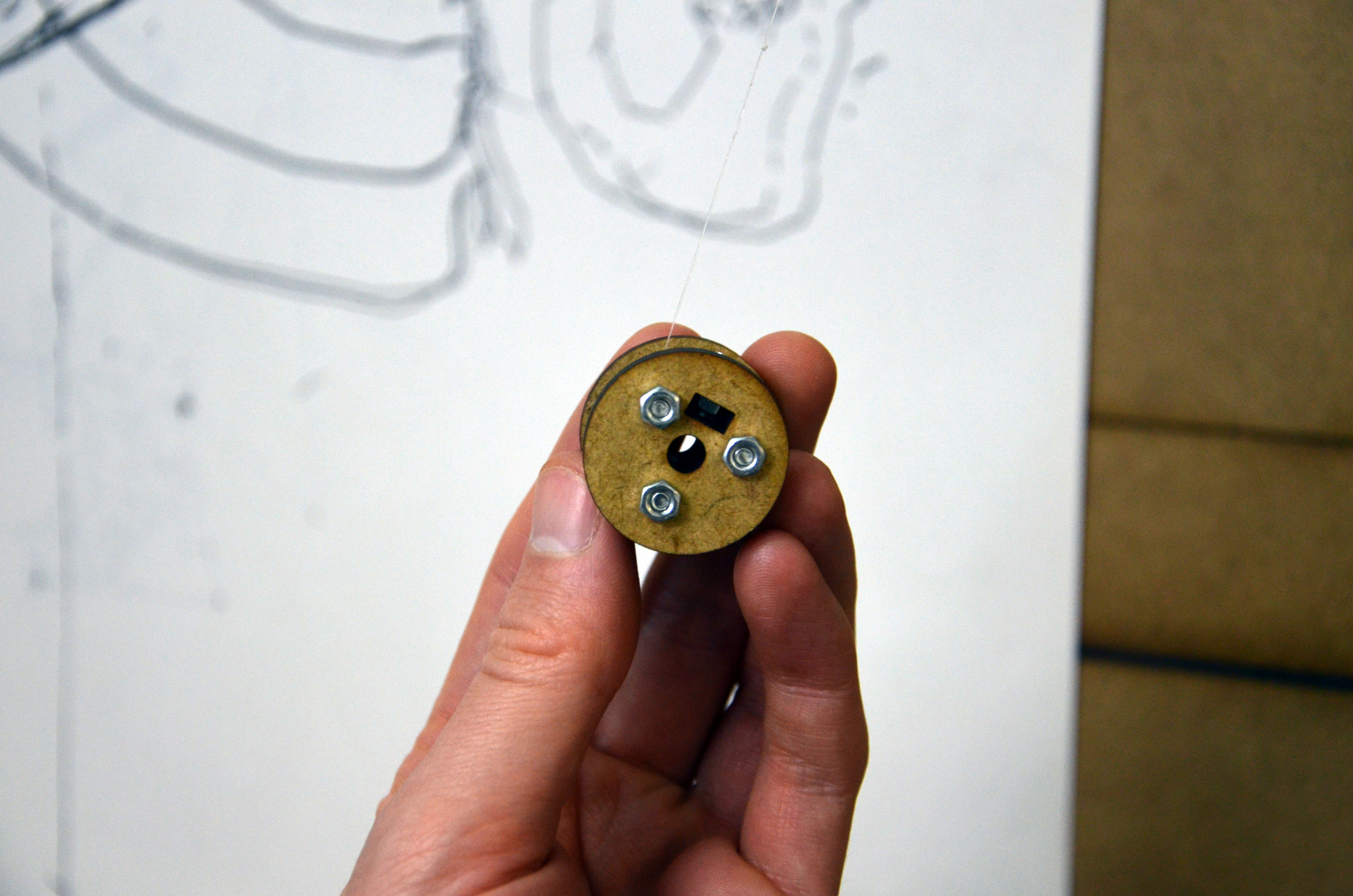
 The “files for lasercutting can be found on GitHub.
Pen holder
I reused the same idea of the tightening screw for the pen holder. This is the file that was sent to the laser cutter: 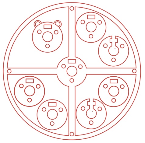 This was cut on 3mm acrylic. Here is the finished piece:
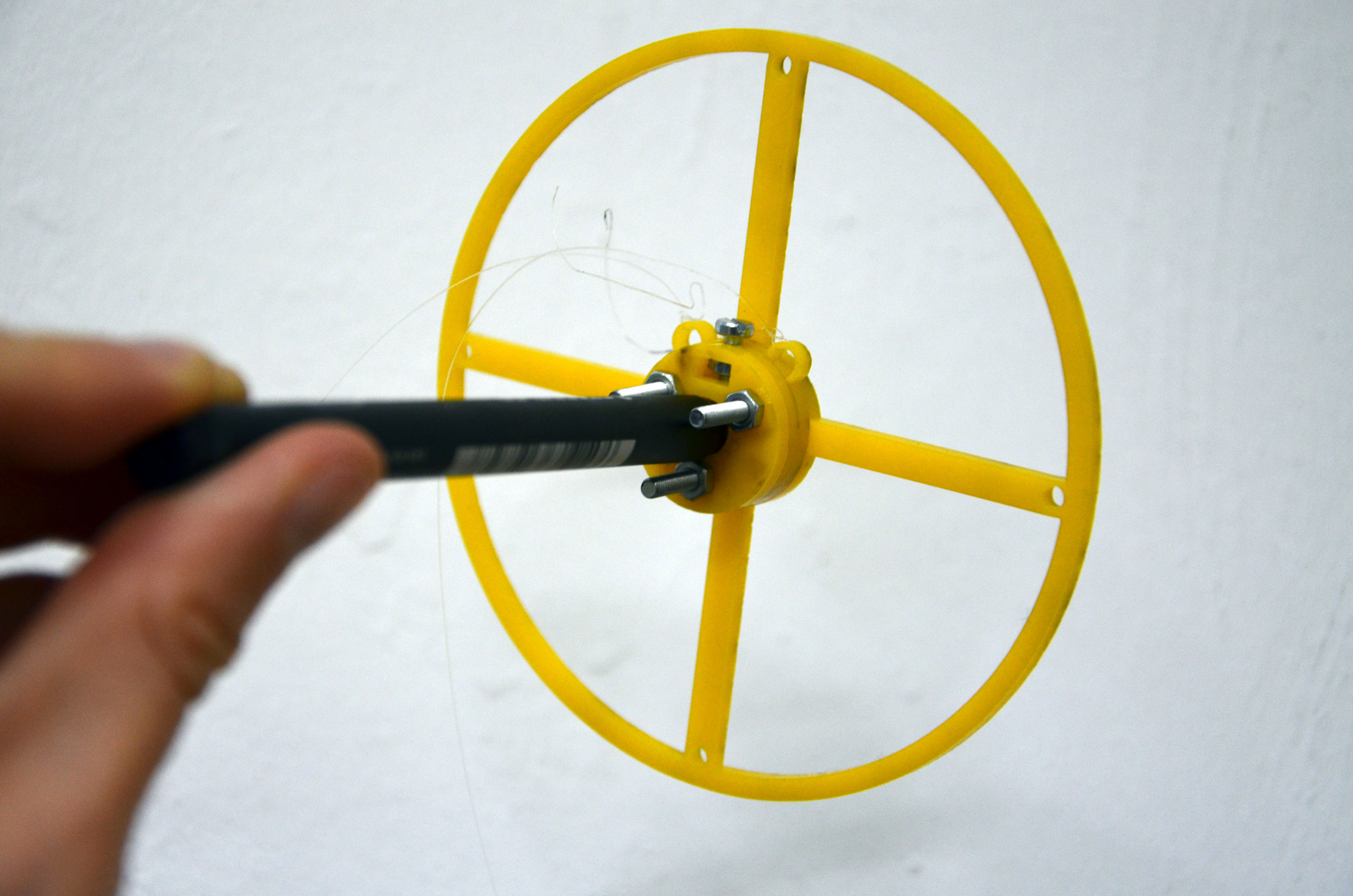
 The hole in middle is big enough for the tip of a Staedtler marker. I had to add a bulldog clip on the top to add some extra weight so the pen holder would be close enough to the board.
Firmware
I loaded Dan’s DrawBot firmware into my Arduino. There’s a couple of very important changes I made:
- Bobbin size was set to 3mm.
- And, most importantly: the maximum speed of the motors was decreased from 2000 RPM to 250 RPM. It took me a while to understand that this was necessary. With the 2000 RPM setting, the motors couldn’t keep up. They went a little forward, and then back again.
See the changeset on Github for the exact code.
Drawing
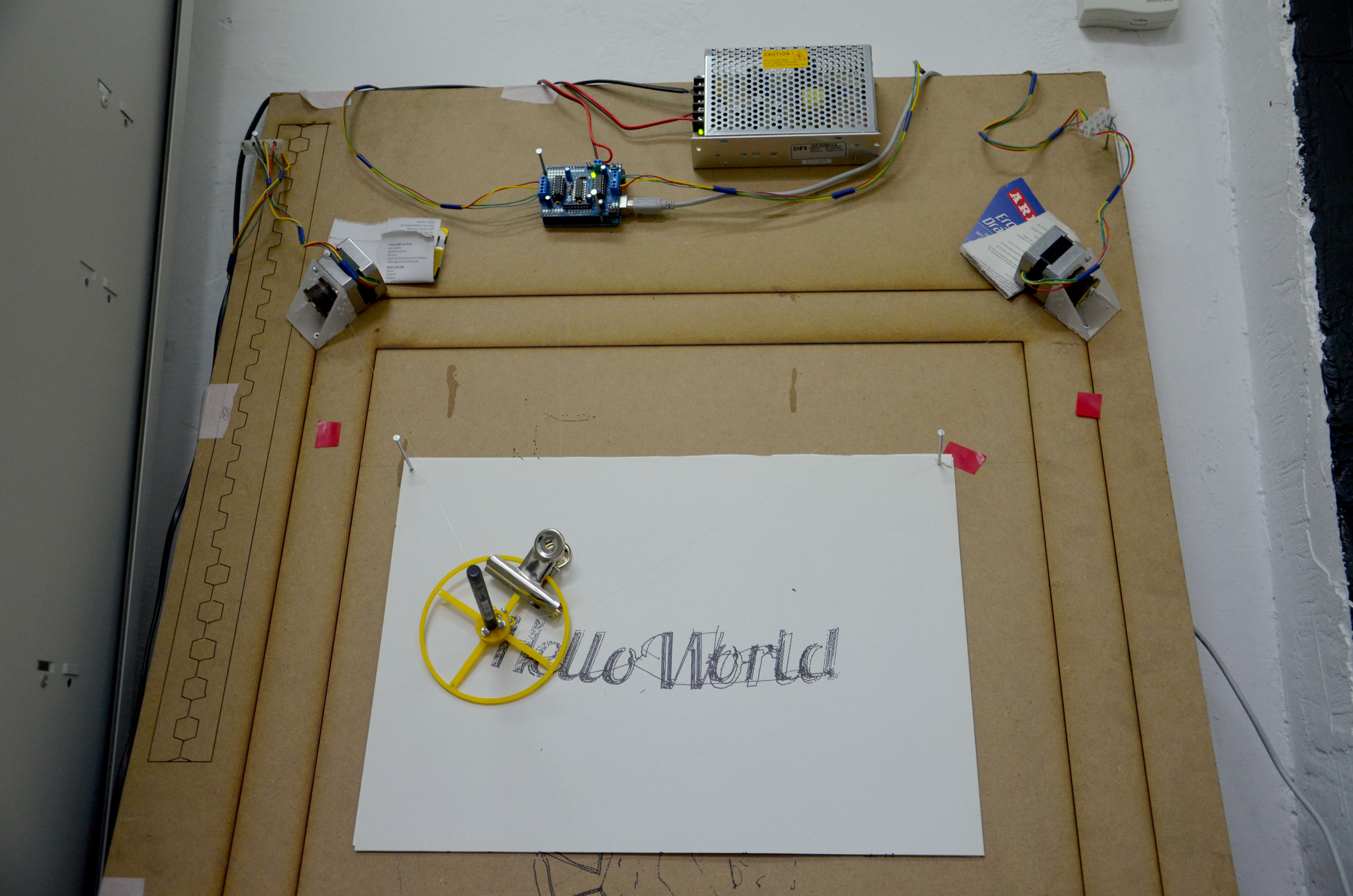
Dan’s DrawBot project includes a handy interface for controlling the drawing machine and sending images to it. This is how mine has to be configured: 
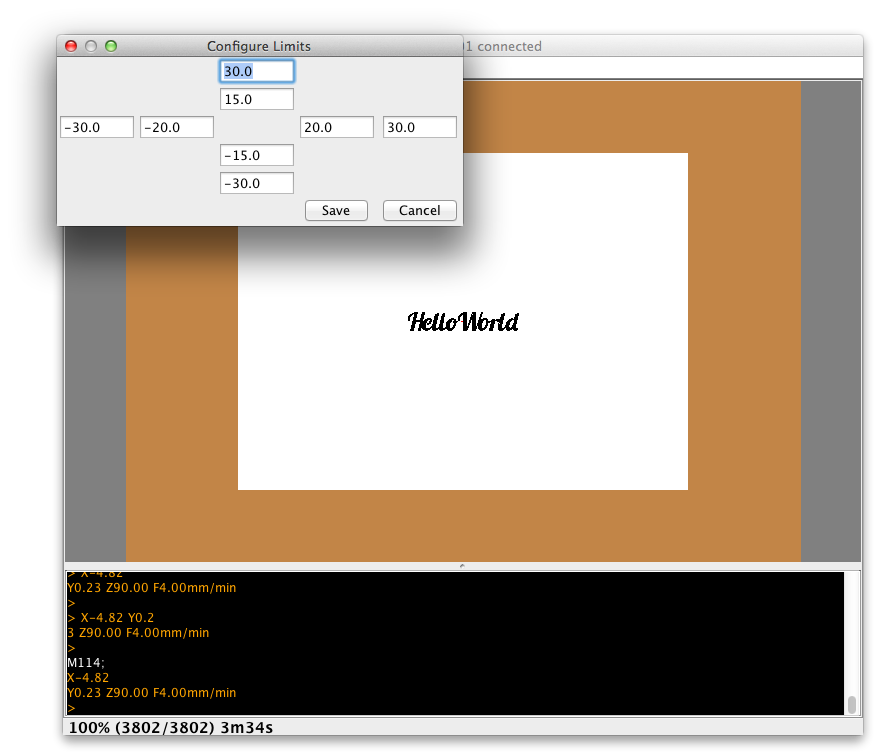 Here’s how the first test looked like: