Overview
The project began with a vision to explore and fabricate a tool that can work in tandem with the robotic arm to create complex patterns on surfaces both two dimensional and three dimensional.
Study
Examining pattern forming such as block printing, hammer forming and carving on varied surfaces, we narrowed down our research to pattern forming on metal and clay. Both the materials have huge industrial applications in the field of architecture and construction hence, encouraging us to envision a project that is more in tune with the industry and practical application.
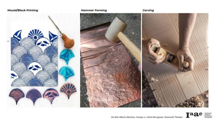 During the course of our study we figured that the technique of repeated pounding of a surface works well for both metal and clay. Taking this idea forward we designed a prototype with a piston that can ram into the material and create impressions.
End Effector
Generation 01
The prototype demonstrated simple mechanism of converting rotary motion to linear. The prototype is powered by a DC motor to deliver maximum power and rotations per minute.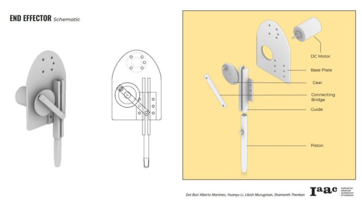
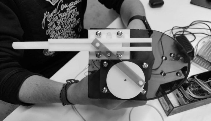 The generation 01 prototype was a good learning curve. We figured out angled bridge connecting gear to the piston is not an inefficient way of translating the motion as much of the power is lost. The piston was 3d printed to be a square piston which again did not help in smooth transition of movement.
Generation 02
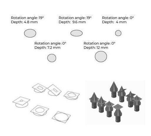
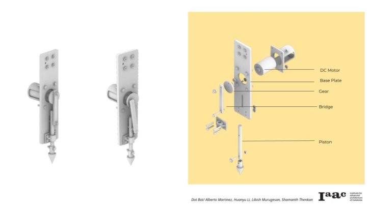 In the second version of the prototype the piston was placed right below the gear. This helped in reducing friction, vibration and also loss of power during the translation of motion. We equipped the piston with detachable tips/end caps to get different patterns. Flexible tips also aide in dealing with different materials as they can be changed without altering the end effector set up.
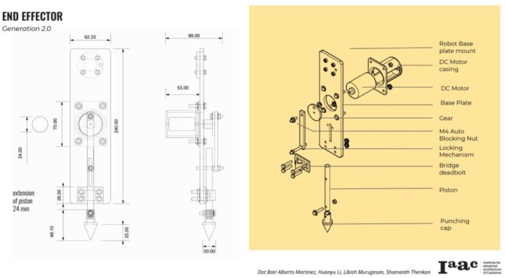
Electronics Schematic
The DC motor of the end effector is controlled through python code that is fed into the pico board. A digital channel is established between the robotic arm and the pico through the optocoupler. A relay module of 3.3v connection is used to send signals to the DC motor.
System Schematics
Pico Board to DC motor Schematic
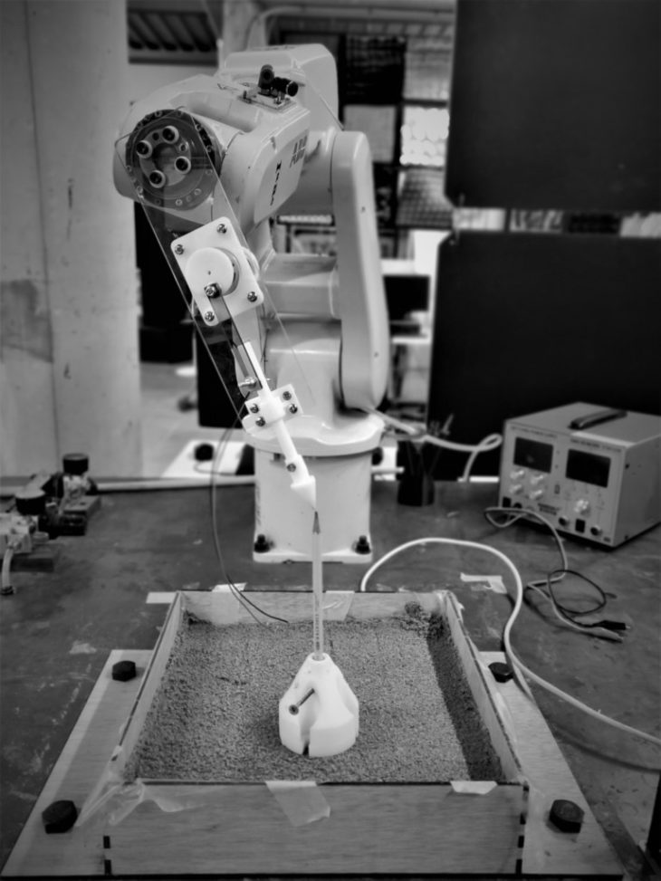
Robotic Process
The system configuration relied on two key parameters, the speed of the robot and the speed of the end effector. Although there were other factors that influence the pattern design, speed is key in controlling the resolution of the pattern. Multiple tests were conducted to determine optimal set up for the system deliver desired results.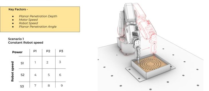
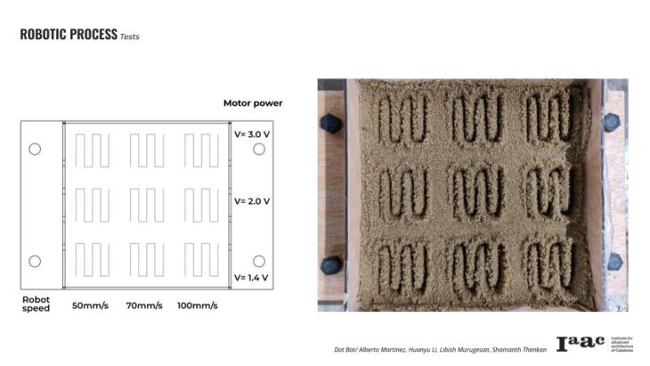
Tests
Test 01
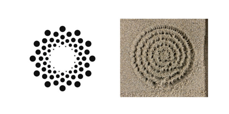
Motor voltage – 2V | Robot Speed – 50%
Test 02
Motor voltage – 1.4V | Robot Speed – 50%
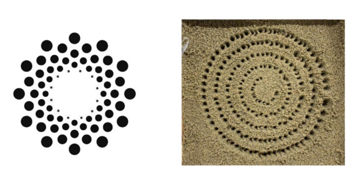
Test 02 configuration worked the best to attain desired result.
Industrial Application
Immediate industrial application that we foresee is in the tile and metal workshops for custom products. Metal sheets can be deformed and patterned on by repeated hammering on the surface.
By using clay as a material medium large scale custom tile patterns can be fabricated by breaking down the big picture into smaller tile blocks. The Dot Bot avoids the tedious and expensive process of creating unique mold for each custom piece of the tile. This technology can be scaled to any size as the big picture can always be broken down into smaller units. Smaller units work out better logistically as well.
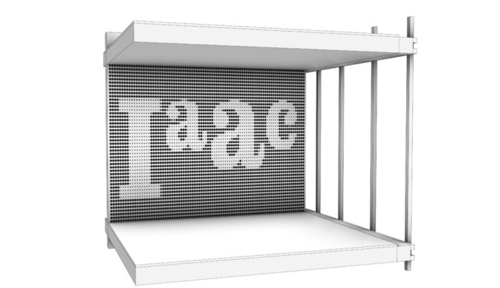
The big picture...
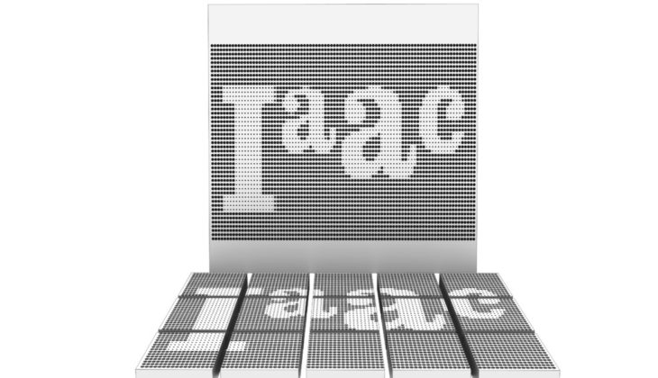
The big picture broken into smaller tile units that can be assembled on site.
Dot Bot // Hardware I is a project of IAAC, Institute for Advanced Architecture of Catalonia developed at the Master in Robotics and Advanced Construction in 2021/2022 by:
Students: Alberto Martinez, Huanyu Li, Libish Murugesan, Shamanth Thenkan
Faculty: Angel Muñoz
Faculty Assistant: Shahar Abelson