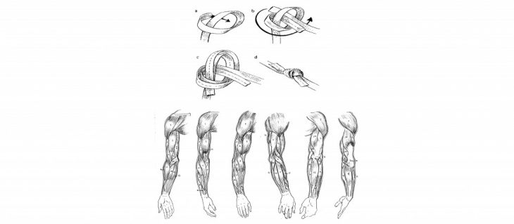
Reference of ligaments, highlighting the arms primary and secondary “structure” between the bones and the ligaments.
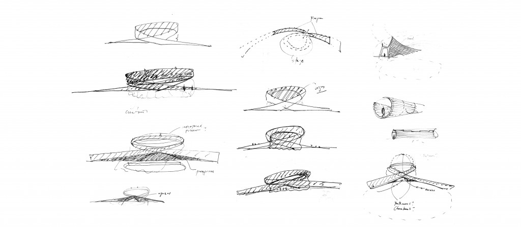
Preliminary sketches drawn when developing the overall form of the pedestrian bridge as it ties around the stage.
Sketches exploring the potential connections to be made between the primary structure of the bridge and their connection to the ground plane.
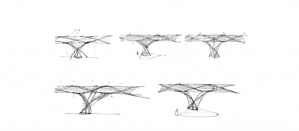
Explorations of structural systems to be employed for the bridge.
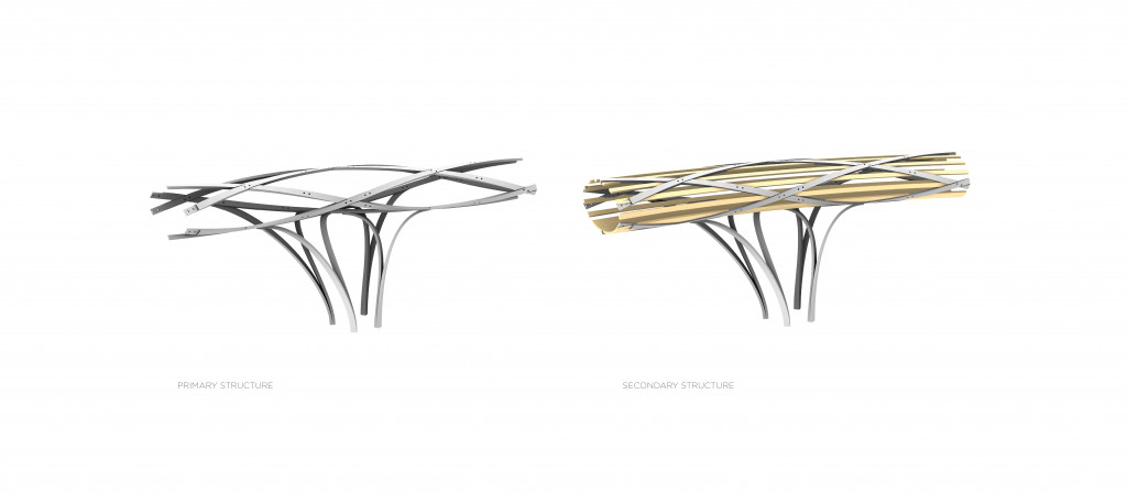
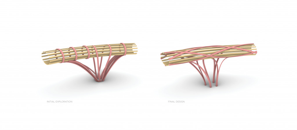
Diagram dissecting the two structural systems taking place. In grey, the primary structure is isolated. It is comprised of the columns and the spiraling elements that nest the secondary shown in yellow.
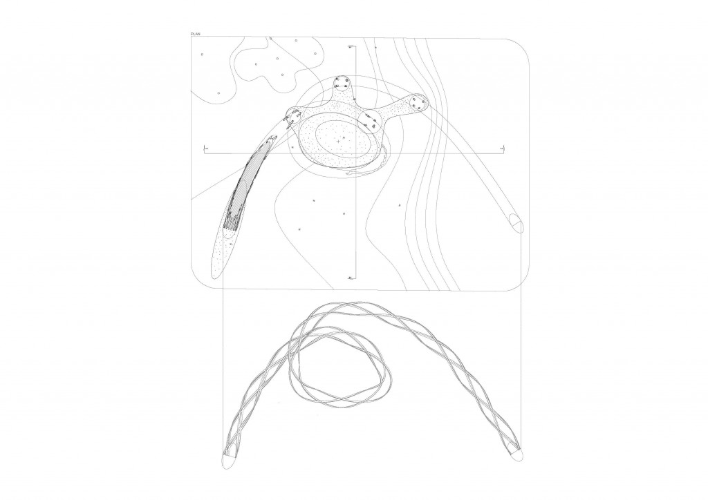
Plan highlighting the relationship between the topology, the bridge and the stage. At the bottom is the isolated primary structure.
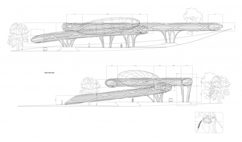
Sectional Drawings.
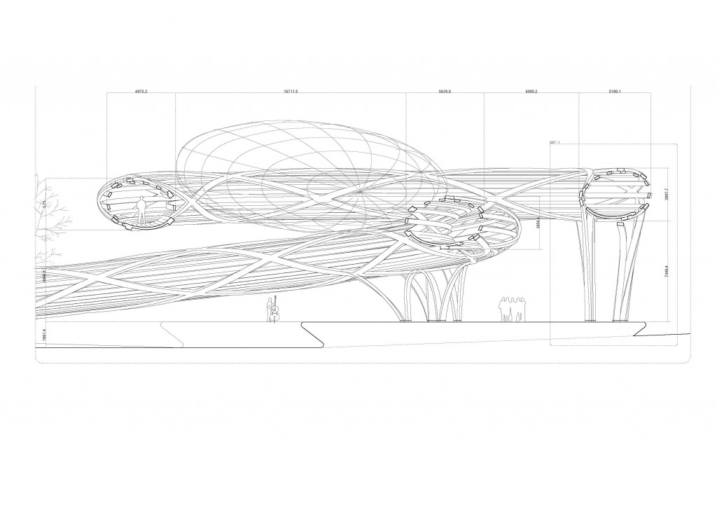
Close up of the section.
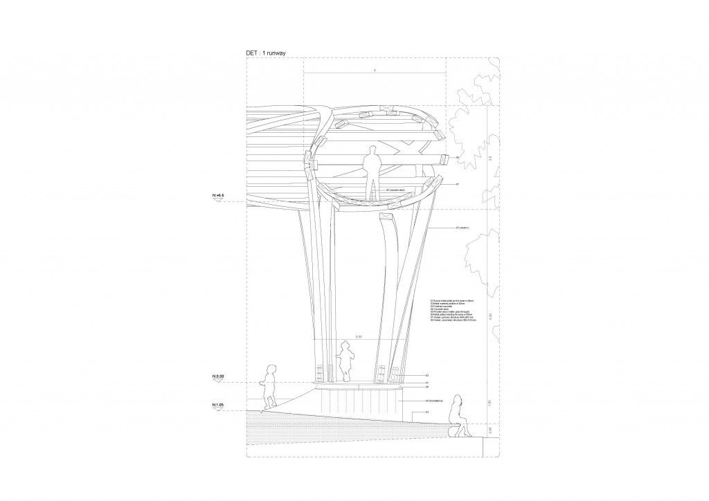
Detailed Section.
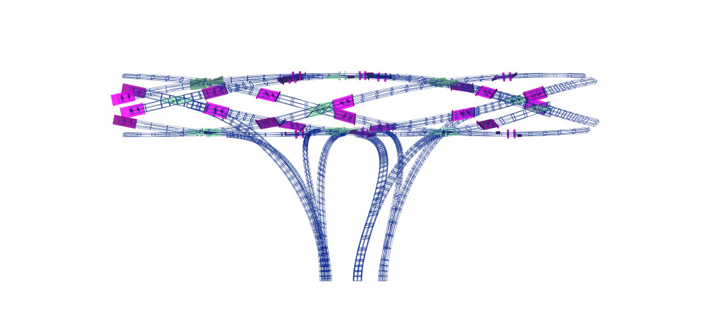
Diagram highlighting the connections and cuts made to the primary structure. In purple, the scarf joints separate the elements lengthwise and in turquoise cross-lap joints illustrate where the elements intersect.
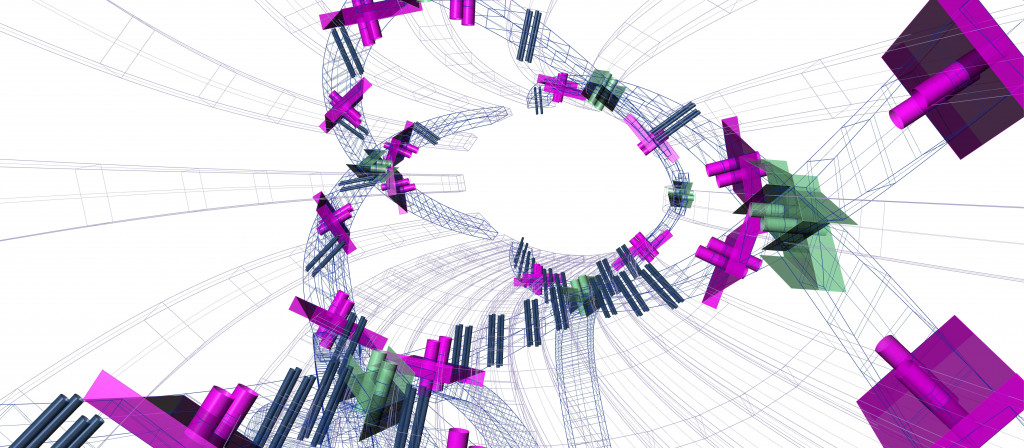
Close-up view from the interior of the bridge of all connections between the primary and secondary structure.
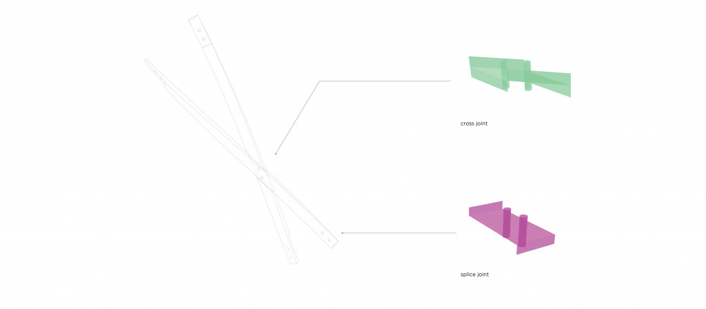
Diagram isolating two elements linking the two types of connections / cuts.
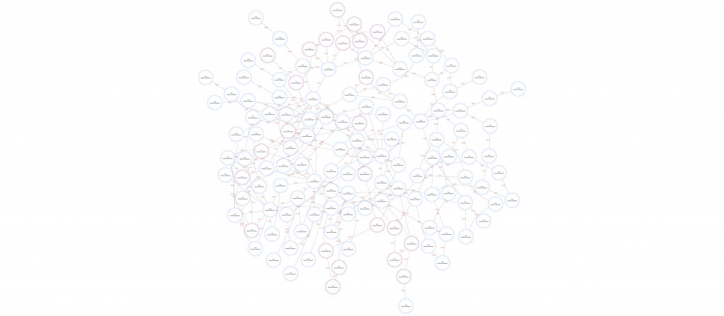
This diagram uses a portion of the bridge, 1/9th to be precise in which we find 134 elements. Each circle represents a singular glulam elements and each line is the type of connection made between elements. This diagram serves as a overall view for manufacturing and construction showcasing the types of connections and the way each elements is to be bent (straight, single curve or double curved).
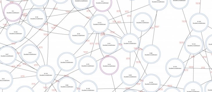
Close-up of of map shown above.
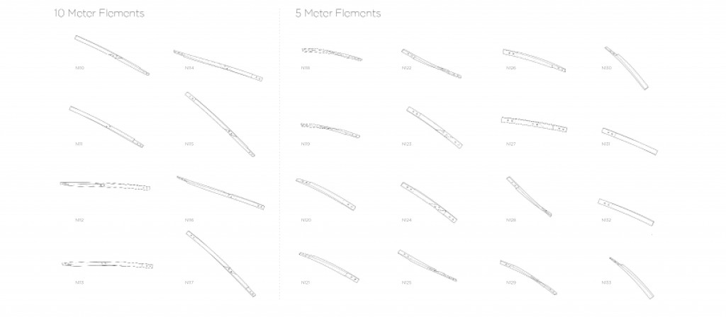
Shopping list of elements that are used to make up the primary structure for 1/9th of the structure. The elements are separated by lengths due to intersection interferences and therefor some had to be longer.
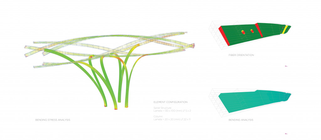
The diagrams illustrate the curvature of each glulam elements, green meaning bending is at a minimum and red bring the maximum curvature from each element. The primary structure is made-up of glulams composed of lamelas that measure 130 x 100 (mm) and there are 5 x 2. The columns on the other hand due to high degrees of curvature have lamellas which measure 20 x 20 (mm) and there are 22×11. On the right-hand side, at the top is a diagram which shows fiber direction in relation to where the element is cut. Red showing perpendicular cuts to the wood fiber and green meaning the cuts are parallel. The light gray outline shows the lamellas which make up the glulam element. At the bottom is a diagram illustrating fiber direction change, in the case the change is minimal but the gradient shows the bending moment in the element.
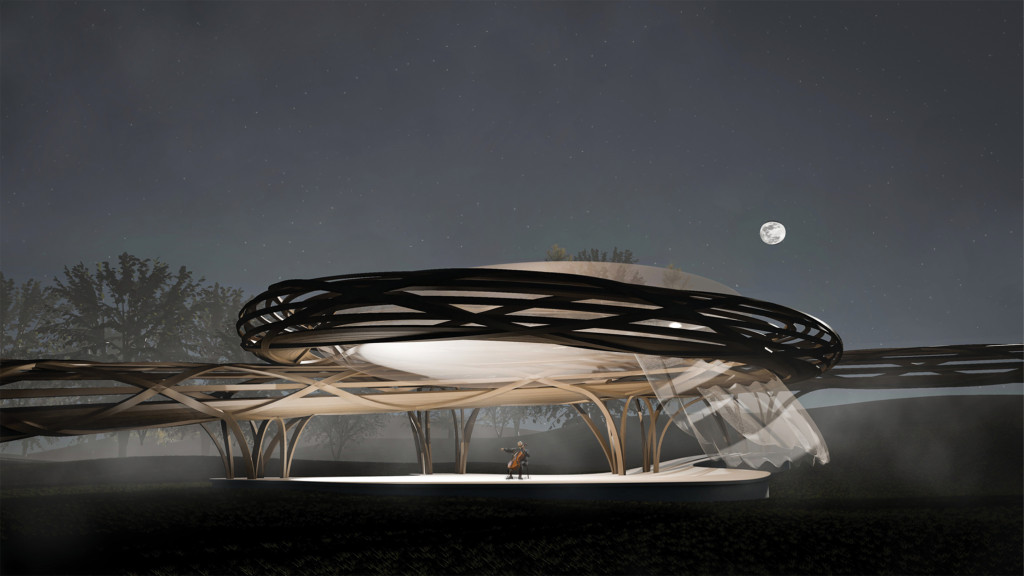
Final Project Images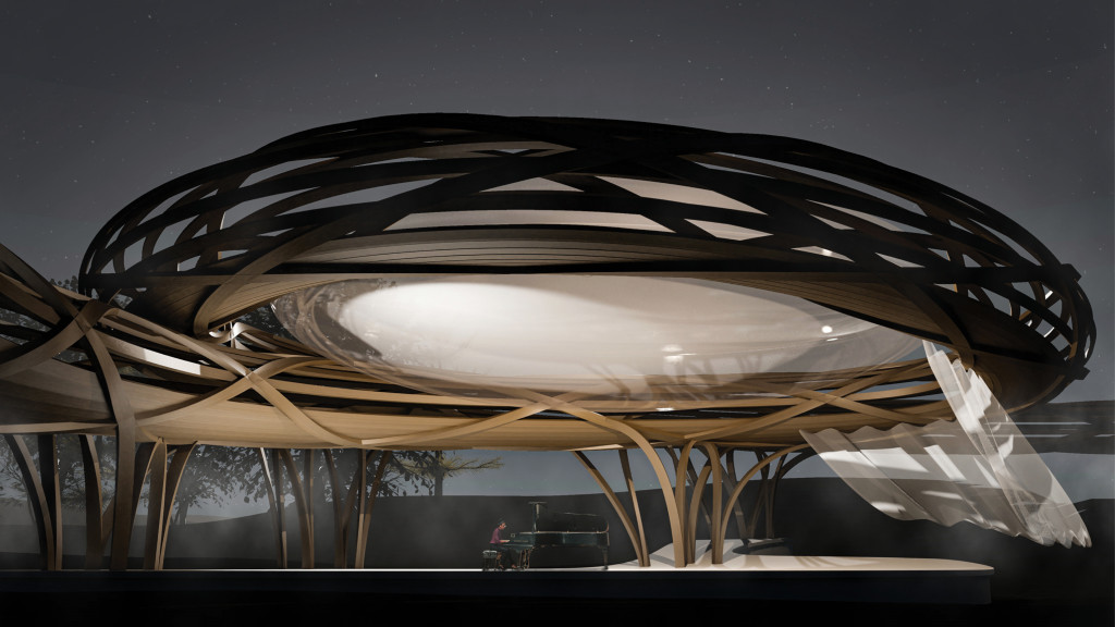
Ligamento is a project of IAAC, Institute for Advanced Architecture of Catalonia developed in the Master of Advanced Architecture 2019/20 by
Students: Zackary Bryson, Bruno Ganem Coutinho, Tomas Garcia de la Huerta Eluchans
Faculty: Tom Svilans