DATA INFORMED STRUCTURES// BYO+BYO // STRUCTURAL DESIGN AND GEOMETRY
The aim of this project was to design a pavilion on the rooftop of the IAAC Main Building. The pavilion would provide a space for social interaction, keeping in mind the climatic conditions of Barcelona. The structure of the pavilion had to be lightweight so as to benefit from the existing structure while providing shading.
REFERENCE// SAWMILL SHELTER
Our group drew inspiration from the Sawmill Shelter designed by the students of Architecture Association in Hooke Park, UK.
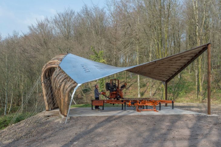
Sawmill Shelter
The Sawmill Shelter was analyzed on Karamba to understand its structural capabilities which helped us to design our own roof proposal. The conclusion was that with the cables, there was more tension inside the timber, which increased the stability of the structure.
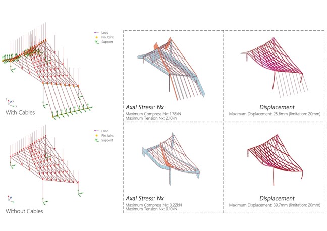
Sawmill Shelter_Karamba Analysis
ROOF DESIGN// OVERVIEW
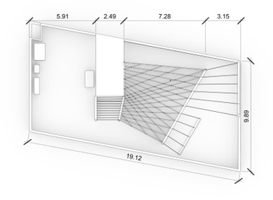
Roof Plan
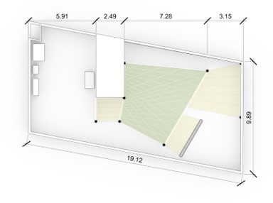
Floor Plan
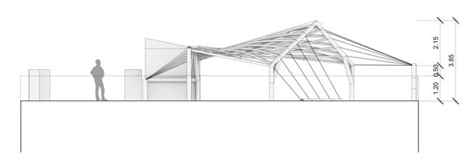
North Elevation
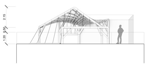
South Elevation
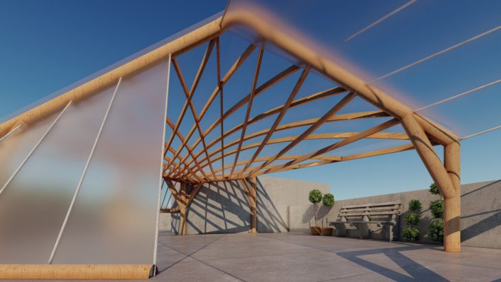
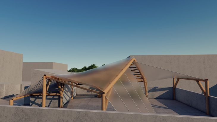
ROOF DESIGN// STRUCTURAL FORM
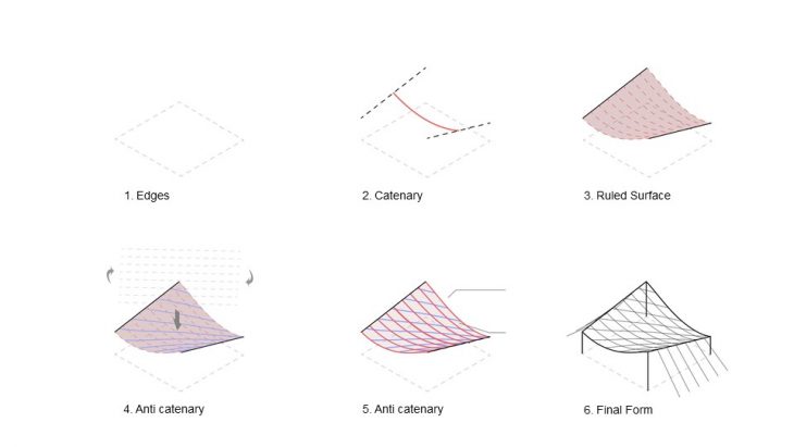
Form Development
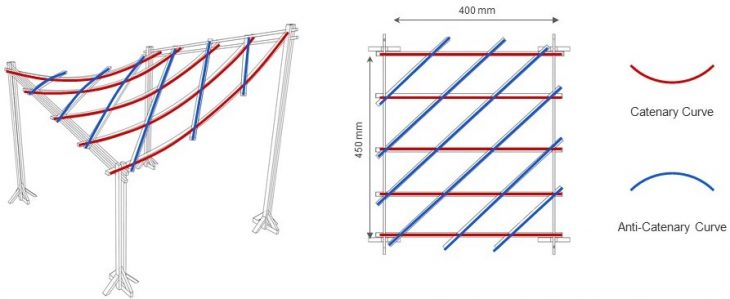
Curve Typology
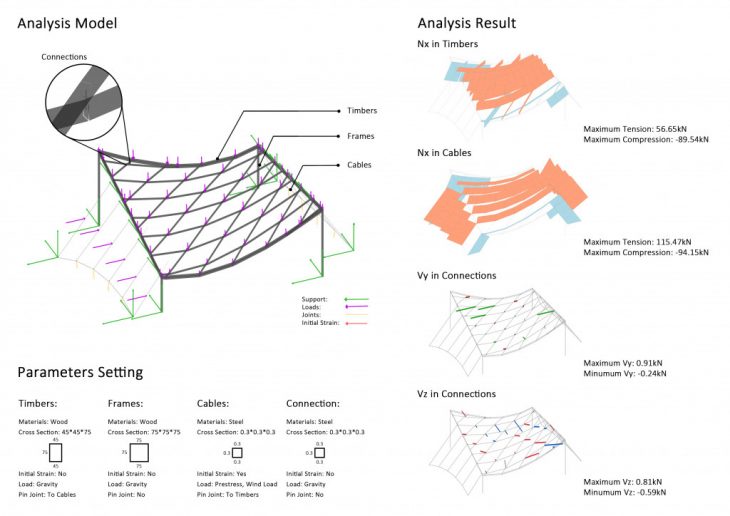
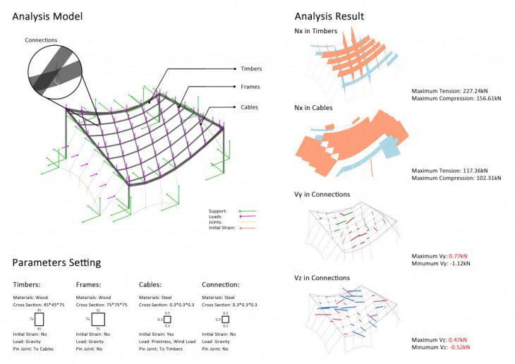
ROOF DESIGN//KARAMBA ANALYSIS
ROOF DESIGN// LATH JOINERIES// TYPE 1
Type 1 joinery between the timber laths was designed using timber blocks of cross section 45x45x90mm and ties going around the laths.
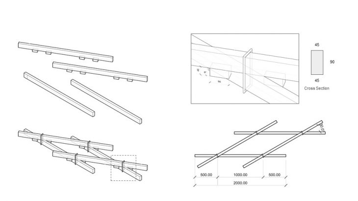
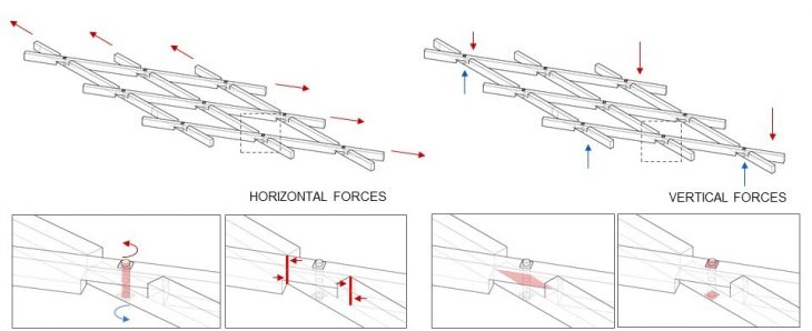
Diagrammatic explanation of Joinery Type 1
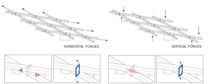
Horizontal and Vertical Forces on the Laths
The above diagram explains the behavior of joinery type 1. The blocks prevent rotation by compressing themselves (shown in red) whereas the ties prevent rotation and separation of the laths (shown in blue).
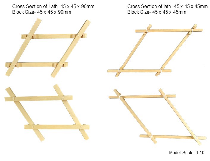
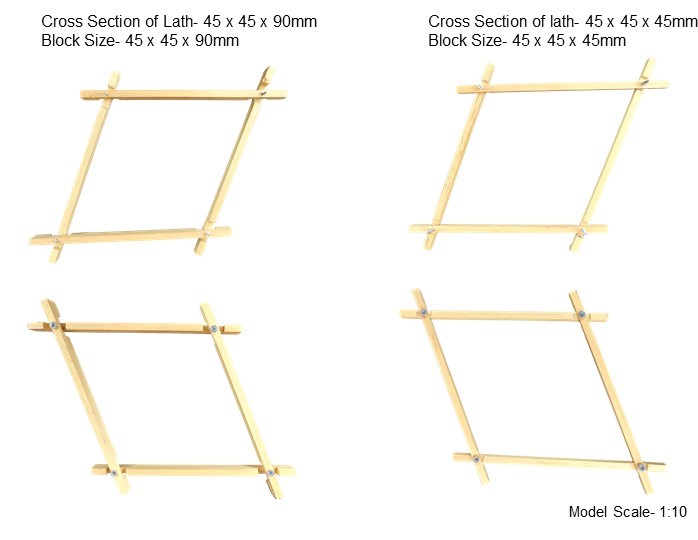
Physical Model made during Workshop
The joinery was constructed with two sizes of laths- 4.5 x 4.5 x 9mm and 4.5 x 4.5 x 4.5mm to understand how the cross section size affects structural stability and connection stability. The larger cross section proved to be more stable. The joint was tied with thread.
ROOF DESIGN// LATH JOINERIES// TYPE 2
Type 2 joinery between the timber laths was designed using notches in the laths and fastening it with bolts.
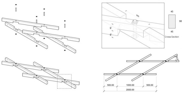
Horizontal and Vertical Forces on the Laths
The above diagram explains the behavior of joinery type 2. The notched part prevents rotation of the laths where as the nut and bolt holds the laths together and prevents shearing.
Physical Model made during Workshop
The joinery was constructed with two sizes of laths- 4.5 x 4.5 x 9mm and 4.5 x 4.5 x 4.5mm to understand how the cross section size affects structural stability and connection stability. The larger cross section proved to be more stable. The joint was held together with screws.
ROOF DESIGN// GLOBAL MODEL
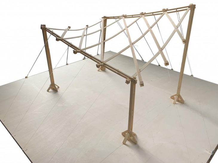
Global model at 1:10 scale
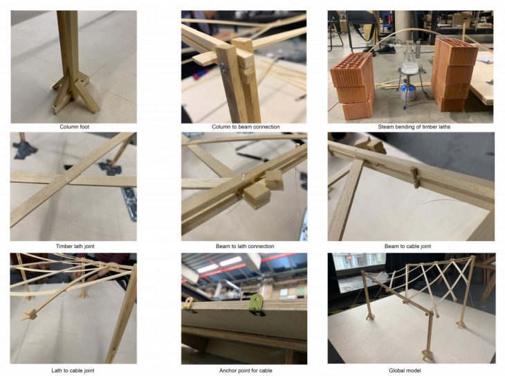
Joinery details for Global Model
This model was constructed by taking the joinery details of all connections from other teams and incorporating them into the global model. In spite of the global model not being the exact design of the proposal, the intent was to test the overall performance of the joineries in relation to each other. The scale of this model was 1:10.
ROOF DESIGN// CONCLUSION
The cables on both the directions make the structure more stable. In the catenary direction, the cable is attached to the beam and is pulling on the beam. In the Anti-Catenary direction, the cable is pulling on the laths directly. For the final construction, the number of anchor points of cables need to be reduced. To accommodate the timber laths on the edge beams connection, the beams have to be angled as per the angle of the laths. In the 1:10 scale model, the lath joints do not deform as much as expected, they are stable. In the Karamba test, the cables added on the four edges are helping the structure to be more stable.
This is a project of IAAC, Institute for Advanced Architecture of Catalonia developed in the Master of Advanced Architecture 2020/21 by: Students: Hairati Tupe, Liang Mayuqi, Nan Yin and Prarthana Sudhindra and Faculty: Manja Van de Worp, Raimund Krenmueller
