Body & Ornament: Robotic Processing of Timber as an Architectural Material
Workshop Overview
Historically, timber has been a versatile architectural material. Strong enough to carry forces through its body and soft enough to be moulded and carved with exuberant articulation in its appearance. Its use in building scale application however, fell out of favour due its reliance on skilled and manual labour. In particular the ornamental aspects of wood bore the brunt of the march of the mass production. Recent adaptation of industrial robots to architectural production offers the chance to have our cake and eat it too – advantages of mechanised production couple with the full-bodied and emotive qualities of architectural timber.
Workshop Goals
This workshop intended to explore such a design-space – a space of very many possible solutions, each transmitting forces to ground axially, whilst presenting itself eloquently in its external appearance.
Key Challenges
Form-finding of compressive spatial networks, particularly the underlying logic of form-finding of compressive skeletal structures.
Robotic path-planning for the fabrication and assembly process.
Although, the intended outcome of the workshop wasn’t fully reached. Due to time restrictions and technical limitations. However, through out the process a lot of obstacles faced resulted in a critical way of trying to overcome them. Extending our expertise and body of knowledge on how to overcome multiple problems that should arise in the future.
Such thing that is illustrated and explained in the following sections.
Design Process
First Approach
By: Sujay Kumarji
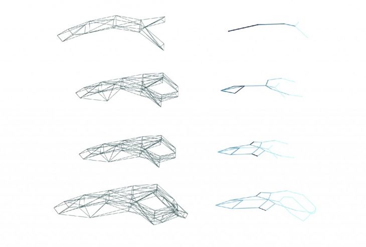
In this approach design iterations of the truss was developed using PolyFrames.
“ PolyFrame is a computational framework that allows the construction and manipulation of reciprocal polyhedrons for structural form finding. “
Polyframe helped simplify the geometry by identifying the structural skeleton and the forces acting on it.
While it seemed easy, initially, to be able to resolve the geometry, it did pose some problem of predicting the final geometry of the proposed truss. For that reason this iteration was discarded.
Second Approach
By: Omar Geneidy
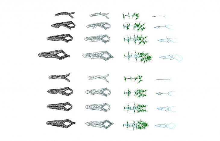
In continuation to the first approach, another line of development we were working on in parallel was to generate a grasshopper script that generates automatically the clustered prims used as an input for polyframe given a set of curves as input.
The idea was to speed up the iteration generation process using polyframe as it was very time consuming.
 The problem faced later on was that the shapes generated by polyframe were very unpredictable and very far from the intended shape of the structure.
A problem that could have been solved by a thorough research to understand the underlining mathematical and the geometrical principles behind the software, so that the inputs are fed into the software with an idea of how the output will become more or less.
Something that we couldn’t achieved given the limited time of the workshop
Accordingly, using the same concept, we developed another sc
ript that generates a truss structures given a set of curve as inputs. These trusses could be symmetrical or asymmetrical depending on the design. The script also generated them with respect to the available constrains: like robot reachability & maximum number of elements that can be used.

These structures were later fed into a custom-app developed by ZHcode that finds the compressive spatial networks of a given set of curves
Third Approach
By: Luis Arturo Pacheco
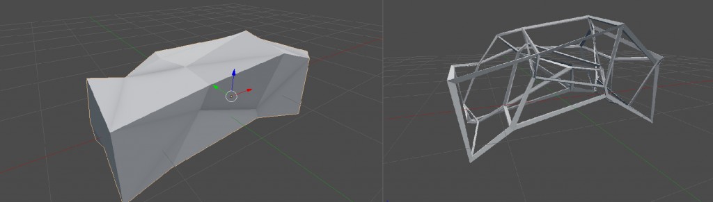
In parallel we were following another approach of generating the design for the structure using a completely open source software “Blender”.
Geometrical process description:
- Creating a box
- Populating it with random points
- Creating an armature from this points
- Deforming the armature to follow gravitational weight transfer (catenary similar to Gaudi’s approach to design Sagrada Familia)
- Creating parametric connectors for the each of the armature elements (edges)
The following geometry was achieved using Blender’s Cell fracture tool, particle system and soft body simulator:
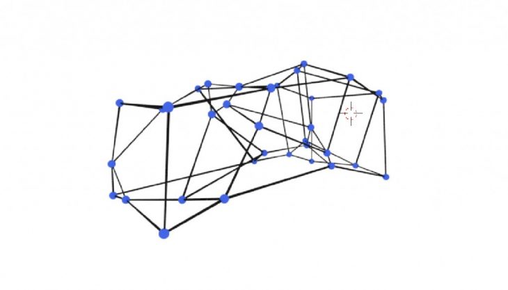
The generated geometry was later used to generate joints at the nodes using Syverchok (Grasshopper-like tool in Blender). The generated nodes could have been 3D printed to be later used as joints using the dimensions that was generated using a Python script.
Also, using Blender Animation nodes (another Grasshopper Like tool in Blender specific for animation ) a particle system was created (more efficient) inside animation nodes . This method allows for flexibility in simulating different attractors , obstacles, etc.
Fourth Approach
By: Hazal Y?lmaz | Ardeshir Talaei | Jean Nicolas Alois Dackiw
The fourth approach was the one that had the final output used in the later steps. It mainly involved using Kangroo with Grasshopper.
The challenges faced during the design process involved
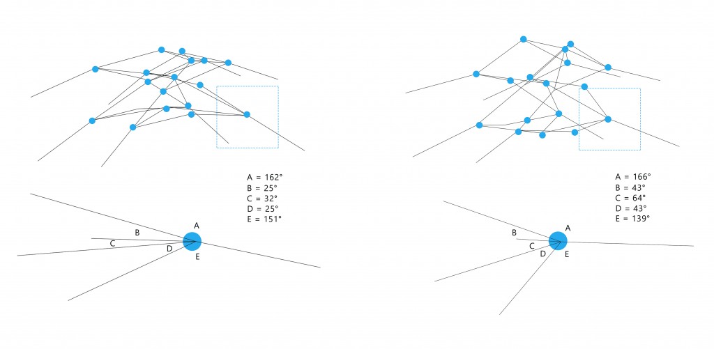
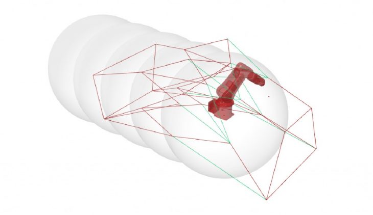
Problem 1: Reachability of the robots
This was solved by placing the structure’s anchor point within a bounding box which was designed according to the robots reachability limits.
Problem 2: Angles Constrains
Depending on our constrains, the maximum and minimum angles between 2 members were defined on Kangroo. (min:30 – Max:160)
Problem 3: Collision
To avoid collision of the tool head (gripper) with the saw blade, a different gripper of a smaller dimensions was used to hold the pieces.
Problem 4: Twisted Member
Changes in plane at the end of the wooden elements sections resulted in twists which had to be palanarized so as to be manufacturable.
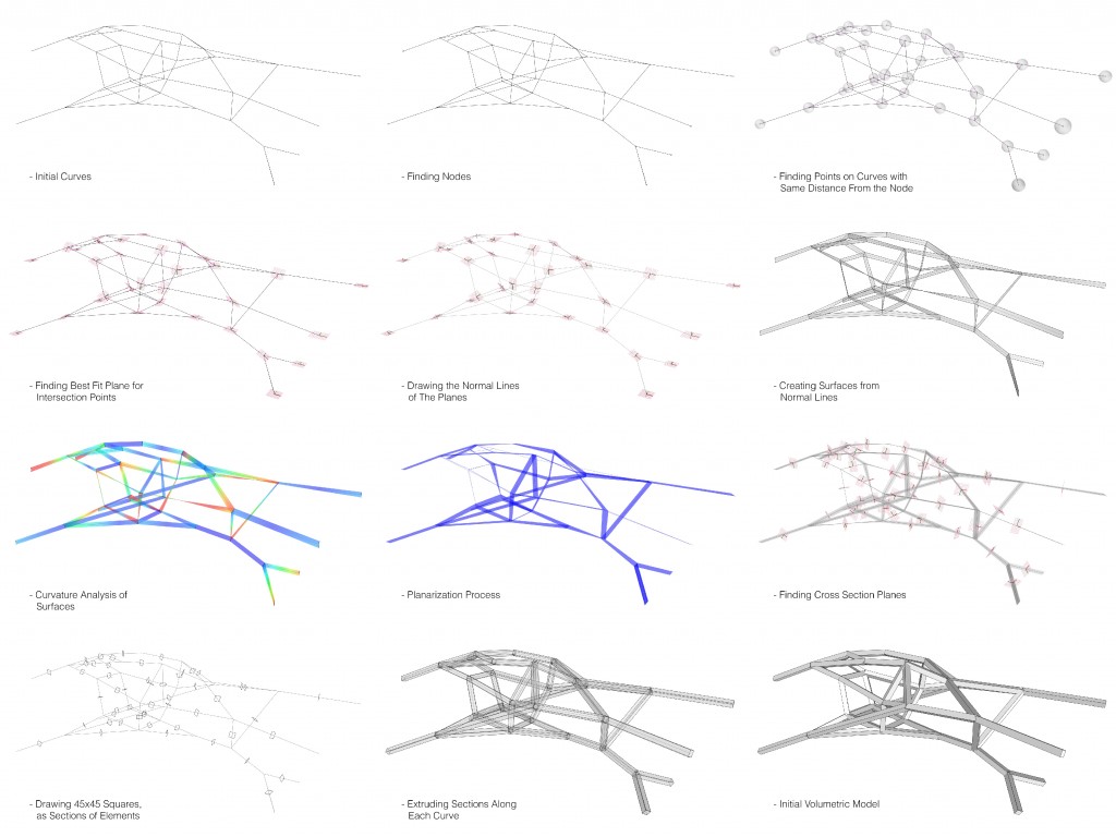
Volumetric Process
By: Soroush Garivani
Joints Details
Mitered Joints
By: Mohamed Owaze Ansari
Mitered joints that were 17.2°, 22°, 14.6° and 167.3° (from a previous design iteration) were explored. In order to miter these joints, the cutting planes defined were at the intersection of the 4 joints; But the angles between the planes could not be made perpendicular to each other, due to one member losing more material than the other, therefore reducing the strength of the joint. The planes defined were at the midpoint of the joining members, ensuring the loss of material on each member to be 50% or less. The methodology can be applied to other joint members as well based on this principle and can be later screwed in place.

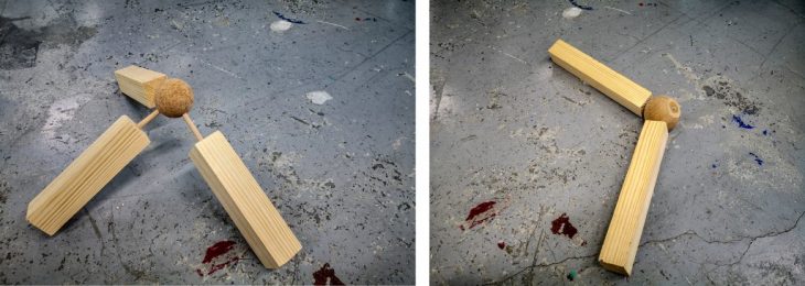
Spherical Node Joints
By: Filip Bielicki
Spherical node that was plausible with the existing robotic working range and also narrow angles, very difficult to saw were also explored. From a geometrical point of view, the source of the problem was placed in construction design, where members didn’t have rigid limits for angles. Because we knew about kind of the robot, we should prepare file this way, the even small robot can operate easily around saw. Also changing saw for a milling tool could result in a smaller area needed to make cuts, extending an operating area.

Flexi Wood Joints
By: Subhash Prajapat
Using elastic material rubber and Zip ties. Use of flexi joint in fancy furniture inspired us to do experiment with these joint manually for our design. we have developed a series of rubber joints from hard rubber and screw to the wood member and in the same way we made hole in the wood member and then use Zip ties for another iteration. These Flexi wood joint increase possibilities in developing fancy structure also its offer new flexibilities and aesthetic qualities unprecedented in the use of wooden joints or metal joint. It can be done manually only. The Problem with flexi joint is lack of structural strength and accurate angles. Using the other flexi materials like silicone, Gum, Hard Compound etc. could have increase the structural strength and aesthetic quality of the joint.

Comparison Between The Different Systems
By: Apoorv Vaish
Comparison between two of the joints that were explored by the joinery group with the help of the digital files created by Owaze and Filip. The joints are compared on the basis of their geometric flexibility of accommodating wide range of angles in the design, structural strength, ease of fabrication, aesthetics and robotic assembly.
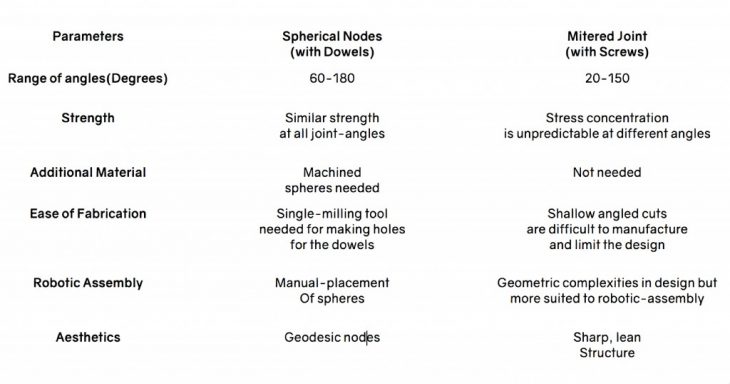
Finally, the mitered joint was used for the final design because of its aesthetics and since it is more suited for robotic-assembly.
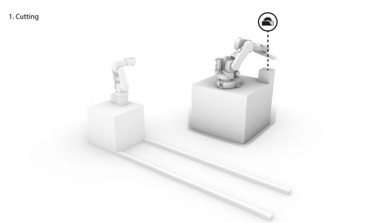
Fabrication Process
By: Andrzej Foltman | Riccardo Mura | Sebastian Voigt
Being part of the team that took in charge the robots set up was more than a challenge, as soon as the workshop started we figured out that to build such a big structure the robots ranges were not enough and we needed something that were at least could be easily moved.
First Step:
The first task was to build a rail on which the small ABB IRB 120 could move to reach all the points of the structure and place the pieces.
Once the rail was built we suddenly realized that the to robots needed some “fixed points” in space where the handover was safe so we had to set 5 “stations” on the rail where to calibrate the robot.
Second Step:
When we finished the two robots set up, the problems became bigger, at this point we had a design for the structure and we needed to fit that design inside the set up.
At this point the biggest issue was the fact that the whole structure had very complex angles in the joints and to cut all of them we were forced to move the circular saw very far out from the zero of the first robot, this helped us to reach a bigger number of cuts but still not all of the.
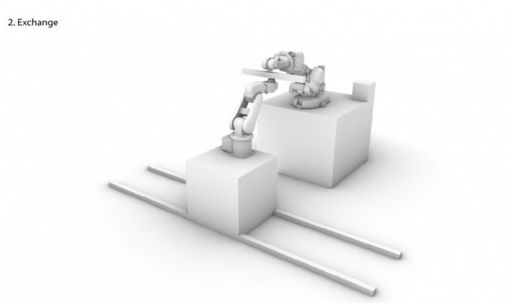
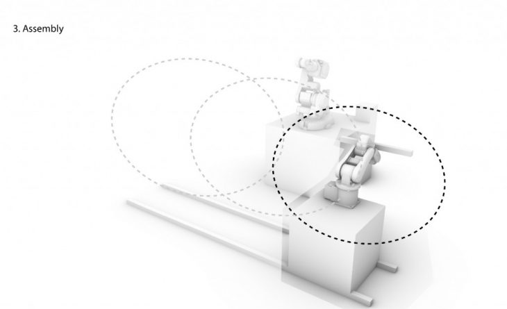
Third Step:
After the member had been cut by ABB IRB 140, the piece was handed over to smaller robot to assemble the structure. During the process a few problems arose. Some of the members were out of robotic reach, others would be blocking the further movement of the robot. Some angles of pieces to be assembled were also problematic. During first simulations, 32 out of 52 pieces could be assembled by robot.
Problems:
- Robot working range was not enough to accomplish all the cuts we needed
- The stationary circular saw put a lot more limitations to the cuts we could achieve
- The space for the handover and the placing was tight and limited
- Some members were out of placing reach
- Some pieces blocked robots transition into another assembly position
Solutions:
A lot of problems could be avoided just by mounting the circular saw on a rotating table, which could have helped us to match in a better and faster way the cutting plans and the blade plan.
Another solution could have been to check that all the angles inside any joint should have stayed in a specific range. Few changes could be incorporated into design, eg. members not blocking robots movement.
Logistics & Documentation
By: Stefano Meloni | Omar Geneidy
Logistics & material gathering were mainly Stefano’s task along with helping out in setting up the space for the fabrication process.
Documentation was another key aspect, required to gather all of the info in one place that can be used later as a reference for future projects. For that a project video was done jointly by Omar & Stefano, a presentation for the workshop was prepared by Stefano and finally a unified blog post for the workshop was put together by Omar.
Credits
Senior Faculty
Shajay Bhooshan | Alicia Nahmad
Assistant
Kunaljit Chadha
Lab Support
Armin Akbari
Participants
Andrzej Foltman | Apoorv Vaish | Ardeshir Talaei
Filip Bielicki | Hazal Y?lmaz | Jean Nicolas Alois Dackiw
Luis Arturo Pacheco | Mohamed Owaze Ansari
Omar Geneidy | Riccardo Mura | Sebastian Voigt | Soroush Garivani
Stefano Meloni | Subhash Prajapat | Sujay Kumarji