MANIFESTO
Dunes aims at developing a Desert Pavilion designed to serve as an oasis of rest and communal gathering.
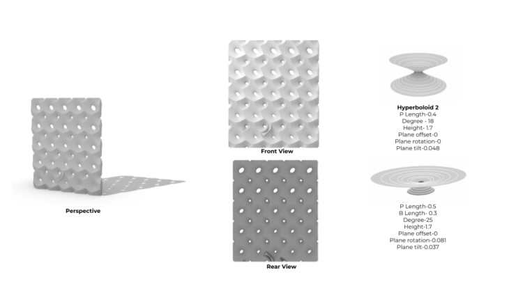
The project, located in the hot and dry desert region of Dubai, intends to activate the user’s senses, namely visual and thermal. This is done by crafting aesthetic openings by employing hyperboloids as the defining geometry. The perforations on the façade of the structure aim to channel Dubai’s hot sun and negate high wind speeds into the space in accordance with seasonal variations.
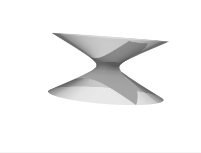
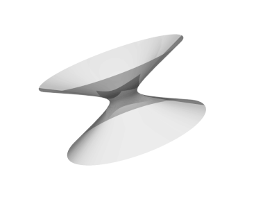
Investigations to develop the project include experimenting with combinations of hyperboloid geometries through a physical plaster model and further optimizing them through a series of iterative enclosures by use of parametric design.
SITE LOCATION & ENVIRONMENTAL ANALYSIS
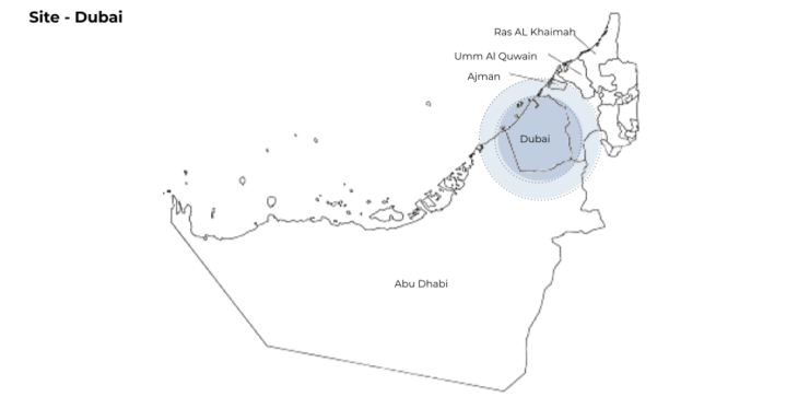
The site is located in Dubai, the eastern part of the Arabian Peninsula on the coast of the Persian Gulf, It is part of Asia and the northern hemisphere. Dubai has Hot & dry climate with prolonged, windy and humid Summers, with an Average High of 40 °C degrees celcius (104 °F) and an Average Low – 30 °C (86 °F). The Hottest months are July & August. It has Cool and mild in Winters with an Average High – 24 °C degrees celcius(75 °F) and an Average Low – 14 °C (57 °F).
Environmental Analysis
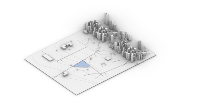
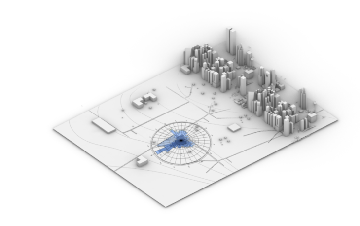
SITE
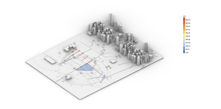
SUN PATH DURING SUMMER
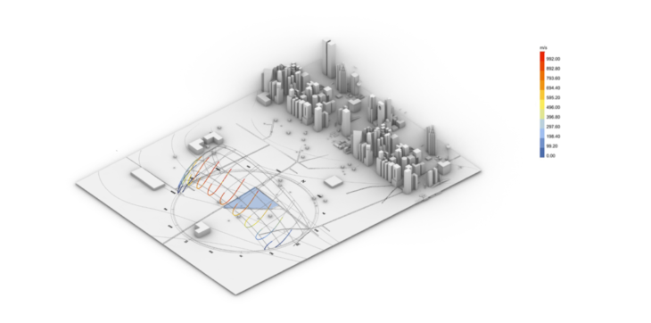
SUN PATH DURING WINTER
The site is exposed to maximum solar radiation towards the southeastern-western cardinal points during the month of January and the northeastern-western coordinates during the month of July. This would mean that these areas are to be designed with perforations with minimal surface area to help diffuse the sunlight and possible heat gain.
WIND SPEED ANALYSIS
Wind speeds are strongest towards the northwest, mild at the southwestern/eastern side and least at the eastern coordinate. This would mean the design should have maximum enclosures at these points according to the strength of the wind speeds.
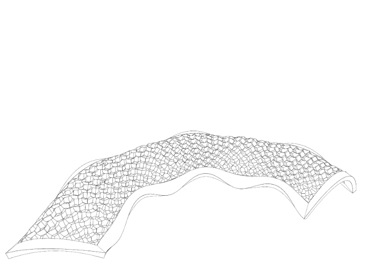
DESIGN DEVELOPMENT
FORM GENERATION
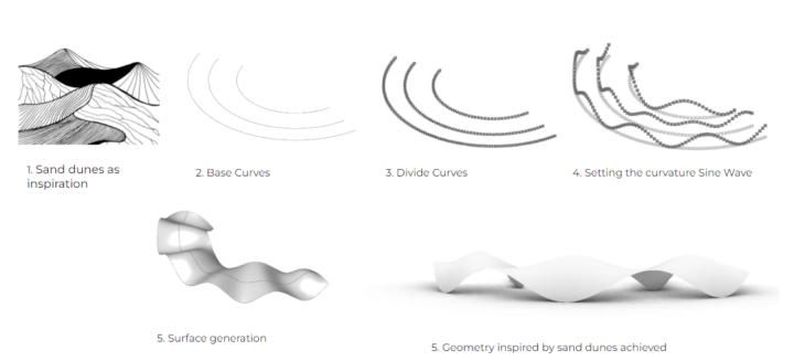
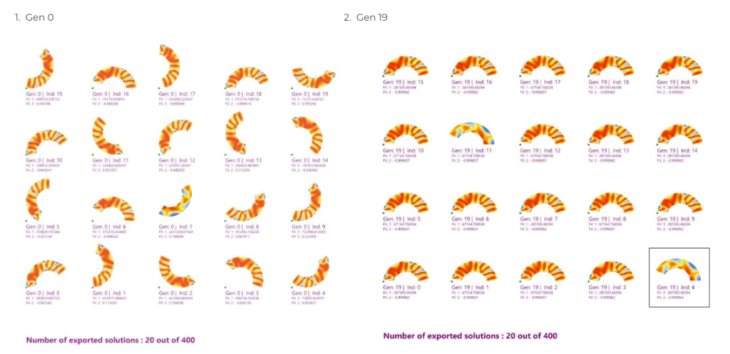
EVOLUTIONARY OPTIMIZATION
Multi objective optimization was done using WallaceiX with the following parameters:
Parameter 01-Minimise Radiation (0.5 -0.8 values) to change the sine wave curvature related to the sun radiation.
CURVATURE
Parameter 02-Maximise ventilation to change the rotation of the form on the site related to the main wind direction.
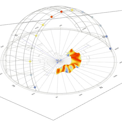
ROTATION
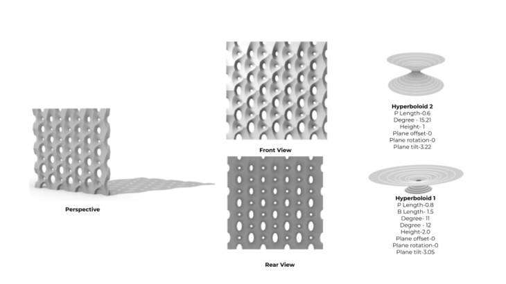
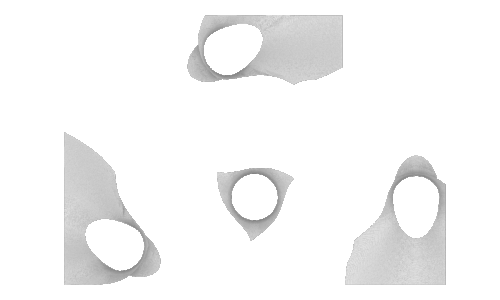
PERFORATION LOGIC
After achieving the optimised geometry. A perforation logic was applied to make it a data informed design.
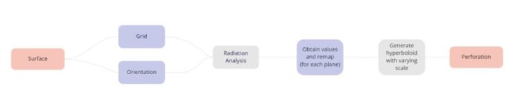
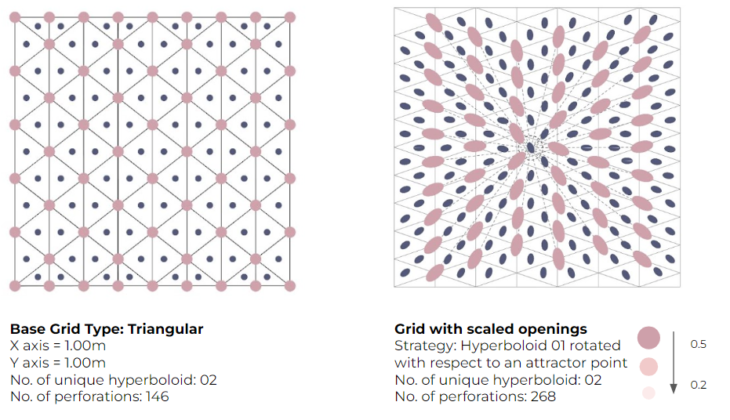
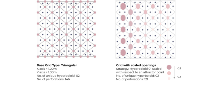
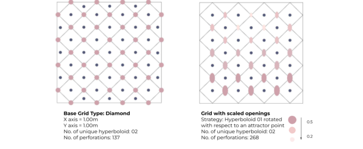
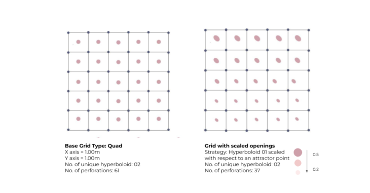
GRID EXPLORATION- GLOBAL VARIATIONS
ITERATION 01
Top view-Shadow Movement
ITERATION 02
Top view-Shadow Movement
ITERATION 03
Top view-Shadow Movement
FINAL ITERATION
Top view-Shadow Movement
LOCAL VARIATION
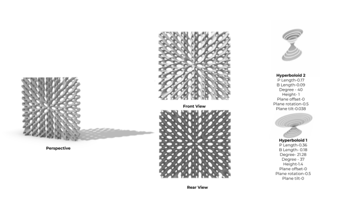
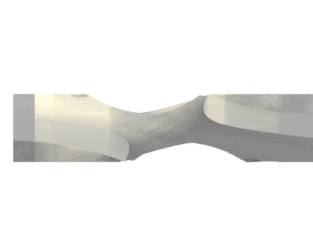
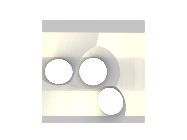
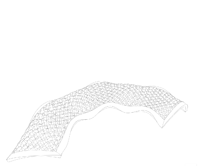
The final grid and the hyperboloid parameters was then applied onto the form.
The perforation size was scaled according to the radiation on the surface, to achieve a data informed design.

COMPARITIVE STUDY-INTERIOR DAYLIGHT ANALYSIS
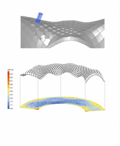
Analysis with Cylindrical punctures
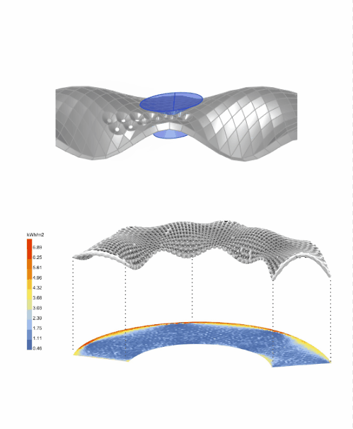
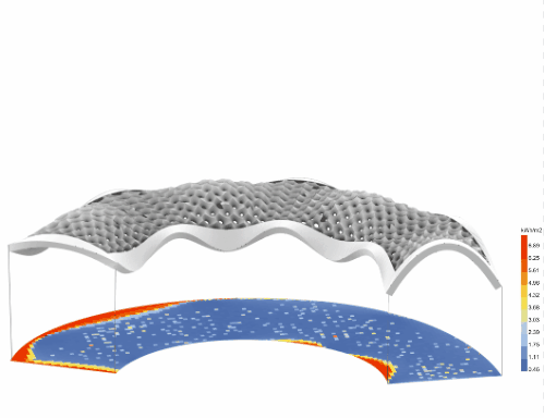
Analysis with scaled hyperboloids Analysis period: Hottest month Date: July 21st Duration: 7:00 – 21:00
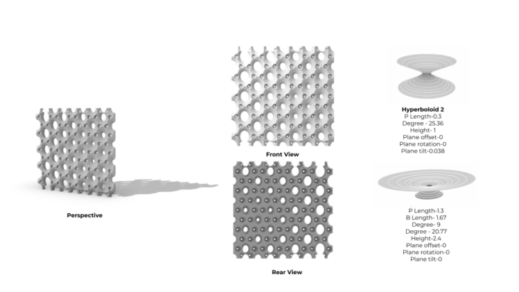
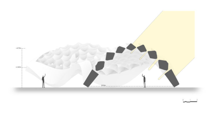
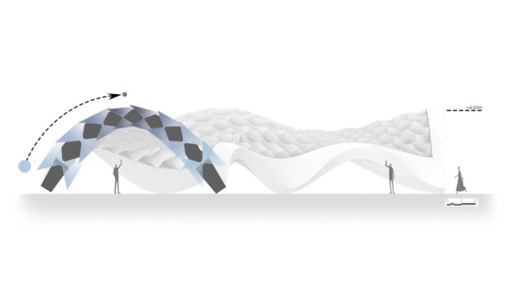
DESIGN DETAILS
Plan
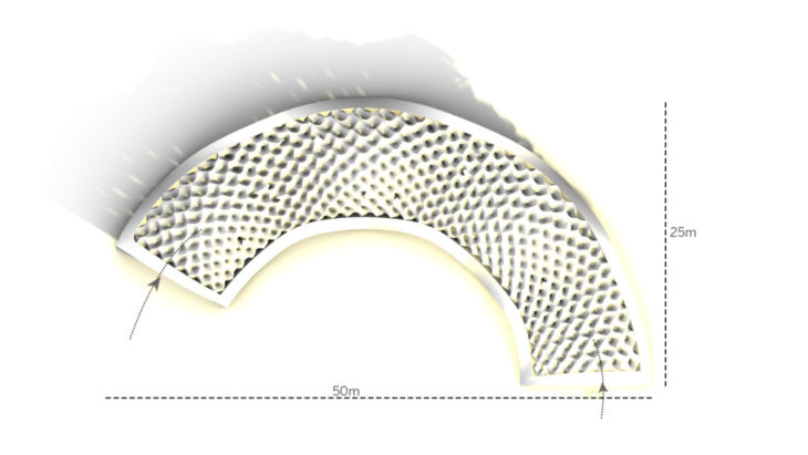
Section
FABRICATION
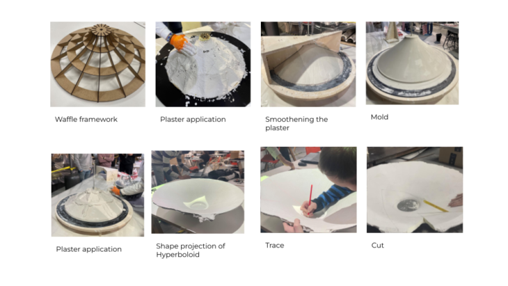
PLASTER WORKSHOP
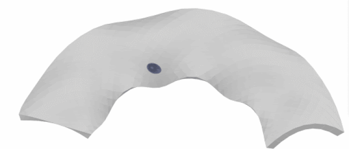
The workshop led by Albert Protoles (head of the model department in Sagrada Familia, Barcelona) consisted of learning and creating a piece of plaster intersecting hyperboloids, which is the same technique that was used in the construction of the Sagrada Familia by Antoni Gaudi.
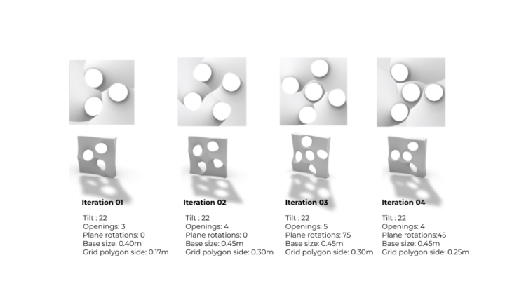
For the prototype we had to make we considered Tilt and rotation as parameters as Dubai has harsh sunlight and high radiation levels.
TILT
ROTATION
With these 2 factors in mind we made the iterations keeping the tilt constant and varying the number of openings.
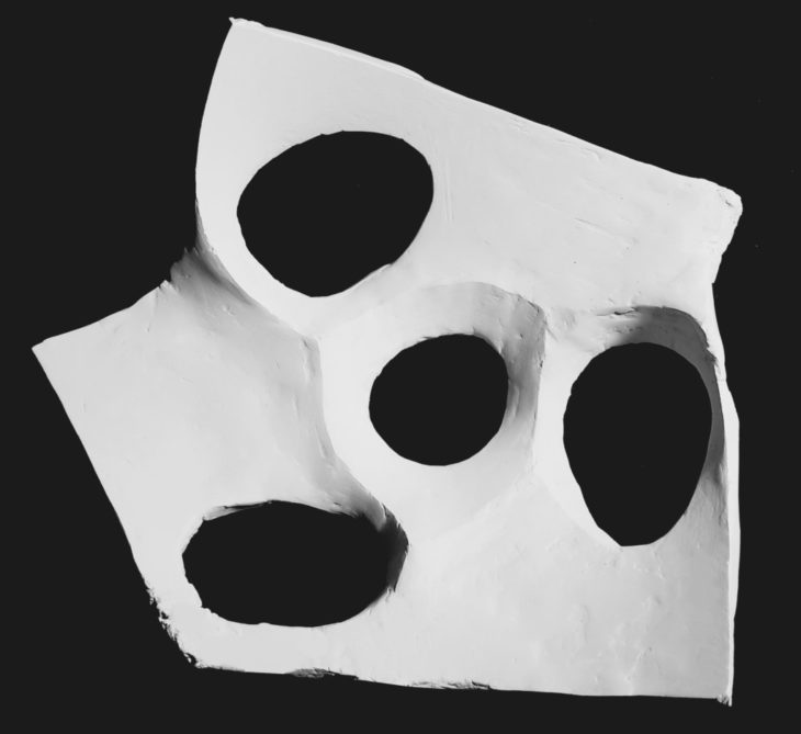
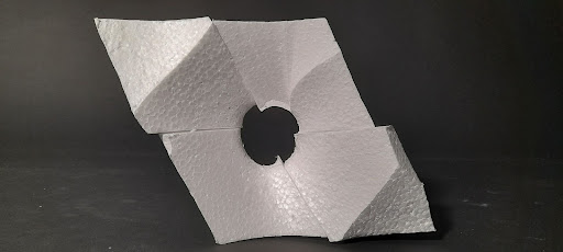
PROTOTYPE
Iteration 04 was selected to make the prototype because of its interesting triple points.
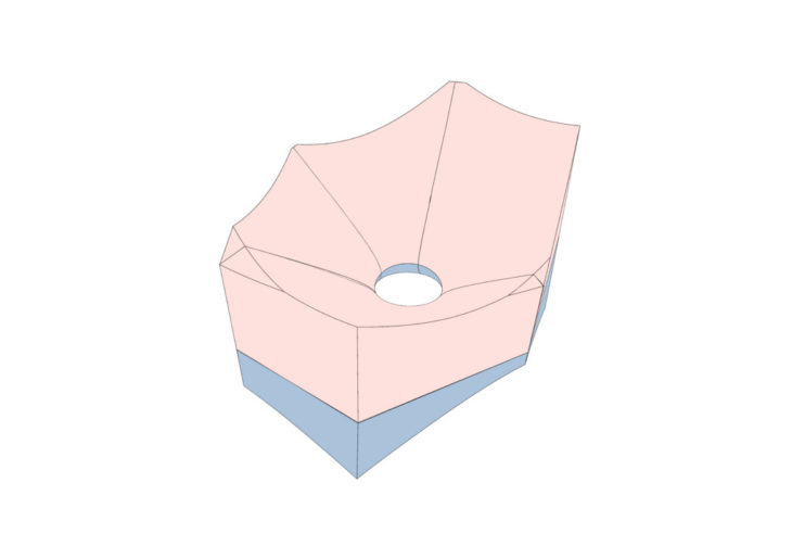
Ancillary pieces | No. of pieces: 03
Central Piece | No. of pieces: 01
Exploded view
PROCESS
Composition
ROBOTIC FABRICATION
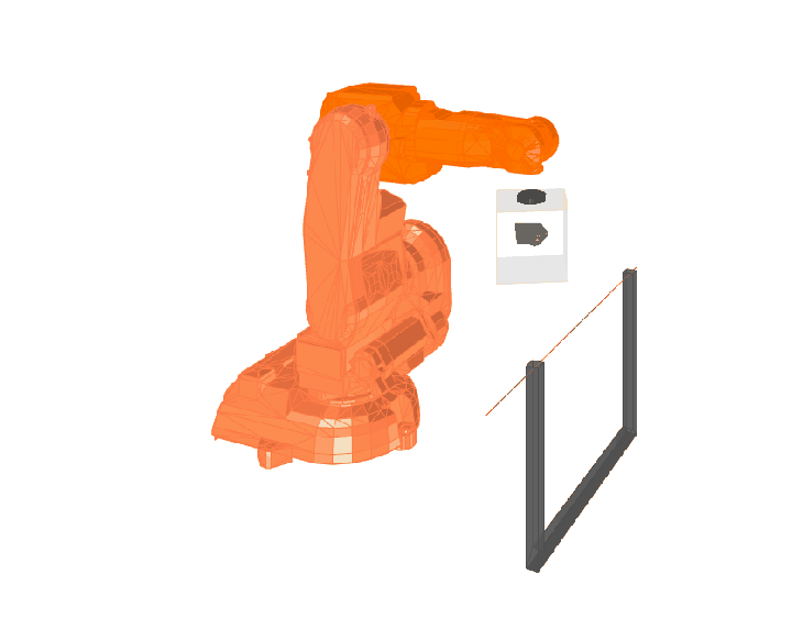
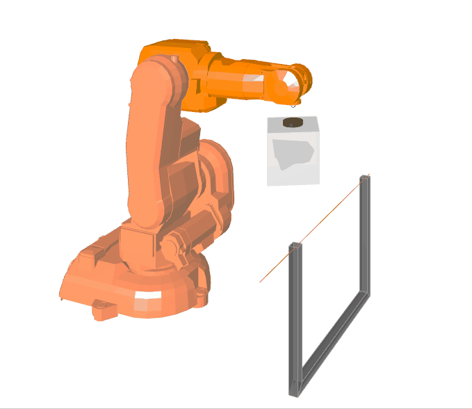
Prototype Test Piece – ABB Robot
The following series of images showcase the piece that was used for the first test piece for the robotic fabrication process.
The piece from the structure chosen for robotic fabrication
View of the piece
The top half of the piece
The bottom half of the piece
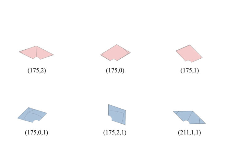
Catalogue of all the modules for robotic fabrication
Example of the robotic simulation – Piece (175,2,1)
Average duration for robotic fabrication of each piece was 6 minutes
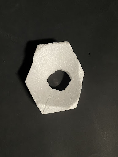
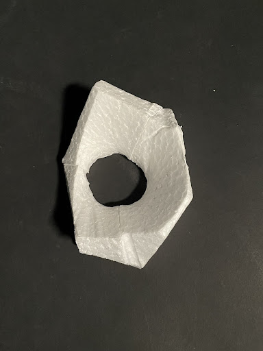
Fabricated pieces (Top image: Top Piece & Bottom image: Bottom Piece)
</p>
Prototype Sectioned Wall – ABB Robot
The following series of images showcase the section of the wall that was used for the robotic fabrication process.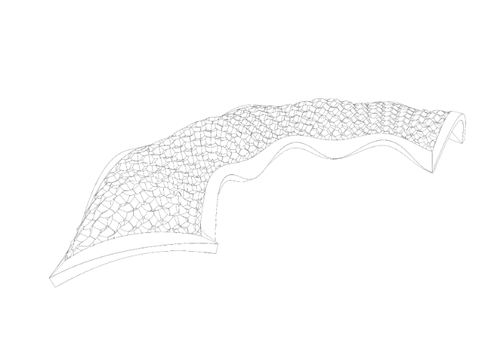
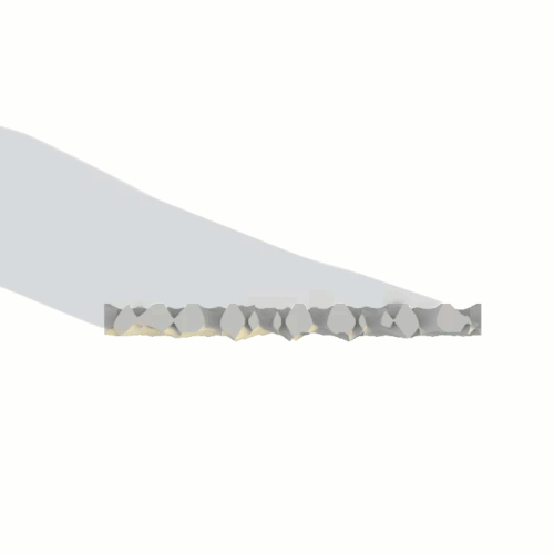
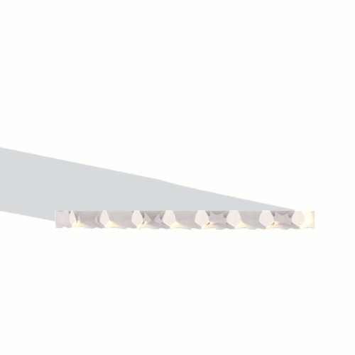
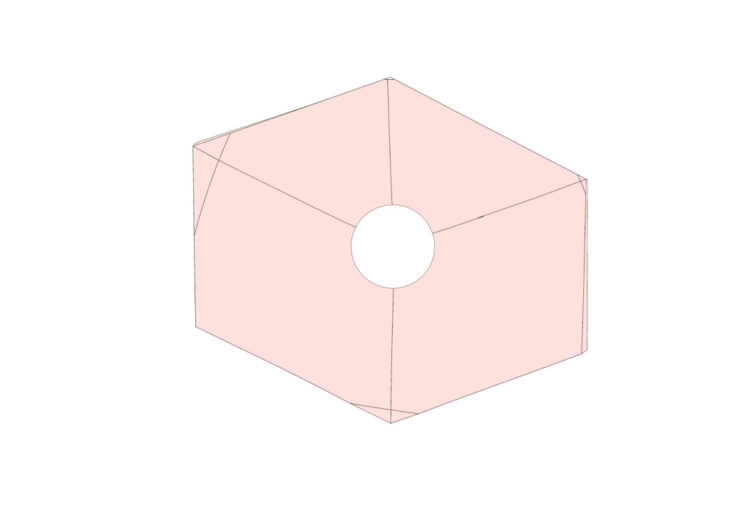
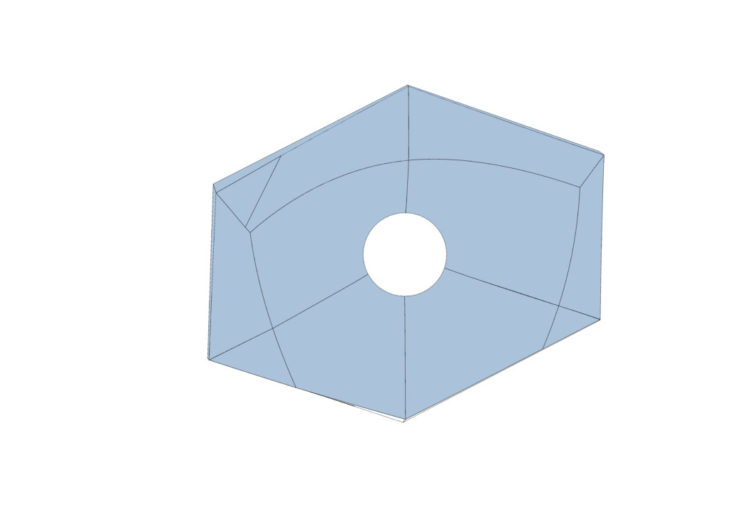
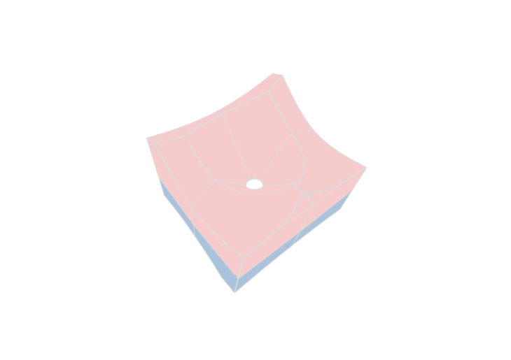
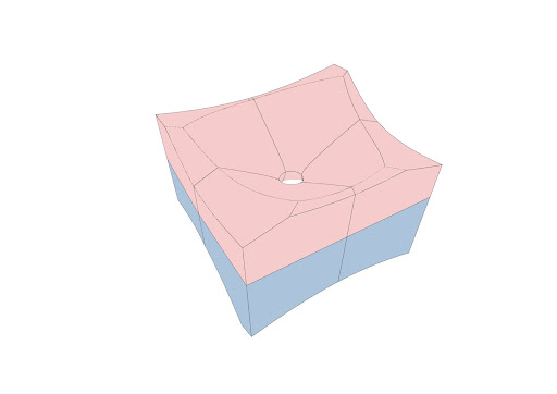
The section of the wall chosen for robotic fabrication

The sectioned wall
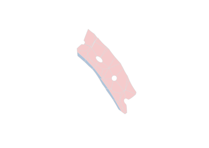
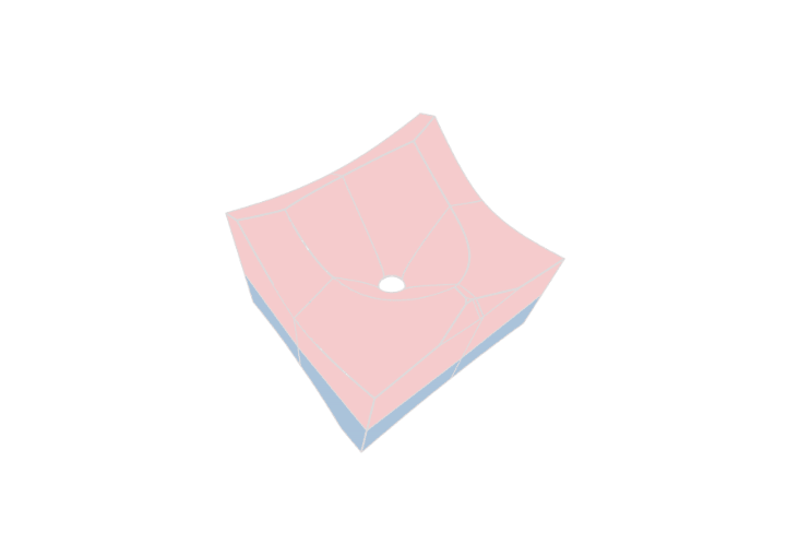
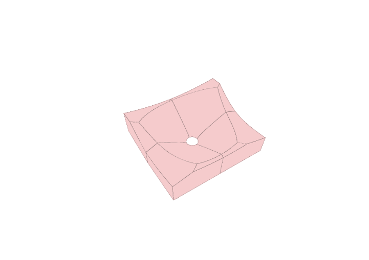
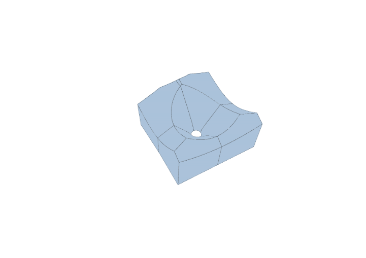
Exploded view of the sectioned wall (Pink represents the exterior part of the sectioned wall and blue represents the interior part)
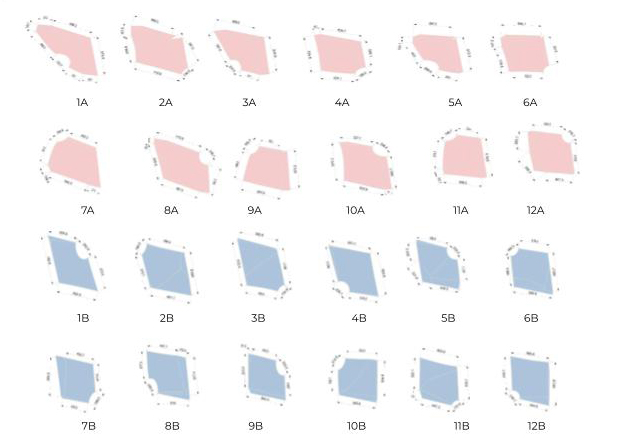
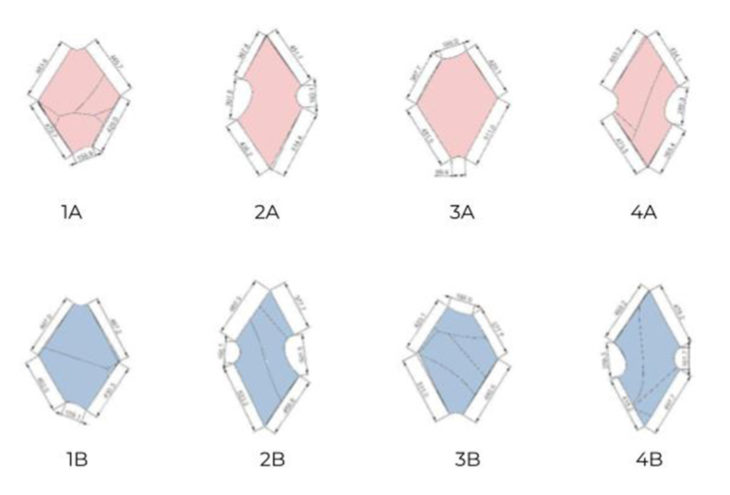
Catalogue of the 16 modules for robotic fabrication of the sectioned wall
Example of the robotic simulation – Module 1A
The final fabricated section of the wall
</p>
Robotic Fabrication Workshop – KUKA Robot
The following series of images showcase the fabrication of the during the Robotic Fabrication Workshop conducted using the KUKA robot.
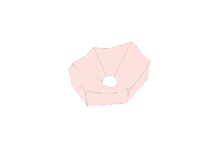
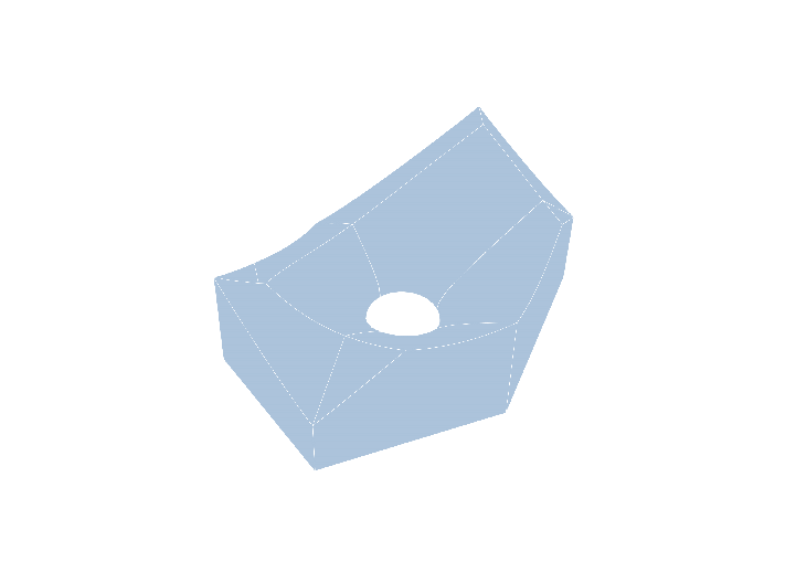
The part of the structure that was used for robotic fabrication for the KUKA robot
Stereotomy of the piece
Stereotomy of the exterior face of the piece

Stereotomy of the interior face of the piece
Catalogue of the modules for robotic fabrication
</p>
WALKTHROUGH