A Holey Place
CHRISTOPHER BOOTH
?PEK ATTARO?LU
JORDI VILANOVA
The aim of this project was to design a small, temporary pavilion inspired by an exploration of mesh topologies. The pavilion was to have a maximum size of 6M x 6M x6M, and apart from the development of the form should also include considerations relating to it’s possible manufacture from sheet metal.
MESH DEVELOPMENT
Initial mesh exploration was varied. A number of quite distinct forms were considered, all having in common a relatively simple coarse mesh of quads and tris (triangular faces). A number of different ways of analysing the proposed forms was used – curvature analysis and striping being shown below. In grasshopper the direction of stripes on a mesh can be controlled to give a desired outcome, as long as the coarse mesh is constructed appropriately and correct procedures followed. In particular it is worth noting that quad faces give more and easier control than triangular faces, and that all internal vertices should have even valence. Triangular faces are not to be avoided however – they offer possibilities quads do not offer and can be useful if used correctly.
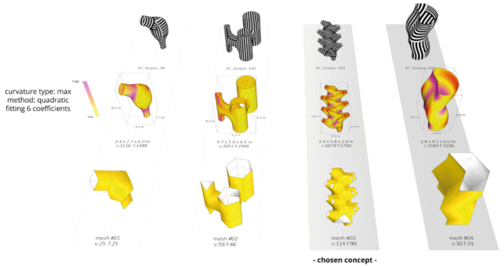
Initial mesh ideas
Of the 4 initial coarse meshes shown above, we chose the one with ‘holes’ for further topological exploration, in part for reasons of aesthetics and in part because we believe those ‘holes’ could be ideal forms for supporting the pavilion (feet) and structurally in general. The holes themselves are based on only quad topology, but the overall form has a small number of tris.
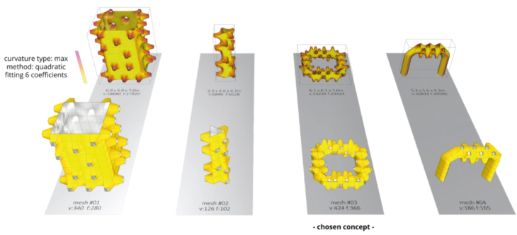
Mesh concept exploration
Concentrating on possible topologies incorporating this type of hole, we explored more shapes such as the columns, the ring and the arch shown above. Again mainly for aesthetic reasons and ideas of appropriateness of the shapes for a pavilion of the desired dimensions, we chose the ‘square’ format in the image above, but with concerns as to how to ‘shrink’ it.
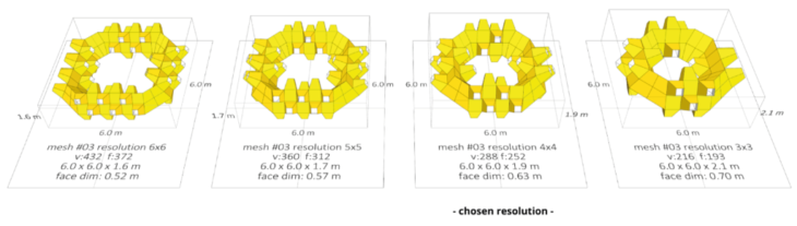
Concept resolution
This next stage of exploration is effectively a study of how to maintain the overall concept and make it smaller. We explore here the result of reducing the number of units along the straight edges of the square.
CONCEPT DEFINITION – WORKING WITH A SMALLER SCALE
We decided that the most appropriate solution for a pavilion of a maximum of 6M x 6M x 6M was to consider a single corner of the square to be close to that size, but nevertheless to propose that 4 corners could be used instead of one if possible.
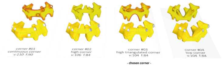
Working now with a single holey corner, we explored some final possibilites : could an area be made so low that people could look over and even climb over it? Could an area be made so high people could walk under an arch to pass through it?
Concept mesh development – Corner
The topology adjusted to include an arch of 2.2M height in the corner convinced us most.
Mesh face topologies
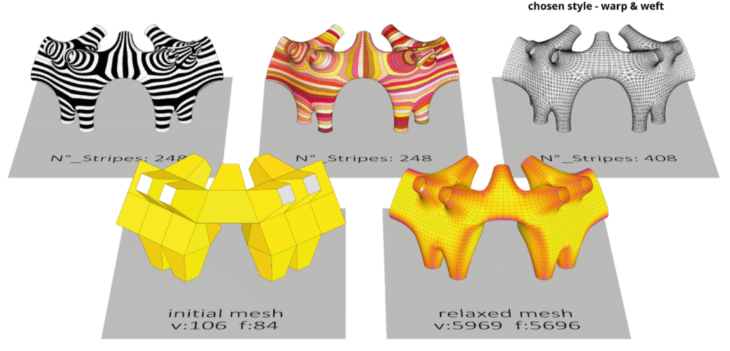
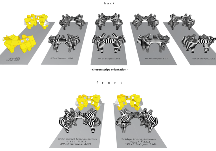
Chosen corner design – Stripper, and Warp & Weft versions
Our mesh topology exploration and relaxation had now passed through a number of stages and resulted in a form we were confident was visually interesting, and could be structurally sound if fabricated and assembled with appropriate materials and techniques. To proceed to possible fabrication strategies we developed a warp and weft model (above, back row, right).
FABRICATION CONSIDERATIONS
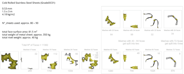
Our initial warp and weft model was analysed statistically in grasshopper to begin to understand the hurdles and complexity that construction could present. Grasshopper makes it fairly straightforward to analyse the number of strips, their lengths, curvature, etc. It was clear too from the overall symmetry that every strip had a symettrical partner, and that, for example, matching these partners could be a help for nesting: if parts can be cut from sheet material either face-up or face-down (which is the case normally using sheet metal) then parts with simpler curvature when flattened – they could be called ‘C’ -shaped parts – can normally be nested efficiently by placing one face up beside its symmetrical partner face down. An intriguing fact came to light too – there were ‘sets’ of strips falling naturally into groups of 8. This is a direct result of the level 3 Catmull-Clark subdivision applied to the coarse mesh topology.
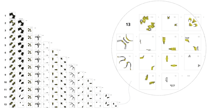
Disassembly study – Disassembly thinking of assembly strategy
But a global strategy for assembly was missing and we needed to analyse some possibilities. One study we made was to simulate taking the pavilion apart – a process that would also have to be done if it were to be built – but to do so thinking primarily of how it could be put together. This study helped understand the complexity of planning to assemble a warp and weft pavilion with a large mix of strip lengths. It also let us estimate the number of standard metal sheets might be required to produce the strips. Although not based on a full nesting, the percentage of strips we nested let us extrapolate to an estimated requirement of between 80 and 90 sheets measuring 1.5M x 3M.
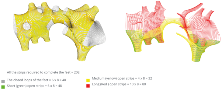
Another study gave us some insight to the potential complexity of assembly: we studied which strips would be required to be assembled to completely finish the assembly of the feet of the pavilion. It turns out that while the closed loops of the feet (placed horizontally) are relatively short and ‘manageable’, the open strips that cross them vertically were a mix of lengths including some that were amongst the longest of all.
Assembly
We decided to cut the longest strips in three and a large number of long strips into two to make assembly more manageable. This makes for a lot more individual strips to be made, tagged and tracked, but should bring assembly into the realms of being reasonably possible. We would entertain the possibility of shortening strip lentghs even more so that the assembly would take place in warp and weft sets of 8 strips horizontally and 8 vertically for each quad of the original coarse mesh – the number of meshes increases again but also confidence in being able to assemble the pavilion. Our proposed solution was an intermediate compromise, and although the world of rhino, grasshopper and several other plug-ins had let us get to this point, it is very clear that hands-on prototyping of scale models would be the most valuable next step to gain further understanding of how to tackle assembly of warp and weft structures.
Connections
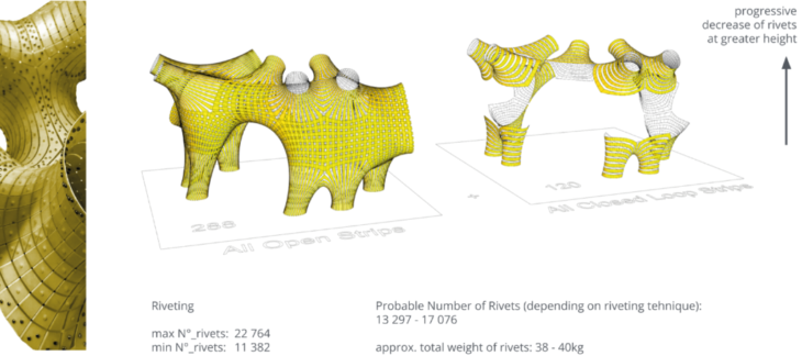
Our proposed connection technique is pop rivets. We proposed using a different number at different places on the structure – essentially more lower down and less higher up. The practicality of this proposition would need to be tested before committing to it – here a full scale model of e.g. a narrow strip of the pavilion might be more useful than a scale model of the whole pavilion.
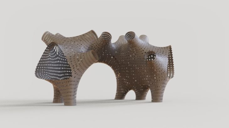
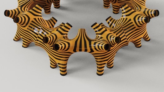
Above is an image of a monochromethe version of the warp and weft pavilion – the holey place. It is a holey place on different levels: there’s a hole big enough to walk through – the arch – and round holes big enough to look through. There are small square holes between the warp and weft strips, and there are two large triangular holes at the ends of the corner structure, which would be barely visible if 4 corners were placed together as we propose, but which would dominate from a visitor’s perspective because of their height (at eye-level for most people) and because one can be seen from most possible routes of approach.
And what if we were to build this holey place as proposed but still colour it as per our striping studies, and place four corners together again in a square? The final images below give an idea.

A Holey Place is a project of IaaC, Institute for Advanced Architecture of Catalonia developed at Master in Robotics and Advanced Construction (M.R.A.C.) in 2021 by,
Students: CHRISTOPHER BOOTH, ?PEK ATTARO?LU, JORDI VILANOVA
Faculty: Andrea Graziano, Eugenio Bettuchi