ABSTRACT
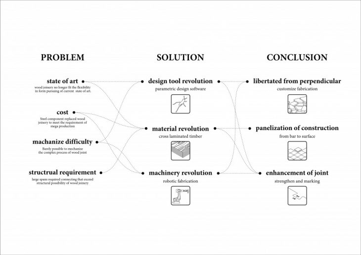
Joinery, the skills to join separate pieces to produce a more complex item of timber. It is now facing several obstacles since industrial revolution which has led to the decline of traditional joinery industry, such as cost, mechanize difficulties and structural aspect of problems, the traditional joinery is not able to satisfy the requirements of modern architecture. This research proposes a new design method to redefine traditional joinery from three perspectives, geometry, material and fabrication that lead to three main expected results, customization, penalization of the construction and enhancement of the joint by taking the advantage of revolution of 3d modeling software, material innovation and digital fabrication. This research tests the potential of joinery using parametric design software and fabricates it with 3d printing and robotic milling to process complex geometry and learn the advantage and disadvantage of digital fabrication by comparing with the traditional joinery fabrication process simultaneously. As a result, the joinery is able to be liberated from the traditional frame structure system to achieve more complex form and meet the modern architecture trend at the same time remains efficient and sustainable. The surface expended joinery in a multiple axis interlocking systems can assemble to a shell structure with controllable joint, optimized division following principal stress line to achieve better efficiency on material utilization and structural performance.
This research stands for the perspective that with the revolution in fabrication and material can solve the problem traditional joinery was facing since 18 century, and those solutions might lead to two simple expected results, which are liberated the construction from a perpendicular system, and penalization of construction and enhancement of joint. Liberated the construction from a perpendicular system: flexible production is not dependent on the modular grid of interchangeable parts. Consequently, it is becoming evident in wood frame panel construction that the grids introduced by machine-tool-technology are losing both their relevance and presence. In contemporary wood frame panel construction, it is irrelevant whether an element is adapted to a grid or not, the accuracy of the element’s fit is guaranteed by tool precision. Panellization of construction: The panel has now substituted the bar as a basic element of today’s timber architecture. The panel is expandable in any surface dimension, offering a greater potential for flexible construction than the bar. The most rigorous application of ‘panelization’ as a construction method can be seen in recent wooden ‘solid construction’ with load-bearing panels of nailed or glued cross-layered boards. Enhancement of joint: The improvement of accuracy of the digital fabrication and the laminated wood has the potential to strengthen the traditional joinery and optimize the fabrication process, the CNC production of a wooden detail is simultaneously both a manufacturing process and a marking, it shortens the prefabrication time as well as the assembling time.
This research tries to find the potential of combining traditional joinery and technology from three perspectives, first start from the basic geometry of joinery, tries to see how parametric design software solve the complex geometry of joinery, then from the material side, looks for the changes laminated wood can bring to joinery, and at the end talks about the impact brought by digital fabrication tool.
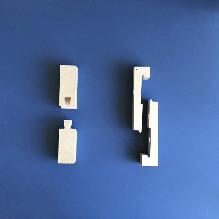
In order to fully understand how joinery was designed and how does it work in terms of geometry interlocking, the break them down to the most origin status, the initial geometry without any further designed detail, and then try to link the design process in between. Two principal was discovered, first, the joint insert direction needs to be defined since the beginning, it has to be vertical or opposite to gravity, second, manipulate with the geometry trying to stop the joinery to be removed from all the other direction than the insert direction. Every joinery was designed with these two principals no matter how complicated they are. Take the most commonly seen joinery “stepped dovetailed splice“ as an example, it is the simplest joinery, the design process can be broken down into three parts, the first is the initial, just a very basic tenon and mortise without any specific angle or obstacle, at this condition the joint can be freely removed from direction of Z+, Y ±, then in the second step a obstacle at the bottom blocked the way to remove from Y-, only Z+ and Y+ remain, eventually the tenon opens up to a trapezoid that blocked the way to remove from Z+, at the end, it can be only insert or remove from direction of Y+. Under this two principal, no matter how complicated the joinery type is, it is very easy to understand how different pieces of geometry work as an interlocking system, then follow on it is easy to modify or design a new joinery according to different needs.
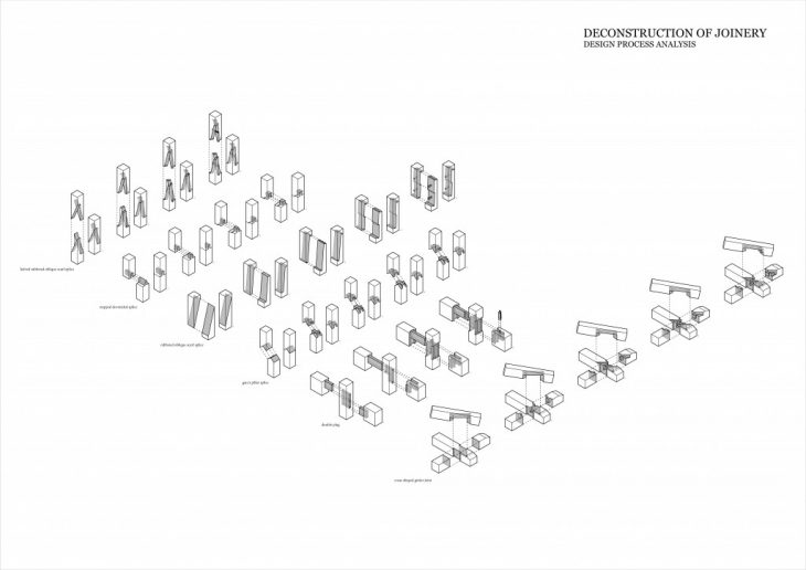
understanding joinery by deconstructing the geometry into design steps
The first experiment is to make joinery by digital fabrication method, make two different type of joinery by a shopbot CNC milling machine. With very simple 3D modeling converted into 2D curves in Rhino and transform into G-code by Rhino CAM, with the help of CNC milling specialist Alejandro Rondon, this experiment succeed without any problem, still there are some issues need to be noted. First, the tool size matters, the diameter of the milling bit determines the size of the fillet of the corner, it is the biggest restraint of 3 axis CNC milling that it is impossible to get a sharp corner like the one did by chisel. Second, it is impossible to mill anything with negative angle or under top surface since in 3 axis milling the mill bit can only move vertically, in this case, many types of complex joinery that has mortise in the middle are not able to be made by milling machine. But there is an alternative to solve this issue, the joinery has to be divided into layers and milled layer by layer and glued, after all, it is the only way to achieve the joinery which has a hole in the middle, but it can not solve the negative issue still. In this research, glue wouldn’t be considered as a cheating, since glued wood is a part of the material revolution, it is a technique to solve the restriction of the tool and it is involved in the experiment after.
With the knowledge of traditional and digital joinery making, the next experiment is releasing joinery from a straight bar structure that follows a line to a curved structure follows a curve, firstly start with a two dimension curve, if succeed, move on three dimension curve.
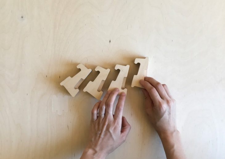
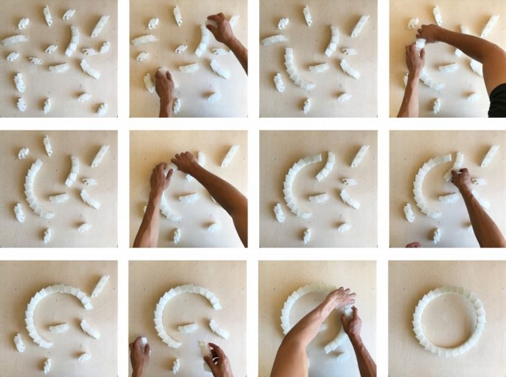
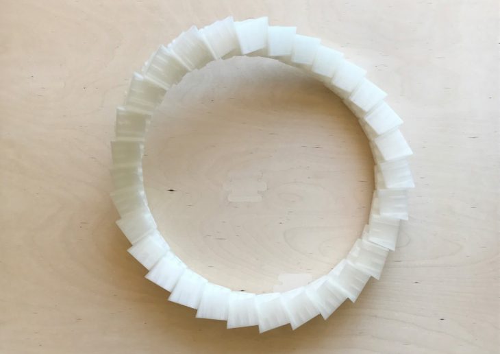
Two dimension curved joinery is actually an easy task. Imagine the curved bar is splited into segments, each segment has tenon on one side and mortise on the other side and there are angles between each tenon and mortise, this is the initial thought about curved joinery, it is not curving joinery itself but giving angles between each joinery. The first experiment went quite successful, it aims to achieve a ring structure with several segments of wood, the only restriction is it has to be made out of plywood sheet so the top and bottom surface need to be flat and parallel. The ring is divided into 30 pieces so there are 12 degrees different in between each piece. Having in mind the two principal of joinery designing, a new type of joinery that fit the ring structure came out easily, with the experience from previous making experiment, it is easy to mill a set of joinery with nice tolerance that easily assembled.
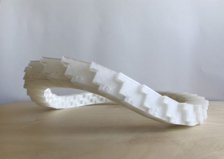
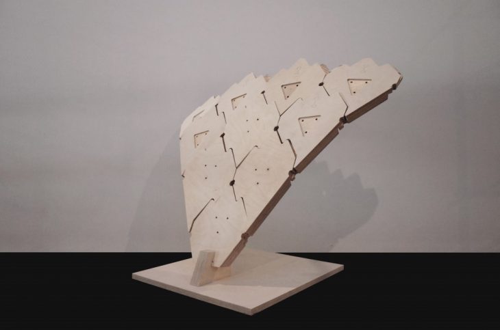
Three-dimensional curve is the next, it shares the same idea with the previous experiment but it is a lot more difficult in terms of execution. There are two main difficulties in this experiment, first, the 3D modeling of three-dimensional curve is much more difficult than 2D curve especially in processing complex geometry, in addition, the top and bottom need to be parallel, it just made the modeling part even challenging. Second, as mentioned before, the experiment works with 3 axis CNC milling machine, so all the negative angle or inner joint need to be eliminated from the design, in order to fit the fabrication condition, some design method are required.
First, one single joint need to be designed, in this experiment the joint type is retrofitted from the 2D curve joint. After the joint type is determined, the joint direction need to be defined, either clockwise or anti-clockwise, then a poly surface box is applied to the curve along the orientation of each node on the curve, this means the pieces should be always perpendicular to the curve, then the mortise is applied on one side of box and tenon goes to the other side of box where fit the mortise of adjacent pieces, this how the angle between each piece were created. Eventually it is certain that in each piece there is one side perpendicular to the top and bottom surface, and one side has the angle that adapts the curve, this ensures two issue, first, the assembling method is clear and there will be no conflict between the insert angle of each piece. Second, the all negative angle is eliminated since on side is perpendicular, all the odd angle happens only on the other side, so there will be no milling difficulties or requires of flipping side milling.
——————- Surface expanded joinery system in shell structure ——————-
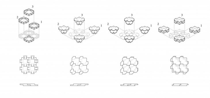
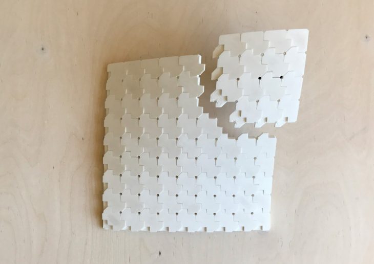
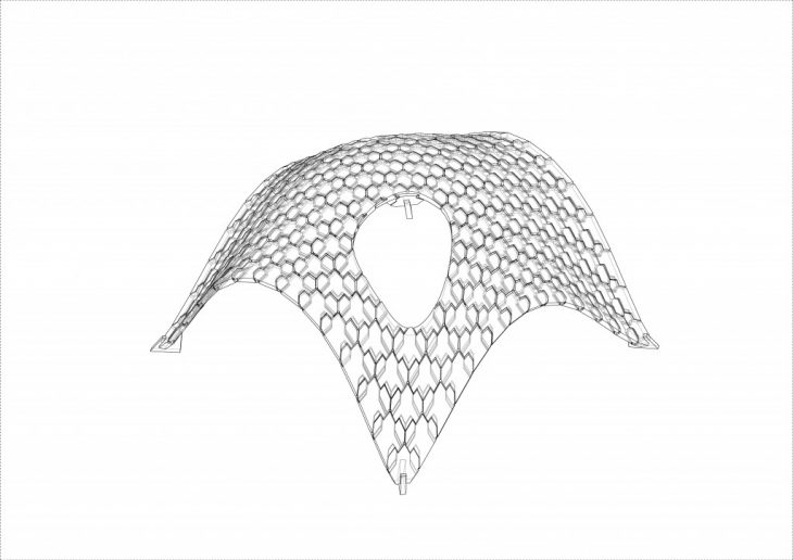
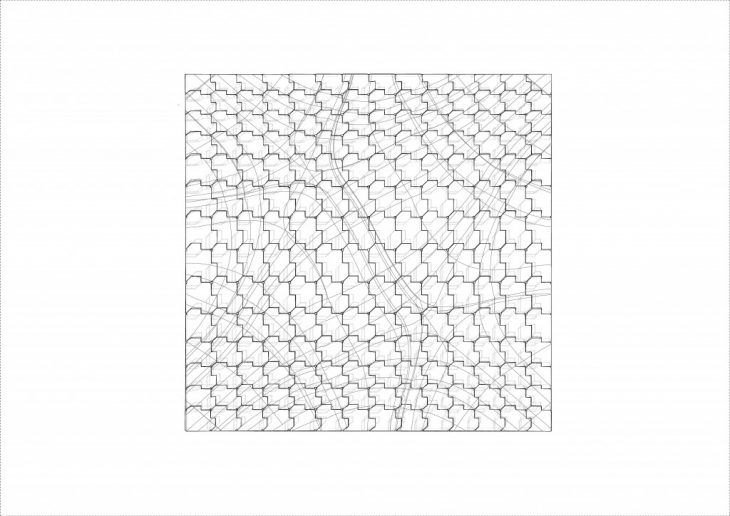
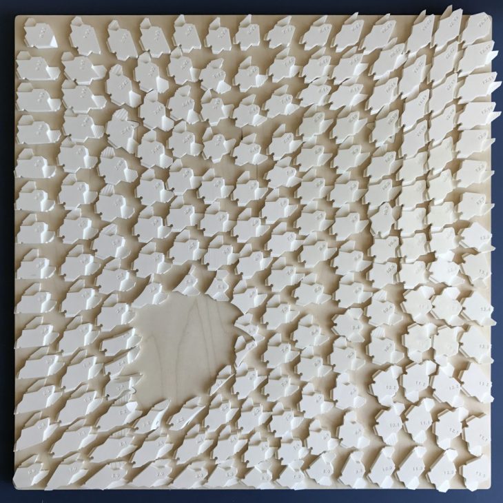
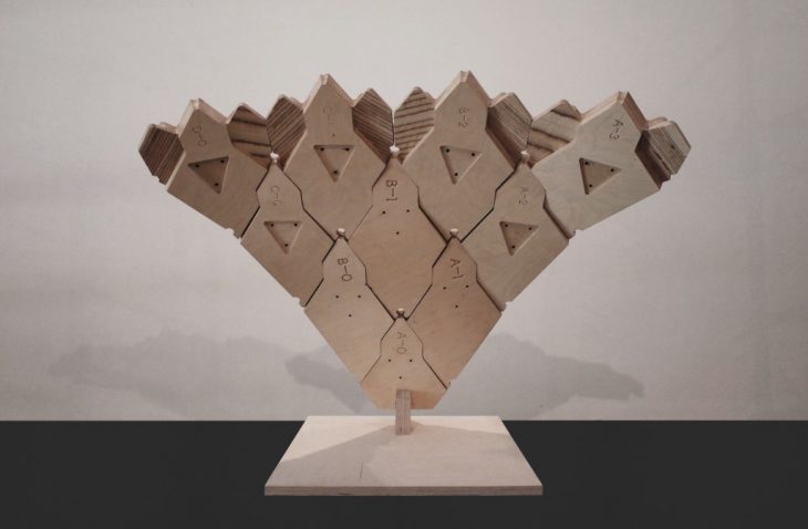
Then the research moved on next step, Panelization of the construction, it makes the surface extension of joinery possible, by dividing a shell surface into pieces of quadrilateral with multiple-axis joint, a complex shell structure can be achieved with the small scale of the wood piece that cut out from a flat wood sheet. To unify the joint orientation, a method is introduced in the system, when generating the basic pieces of joint, the front two side surfaces must be perpendicular to the surface normal and the back two side surface adapts to the adjacents, only in this case the pieces can be joint with neighbor pieces without confliction of joining axis. The revolution of design tools, material, machinery transform the notion of traditional joinery into a customized, scaffolding less, movable and easy assemble shell structure system.
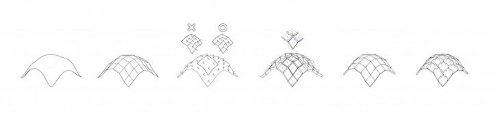
basic joinery design logic
basic joinery development
3D printing mockup
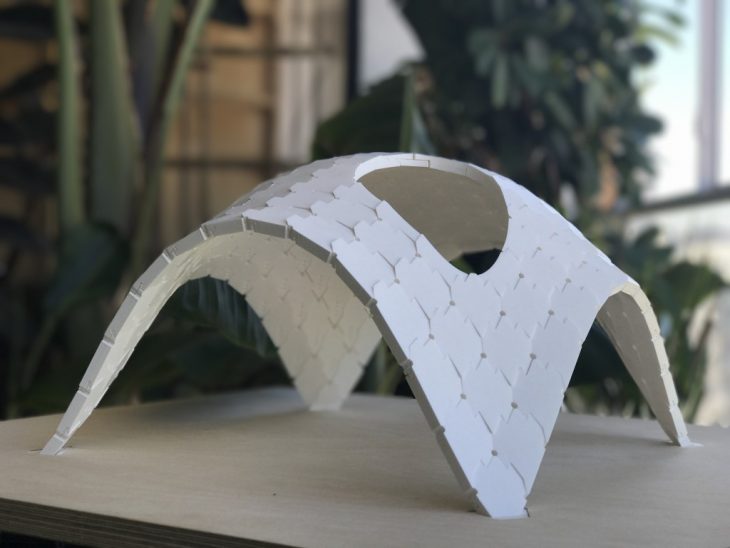
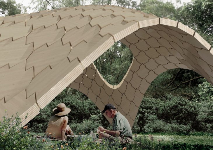
The success of the surfaced expanded joinery experiment leads the research to next step, applying the system on a shell structure. The brick vault designed by Norman Forster and Philippe Block was chosen to be the challenge model, the challenge is if the system can work in the same form of the pavilion without the help of other component and assemble without scaffolding.
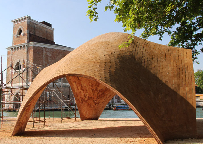
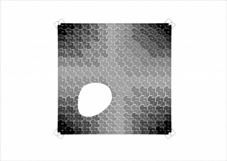
In order to further strengthen the advantage of wooden joinery structure: toughness against seismic, principal stress line analysis is introduced in this research. The structural analysis shows the force load on the shell structure, which gives an opportunity to optimize the tolerance of joint in order to improve the ability to absorb force when facing earthquake.
according to the load of the force, the tolerance between each piece is adjusted to give space for avoiding breakage from distortion caused by the earthquake.
plan
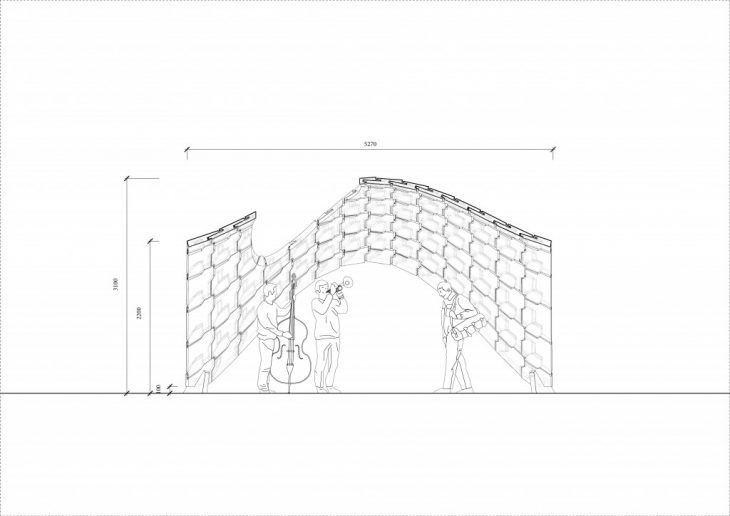
section
——————- assemble process ——————-
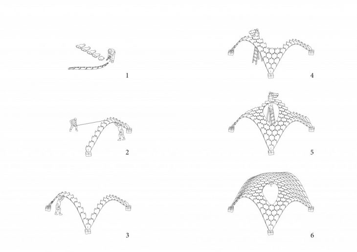
196 pieces assemble process
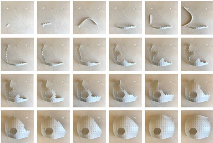
——————- fabrication process ——————-
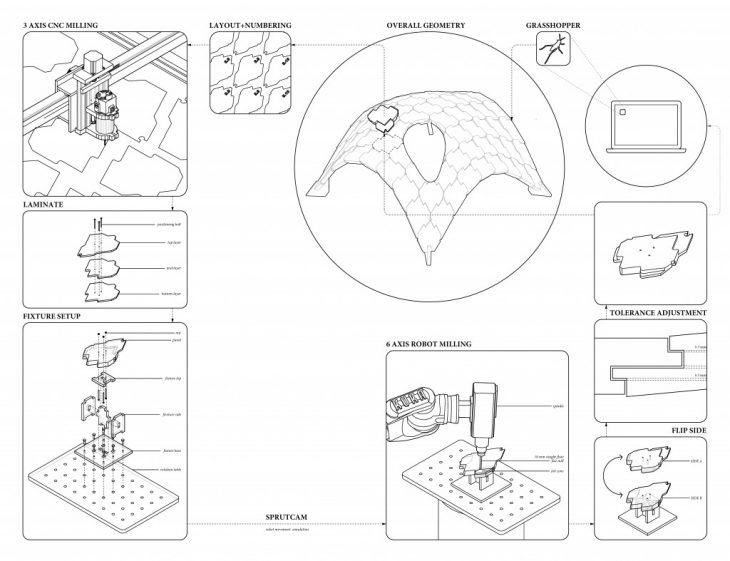
</p>
1/2 prototype
To shortly conclude, this project investigates the changes of joinery construction brought by the material and fabrication revolution, it transformed traditional joinery technique into construction method that has potential to adapt current architecture environment, this research should not be considered as a wooden construction method, it is a joining method that doesn’t require fastener or scaffolding, a system that material joint together only by geometry, it is a system that can be achieved by all the other potential material
Redefining Joinery is a Project of IaaC, Institute for Advanced Architecture of Catalonia developed at Master in Advanced Architecture in 2016/2017
Student : Hsin Li
Supervisor : Jordi Pagès i Ramon and Lluís Viu Rebés